1
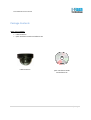
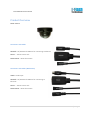
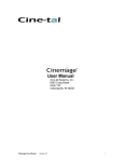
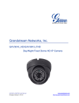
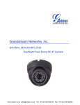
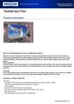
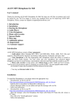
Pulse P2DS Series User Manual
Pulse IP Camera User Manual
Model Number: P2DS Series
Revision: 3.0.1.2
1|Page
Pulse P2DS Series User Manual
Safety Instruction
These instructions are intended to assist users with the operation of the P2DS and also to instruct on
how to avoid dangerous situations or damage to the device.
Warnings: Serious injury or death may be caused if any of the warnings below are neglected.
Cautions: Injury or damage to the equipment may occur if any of the following caution
messages are neglected.
Warnings Follow these safeguards
to prevent serious injury or death.
Cautions Follow these precautions
to prevent potential injury or material
damage.
Warnings:
Input voltage should meet both the SELV (Safety Extra Low Voltage) and
the Limited Power Source with DC 12V according to the IEC60950-1
standard. Please refer to the technical specifications for more details.
Do not use a third-party power adapter or power cord
When the device is installed on the wall or ceiling, make sure that it is
firmly attached.
2|Page
Pulse P2DS Series User Manual
Notice:
• Make sure that the power supply voltage is correct before using the camera.
• Do not drop the device or expose it to physical shock.
• Do not expose the device to temperatures outside the range of -10 °C to +50°C
when the device is in operation.
• Do not expose the device to damp/wet conditions or high electromagnetism
radiation.
• To avoid heat accumulation, make sure that your operating environment has
proper ventilation.
• Do not attempt to open, disassemble, or modify the device
• A few parts (e.g. electrolytic capacitor) of the equipment shall be replaced
regularly according to their average life time. The average life time varies from
the differences between operating environments and usage history. Regular
maintenance checks are recommended for all users. Please contact your dealer
for more details.
3|Page
Pulse P2DS Series User Manual
Contents
Welcome …………………………………………………………………………………………………………………
Package Contents …………………………………………………………………………………………………
Product Overview …………………………………………………………………………………………………
Configuring the P2DS via Web Browser ………………………………………………………
Access P2DS Web Configuration Menu ………………………………………………
Connect The Camera to DHCP server ……………………………………………………………
Connect to the Camera using Static IP ……………………………………………………………
Home Web Page ……………………………………………………………………………………………
System Page …………………………………………………………………………………………………
Video & Audio Page ……………………………………………………………………………………..
Networking Page……………………………………………………………………………………………
DDNS Page…………………………………………………………………………………………………….
SIP Page………………………………………………………………………………………………………….
Status Page …………………………………………………………………………………………………..
User Management Page …………………………………………………………………………………..
Maintenance Page …………………………………………………………………………………………
SMTP Page …………………………………………………………………………………………………….
FTP Page ……………………………………………………………………………………………………….
Alarm HTTP Server Setting…………………………………………………………………………….
Motion Detection Page …………………………………………………………………………………
System Log ……………………………………………………………………………………………………
5
6
7
10
10
10
11
12
14
15
16
19
21
23
25
26
27
28
29
30
32
4|Page
Pulse P2DS Series User Manual
Welcome
The P2DS is a next generation mini IP dome camera for remote monitoring and
surveillance over your LAN or internet.
The P2DS combines best in class IP video technology and SIP protocols for a robust IP
surveillance solution. The product features H.264 video streams with up to 30 frames per
second in full D1, delivering rich image clarity at rapid transmission rates. Integrated SIP can
pass alarms to the PSTN, mobile phones, SIP IP phones, SIP videophones and enables
2-way VoIP communication.
The P2DS ensures ease of use, integration and deployment with a multilingual graphical
user interface. The P2DS can be quickly installed and connected to your network and
accessed from anywhere over the internet. i-Flash Technology flexible video management
software enables users to monitor multiple environments in one easy to use application. The
intuitive web interface lets users easily access, manage, view and record live video streams
from the device.
The P2DS is a powerful solution for small to medium sized offices, homes and storage
facilities looking to safeguard their valuables.
5|Page
Pulse P2DS Series User Manual
Package Contents
Items in the package:
•
•
P2DS IP Camera
Quick Installation Guide and Software CD
P2DS IP Camera
Quick Installation Guide
and Software CD
6|Page
Pulse P2DS Series User Manual
Product Overview
P2DS Camera
Connectors and Cables
Network: 10/100 Switch LAN Port for connecting to Ethernet
Power – 12V DC Power Jack
Reset Button – Reset the Camera
Connectors and Cables (With Audio)
Audio: Audio Input
Network: 10/100 Switch LAN Port for connecting to
Ethernet
Power – 12V DC Power Jack
Reset Button – Reset the Camera
7|Page
Pulse P2DS Series User Manual
P2DS Key Features
Video Compression
H.264 HP、JPEG, Motion JPEG
Image Sensor
1/3.2”, 2-Megapixel CMOS, 1,600Hx1,200V
Lens
1/3", M12 MEGA, f=3.6 mm, F=1.8 (Selectable)
Day/Night
IR Light and IR-CUT control (Optional)
Min. illumination
0.5Lux
Min. illumination Response
1.0V/lux-sec (550nm)
Max Video Resolution
1600x1200
Max Frame Rate
6 fps 1600x 1200, 25fps at 1280x720, 30fps at
800x460, 640x360, 480x270, 320x180 and 240x135
Pixel Dynamic Range
71dB, with ( SNRMAX = 42.3dB)
Video Output
NTSC or PAL Complex video signal
Frame Rate
10-30fps
Video Compression Type
Video Stream / Complex Video Stream
Compressed Video Output rate
16Kbps - 2Mbps
Audio Input
MIC IN (optional)
Audio Output
Linear output (LINEOUT,600Ω, Optional)
Audio Compression Standard
G.711
Audio Compression Rate
16-96kbps,support8-16KHz
Network Connection
RJ45 10M/100M Ethernet
Power
12VDC or PoE with Splitter
Operation Temperature
-10°C – 45°C
Operation Humidity
10–90%(non-condensing)
Dimension
107 mm diameter
Weight
~ 450g
8|Page
Pulse P2DS Series User Manual
Installation Guide
Minimum Recommended System Requirement
• Windows 2000 Server Professional, Windows XP, Windows Vista, Windows 7
• CPU: Intel Pentium 4 or higher, 2 GHz.
• RAM: 1 GB (4 GB recommended for larger systems).
• Support for DirectX 8.0 and above.
Connect your P2DS
Using the Power adapter as power supply
• Connect an RJ-45 cable to the NETWORK port of the P2DS.
• Connect the other end of the RJ-45 cable to your network or PC.
• Connect the power supply to the DC 12V power jack on the back of the P2DS.
• Connect the other end of the power supply with 12VDC 1A minimum to a wall outlet (not included)
Using PoE as power supply with PoE Splitter (not included in Package):
• Connect an RJ-45 to the NETWORK port of P2DS.
• Connect the other end of the RJ-45 cable to a PoE switch.
NOTE: If you are going to connect the device to a hub/switch/router, please use a straight-through cable.
A cross over cable should be used if you are going to connect the device directly to a PC.
9|Page
Pulse P2DS Series User Manual
Configuring the P2DS via Web Browser
The P2DS’s embedded Web server responds to HTTP/HTTPS GET/POST requests.
Embedded HTML pages allow you to configure your IP camera through Microsoft Internet Explorer.
Access P2DS Web Configuration Menu
Connect the Camera to DHCP server.
1. Run the Search tool provided in Software CD
2. Click on button in order to begin device detection
3. The detected devices will appear in the Output field
4. Start Internet Explorer on your computer
5. Enter device IP in the address bar of the browser or double click the camera in Search tool
6. Enter the administrator user name and password to access the Web Configuration Interface
7. The default user name and password are both set to admin.
8. IE will indicate that “This website wants to install the following add-on:
9. Install this add-on by following the instructions in IE.
10. You will see the home page.
10 | P a g e
Pulse P2DS Series User Manual
Connect to the Camera using Static IP
If the camera does not get response from DHCP server after 3 minutes, it can be accessed by the default
IP 192.168.1.168.
1. Connect your PC to the same network as the P2DS.
2. Configure the IP address of your PC to: 192.168.1.XXX (1<XXX<255) and configure the subnet
mask to 255.255.255.0.
3. Make sure that the device is turned on and connected to the network.
4. Start Internet Explorer on your computer.
5. Enter 192.168.1.168 in the address bar of the browser.
6. Enter the administrator user name and password to access the Web Configuration Interface
7. The default user name and password are both set to admin.
8. IE will indicate the add-on required that Install this add-on by following the instructions in IE.
9. You will see the home page.
11 | P a g e
Pulse P2DS Series User Manual
P2DS Home Web Page
1
Motion Detection
2
Control Console
3
4
5
6
ZOOM
Focus
PTZ Speed
Default
7
BRIGHTNESS
If the motion detection alarm is triggered, the
indicator will flash red. Click on the indicator to turn
off the alarm.
PTZ Console controller. PTZ device needs to be
connected. (not supported in P2DS)
Zoom control (not supported in P2DS )
Adjust focus of image (not supported in P2DS)
Adjust PTZ Speed (not supported in P2DS)
Click this option to reset the video brightness,
contrast, and saturation to their factory default
configuration.
Adjusts the image brightness.
12 | P a g e
Pulse P2DS Series User Manual
8
9
CONTRAST
View Size
10
11
12
13
Configuration
Language
Play / Stop
Capture
14
Record
15
16
17
18
Sound Off/On
Talk
Playback
Config
Adjusts the image contrast
Resize the image to fit into the window panel in the
home scream
Camera Configuration Setting
Select language – English or Chinese
Plays/Stops the video.
Captures the image displayed and saves it to
C:\GS_Capture (default directory).
Records the video and saves it to C:\GS_Record
(default directory).
Toggles the sound On or Off
Establishes two-way audio
Replays the saved video
Configures the Save Location for captured images and
recorded videos.
13 | P a g e
Pulse P2DS Series User Manual
P2DS System Page
The page allows you to configure the system setting on P2DS
Current System Time - displays the current date and time (24h clock).
Set the System Time
•
•
•
•
Update via NTP Server - the camera will obtain the time from an NTP server Specify the NTP
server's IP address or host name. And you can select your time zone from the drop-down list or
define your own time zone setting.
o NOTE: If using a host name for the NTP server, a DNS server must be configured under
Basic Settings -> Networking.
Synchronize with Local Computer - sets the time from the clock on your computer.
Set the Time Manually - this option allows you to manually set the time and date.
OSD Date Format - set the format of date on OSD
14 | P a g e
Pulse P2DS Series User Manual
15 | P a g e
Pulse P2DS Series User Manual
Device Name Setting –This field lets you configure the name of the P2DS, which helps “Search” and
“Surveillance” Software to identify the device in the same subnet.
Video & Audio Page
On Screen Display (OSD) Settings OSD Time/ Text – The time stamp and channel name displayed on the
screen.
16 | P a g e
Pulse P2DS Series User Manual
Video Settings
Preferred Video Codec
Resolution
Bit Rate
Maximum Frame Rate
Bit Rate Control
Image Quality
I-frame Interval
– The P2DS supports the H.264 video codec.
– The higher the resolution is, the better the video quality is, and higher
bandwidth is required.
– The number of bits that are conveyed or processed per unit of time.
– The video frame rate is adjustable based on network conditions.
Increasing the frame rate will increase the amount of data significantly
therefore consuming more bandwidth. Video will be impaired due to packet
loss when there is insufficient bandwidth.
– Variable Bit rate (VBR) and Constant Bit Rate (CBR).
Variable Bit Rate - If VBR is selected, the codec varies the amount of output
data per time segment. VBR produces a better quality-to-space ratio. The
bits available are used to enable more flexibly and encode sound or video
data more accurately, with fewer bits used in less demanding passages and
more bits used in difficult-to-encode passages.
Constant Bit Rate - If CBR is selected, the codec’s output data is constant
regardless of the input data. The output bit rate is defined in “Bit rate”. CBR
is useful for streaming multimedia content on limited capacity channels. It is
easier to calculate required bandwidth as well as the required storage space
using CBR.
If ‘Bit Rate Control’ is set to “VBR”, “Image quality” needs to be configured.
The better the video quality is, the higher the bit rate will be.
– While streaming video over a network, compression technologies are
used to show the incremental difference between each frame. I-frames
are used to help keep the video looking normal. When intervals are
17 | P a g e
Pulse P2DS Series User Manual
shorter, the video quality is higher but uses more bandwidth.
NOTE: The users might need to configure the Primary Stream and Secondary Stream properly.
Sometimes, the user might like to watch the live video stream from the web GUI in low resolution mode
while recording a copy via “Surveillance System” software in high resolution due to the limitation of
internet bandwidth. In this case, for example, primary stream can be configured to have better
resolution, and then the users can use primary stream to record while watching secondary video
streams.
Audio Settings
Preferred Audio Codec – The P2DS supports up to 3 different Vocoder types, a-law
(PCMA), u-law (PCMU) and G.726. The audio can also be turned off by switching the setting
to “Disabled”
Power Frequency - this setting should match the power frequency used in the country to avoid flickering
in the image
18 | P a g e
Pulse P2DS Series User Manual
Networking Page – Assign an IP to P2DS
P2DS supports IP version 4. The IP address can set automatically via DHCP, or a static IP address can be
set manually. To make P2DS work properly, the user needs to set the DNS configuration properly. For
security purposes, the user can also assign the P2DS an HTTP Port other than 80
IP Address Configuration
The P2DS operates in two modes:
Dynamically Assigned via DHCP – all the field values for the Static IP mode are not used. The P2DS
acquires its IP address from the first DHCP server it discovers on its LAN.
Statically Configured as – configures all of the following fields: IP address, Subnet Mask, Default
Gateway IP address, DNS Server 1 (primary), DNS Server 2 (secondary). These fields are set to zero by
default. Static IP addresses are recommended for the P2DS
DNS Configuration
There are two methods of DNS configuration on the P2DS:
1. The P2DS can obtain the DNS server automatically
2. Users can configure their own preferred DNS server
19 | P a g e
Pulse P2DS Series User Manual
HTTP Port
The P2DS supports user configured http ports. If the HTTP port is changed, the port number is needed to
access the web GUI, for instance: http://192.168.1.168:8080.
NOTE: If the HTTP Port is 80, when you add this device to Surveillance Software, the RTSP port is 554. If
the HTTP Port is changed, when you add this device to Surveillance Software, please make sure the RTSP
port number equals HTTP Port plus 2000.
DDNS Page
Dynamic DNS provides devices that have a variable, often changing IP address with a well known
hostname resolvable by network applications through standard DNS queries.
20 | P a g e
Pulse P2DS Series User Manual
Set up DDNS
1. Apply for a domain name from your service provider.
2. Login to the web configuration page, click Basic Settings > DDNS.
3. Enter the required information
•
•
•
•
•
•
DDNS Active – If you want to use DDNS, please set this field to “Enabled” .
DDNS ISP Type – Select your DDNS ISP Type.
Self-Define DDNS Address – Self-define the DDNS server instead of using DDNS ISP Type.
Site Name – The DDNS name for your device.
DDNS Account/ DDNS Password – The account and password from the DDNS Provider
STUN Server – If the device is behind a router, a STUN server is needed to help penetrate
the NAT.
4. Click Save to save the changes. You might need to reboot the device to apply all the changes.
21 | P a g e
Pulse P2DS Series User Manual
SIP Page
The P2DS has the ability to receive phone calls and make phone calls when an alarm event is triggered
through motion detection or alarm input. Register the P2DS to a SIP server to enable the product to
make and receive phone calls. To make outgoing phone calls out, the user needs to configure the Phone
List properly.
22 | P a g e
Pulse P2DS Series User Manual
Register P2DS to a SIP Server
1. From the P2DS home page, click Basic Settings > SIP.
2. Go to SIP Settings Tab.
3. General Phone Settings.
Registered – The field shows the registration status of the account with the SIP server.
Unregister On Reboot – If it’s checked, the SIP user’s registration information will be cleared
from the server when the phone reboots.
4. Enter the required information.
Account Name
SIP Server
Outbound Proxy
SIP User ID
Authenticate ID
Authenticate Password
STUN Server
Stream
Preferred Vocoder
Registration Expiration
Local SIP Port
– The field configures the SIP account name.
– The SIP Server’s IP address or Domain name provided by your service
provider.
– The IP address or Domain name of the Outbound Proxy, Media Gateway,
or Session Border Controller. Used for firewall or NAT penetration in
different network environments. If the system detects a symmetric NAT,
STUN will not work. ONLY outbound proxies can provide a solution for a
symmetric NAT.
– User account information provided by your service provider (ITSP); this is
either an actual phone number or is formatted like one.
– The SIP service subscriber’s Authenticate ID used for authentication. It
can be identical to or different from the SIP User ID.
– The SIP service subscriber’s account password for the GXV to register to
the SIP server of the ITSP.
– If the device is behind a router, a STUN server is needed to help
penetrate the NAT.
– To choose between Primary and Secondary stream.
– To choose different Vocoder type.
– This parameter allows users to specify the time frequency (in minutes) in
which the GXV refreshes its registration with the specified registrar. The
default interval is 60 minutes.
– This parameter defines the local SIP port used to listen and transmit. The
default value is 5060. Local RTP Port – This parameter defines the local
RTP-RTCP port pair that is used to listen and transmit. The default value is
5004.
5. Click Save to save all the changes. You need to restart the device to apply all changes.
23 | P a g e
Pulse P2DS Series User Manual
Configure Phone List Page
To make sure the P2DS can make phone calls to the number you preferred when alarm is triggered. You
need to add number to the phone list.
Steps to add phone number:
1. From the P2DS home page, click Basic Settings > SIP.
2. Go to Phone List Tab.
3. Enter the Phone number and name, click Add a Number to save all the changes.
4. Numbers added to the system will be listed in this page.
Status Page
System Statistics
System Statistics lists hardware and software information, for example, the part number, the software
version, about the P2DS
Hardware Version – This field contains the product’s hardware information.
Part Number – This field contains the product part number information.
Bootloader Version – Bootloader code version number.
Core Version – Core code version number.
Base Version – Base code version number.
Firmware Version – Firmware code version number.
24 | P a g e
Pulse P2DS Series User Manual
System Up Time Since – This field shows the system up time since the last reboot.
Network Status
MAC Address – The device ID, in HEXADECIMAL format.
LAN IP Address – This field shows the LAN IP address of
the P2DS.
LAN Subnet Mask – This field shows the LAN subnet
mask of the P2DS.
LAN Default Gateway – This field shows the LAN default
gateway of the P2DS.
DDNS Status – This field shows the status of DDNS.
Camera Type
This section shows the sensor information of P2DS.
25 | P a g e
Pulse P2DS Series User Manual
P2DS User Management Page
All current users will be list in the User List section of this page. You can also add and remove users here.
Existing User Name –The field lists all of the current users. You can insert or remove users from the list
by click on the Add or Update or Delete button.
User Name / Password – The user name and password required to login.
Privilege – The privilege for the user to access to configuration page.
Allow Anonymous Login – If ‘Allow Anonymous Login’ is set to Yes, no user name and password are
required to login to the P2DS web configuration pages. If you login anonymously, you will not be able to
change any settings.
26 | P a g e
Pulse P2DS Series User Manual
P2DS Maintenance Page
Server Maintenance
Restart – Click this button to restart the P2DS.
Restore – Click this button to perform a partial factory reset (The IP
address will not be cleared).
Restore the Device
Click “Restore” to reset the camera to default factory setting, except IP
Address.
Firmware Upgrade and Provisioning Items
Upgrade via – This field lets you choose the firmware upgrade method. The P2DS supports
HTTP, HTTPS and TFTP.
Firmware Server Path – The IP
address or domain name of the
firmware server (the location of the
firmware files) .
Automatic Upgrade Interval – Enter
the frequency (in minutes) in which
the HTTP/HTTPS/TFTP server will be
checked for new firmware upgrades
or configuration changes.
Automatic Upgrade – The default
setting is “No.” Choose “Yes” to
enable automatic. HTTP/HTTPS/TFTP
upgrade and provisioning. When set to “No”, the IP Camera will only perform a HTTP/HTTPS/TFTP
upgrade and perform a configuration check once during the boot process.
27 | P a g e
Pulse P2DS Series User Manual
Performing a firmware upgrade:
1. Download the firmware package from www.i-flashtech.com
2. Unzip the firmware package and copy the files to the firmware upgrade server directory. Upgrades
are supported via TFTP, HTTP and HTTPS.
3. Log in to the Maintenance page of the P2DS. Select the server type from the dropdown list under the
“Upgrade Via” field. Enter your server’s root directory in the “Firmware Server Path” field.
4. Reboot the P2DS to begin the firmware upgrade process.
SMTP Page
The SMTP server is used to send out emails when alarm event or motion detection is triggered. The
SMTP settings must be configured to make sure the alarm email is sent out properly.
28 | P a g e
Pulse P2DS Series User Manual
SMTP Server Settings
Enable SMTP – Checked to enable SMTP
SMTP Server – The IP or hostname of the SMTP server, for example,
smtp.gmail.com.
SMTP Server Port – The port of the SMTP server. The P2DS supports
port 25 and SSL port 465, which is for SMTP with an encrypted
connection.
From E-Mail Address – The email address that sends out the alarm
email(s).
To E-Mail Address – The email addresses that the alarm email(s) will be
sent to. You can have up to 3 emails configured.
User Name/ Password – The user name and password required to log
in to your SMTP server, for example, [email protected]/123.
SSL – Checked if the SMTP server requires a secure connection.
Test Email Account Settings – Click the Test button to send a test email from the From E-Mail to the To
E-Mail to make sure that SMTP is configured properly. If the receiver can get the test email, then the
SMTP settings are ready to go.
FTP Page
The FTP server is used to store video files if you configure the P2DS to record video and upload it to the
FTP server when an alarm event or motion detection is triggered.
FTP Settings
Enable FTP – The default setting is “No,” if you want the P2DS to upload the
recorded video to the FTP server when an alarm is triggered, set this field to
“Yes.”
FTP Server – The IP address or hostname of the SMTP server, ie.
ftp.myserver.com.
FTP Server Port – The port that your FTP server is using.
User Name / Password – The user name and password required to log into your FTP server
29 | P a g e
Pulse P2DS Series User Manual
Path – The directory in the FTP server where recorded video will be uploaded.
Test FTP Account Settings – Click the Test button to upload a sample file to make sure that FTP is
properly configured.
PTZ Settings
This setting is not supported in P2DS
Alarm HTTP Server Settings
Server Name: input the Server Name
URL: input the Server IP Address
User Name & Password: input User Name & Password
30 | P a g e
Pulse P2DS Series User Manual
Motion Detection Page
The P2DS supports Motion Detection. To utilize this feature, please follow the below steps:
1. Setup the motion detection monitored area.
2. Configure the motion detection time schedule.
3. Configure alarm action properly.
Setup Motion Detection Monitored Area
Enable Motion Detection – If this option is selected, motion detection will be enabled. If
something/somebody moves in the motion detection region, an alarm will be triggered.
Show Motion Detection Regions – If this option is selected, the motion detection regions will be
displayed on the screen with a white border.
To Edit a Monitored Area
1. In the Select a Region dropdown list, select the region ID.
2. Click Edit.
3. Click on the video, drag and draw you preferred area.
4. Set the Sensitivity. Click the Save button to save the sensitivity.
NOTE: The Sensitivity value varies from 0 to 100. The larger the value is, the higher the sensitivity.
5. Click Save to save the settings.
To Remove a Monitored Area
1. In the Select a Region dropdown list, select the region you would like to remove.
2. Click Remove.
3. Click Save to save the changes.
31 | P a g e
Pulse P2DS Series User Manual
Configure Motion Detection Time Schedule & Alarm Actions
This section allows you to configure the time during which the P2DS will monitor the motion detection.
The P2DS not only can monitor your settings but also can take actions when the alarm is triggered.
32 | P a g e
Pulse P2DS Series User Manual
P2DS System Log
This page is used to set up the system log server path and system log level. Once they are correctly
configured, the device will send out system log messages to the system log server, which will help
perform troubleshooting.
Syslog Server – The IP address or URL of System log server.
Syslog Level – Select the device to report the log level. Default is None. The level is one of Debug, Info,
Warning or Error.
33 | P a g e