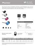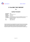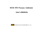
1
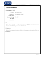
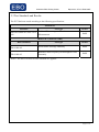
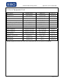
Shenzhen EBO Testing Center
Report No. CE11-LIE090126E
EMC TEST REPORT
Report No.: CE11-LIE090126E
Product: LED SPOT LIGHT
Model No.: CE-15W5000K-AR3002, CE-15W3000K-AR3001
Applicant: SHEN ZHEN C.E OPTOELECTRONIC.CO., LTD
Address: A BLOCK, SHENG YANG TECHNOLOGY PARK, DA FU
INDUSTRIAL AREA, GUAN LAN TOWN, BAO AN
DISTRICT, SHEN ZHEN, CHINA
Issued by: Shenzhen EBO Testing Center
Lab Location: Yihua Building, Shennan Road, Futian District, Shenzhen,
518040, P. R. China
Tel: 86 755 29451282
Fax:86 755 22639141
This test report consists of 16 pages in total. It may be duplicated completely for legal use with
the approval of the applicant. It should not be reproduced except in full, without the written
approval of our laboratory. The client should not use it to claim product endorsement by EBO.
The test results in the report only apply to the tested sample. The test report shall be invalid
without all the signatures of testing engineers, reviewer and approver. Any objections must be
raised to EBO within 15 days since the date when the report is received. It will not be taken into
consideration beyond this limit.
Page 1 of 16
Shenzhen EBO Testing Center
Report No. CE11-LIE090126E
Table of Contents
1
2
Test Report Certification ...............................................................................................................3
General Information ......................................................................................................................4
2.1 Description of EUT ...............................................................................................................4
2.2 Objective ...............................................................................................................................4
2.3 Test Standards and Results ....................................................................................................5
2.4 List of Equipments Used.......................................................................................................6
3 Emission Test ................................................................................................................................7
3.1 EUT Setup and Operating Conditions...................................................................................7
3.2 Radiated Electromagnetic Disturbance Measurement ..........................................................7
3.2.1 Limits of Radiated Electromagnetic Disturbance ......................................................7
3.2.2 Test Procedure ............................................................................................................7
3.2.3 Test Setup ...................................................................................................................8
3.2.4 Test Results ................................................................................................................8
4 Immunity Test ............................................................................................................................. 11
4.1 EUT Setup and Operating Conditions................................................................................. 11
4.2 Performance Criteria ........................................................................................................... 11
4.3 Electrostatic Discharge Immunity Test ............................................................................... 11
4.3.1 Test Specification ..................................................................................................... 11
4.3.2 Test Procedure ..........................................................................................................12
4.3.3 Test Setup .................................................................................................................13
4.3.4 Test Result ................................................................................................................13
4.4 Radiated, Radio Frequency Electromagnetic Field Immunity Test ....................................14
4.4.1 Test Specification .....................................................................................................14
4.4.2 Test Procedure ..........................................................................................................14
.4.3 Test Setup ...................................................................................................................15
4.4.4 Test Result ................................................................................................................15
Appendix I:Photographs of the EUT..............................................................................................16
Page 2 of 16
Shenzhen EBO Testing Center
1
Report No. CE11-LIE090126E
Test Report Certification
Product: LED SPOT LIGHT
Model No.: CE-15W5000K-AR3002, CE-15W3000K-AR3001
Applicant: SHEN ZHEN C.E OPTOELECTRONIC.CO., LTD
Applicant Address: A BLOCK, SHENG YANG TECHNOLOGY PARK, DA FU
INDUSTRIAL AREA, GUAN LAN TOWN, BAO AN
DISTRICT, SHEN ZHEN, CHINA
Manufacturer: SHEN ZHEN C.E OPTOELECTRONIC.CO., LTD
Manufacturer Address: A BLOCK, SHENG YANG TECHNOLOGY PARK, DA FU
INDUSTRIAL AREA, GUAN LAN TOWN, BAO AN
DISTRICT, SHEN ZHEN, CHINA
Test Standards: EN 55015:2006+A1:2007+A2:2009
EN 61547:2009
Test Result: PASS
We, Shenzhen EBO Testing Center, hereby certify that the submitted samples of the
above item, as detailed in chapter 2.1 of this report, has been tested in our facility.
The test record, data evaluation and test configuration represented herein are true and
accurate accounts of measurements of the sample’s EMC characteristics under the
conditions herein specified.
Tested by:
,
Date:
September 22, 2011
Smart Li
,
Approved by:
Date:
September 22, 2011
Kevin Yu
Page 3 of 16
Shenzhen EBO Testing Center
2
Report No. CE11-LIE090126E
General Information
2.1 Description of EUT
Product: LED SPOT LIGHT
Model No.: CE-15W5000K-AR3002
Brand Name: /
Electrical Rating: 12V, 15W
I/O Ports: /
Accessories: /
NOTE:
1. Please refer to Appendix I for the photographs of the EUT. For more detailed features
description about the EUT, please refer to User’s Manual.
2.2 Objective
Perform ElectroMagnetic Interference (EMI) and ElectroMagnetic Susceptibility (EMS) tests
for CE Marking.
Page 4 of 16
Shenzhen EBO Testing Center
Report No. CE11-LIE090126E
2.3 Test Standards and Results
The EUT has been tested according to the following specifications:
EMISSION
Standard
EN55015:2006+A1:2007+A2:2
009
Test Type
Radiated Electromagnetic Disturbance
Result
PASS
Measurement
IMMUNITY (EN61547:2009)
Basic Standard
Test Type
Result
EN 61000-4-2
Electrostatic discharge immunity
PASS
EN 61000-4-3
Radiated, radio frequency electromagnetic field
immunity
PASS
NOTE: The latest versions of basic standards are applied.
Page 5 of 16
Shenzhen EBO Testing Center
Report No. CE11-LIE090126E
2.4 List of Equipments Used
Description
Manufacturer
Model No.
Serial No.
Test Receiver
Schwarzbeck
FCKL1528
A0304230
LISN
Schwarzbeck
NSLK8127
A0304233
Loop Antenna
Schwarzbeck
HXYZ8170
A0304232
Amplifier Research
AR AT1080
A0304249
Power Frequency Test System
HAEFELY
PHF 555
A0103105
ESD Test System
HAEFELY
FESD16000
A0103108
Signal Generator
ROHDE&SCHWARZ
SML02
A0304261
Power Amplifier
Amplifier Research
AR 150W1000
A0304247
Power Amplifier
Amplifier Research
AR 75A250M
A0304255
Field Monitor
Amplifier Research
AR FM5004
305128
Magnetic Field Tester
HAEFELY
MAG 100.1
A0103109
Shield Room
Nanbo Tech
Site 3
A9901141
Shield Room
Nanbo Tech
Site 1
A0304210
Antenna
NOTE: Equipments listed above have been calibrated and are in the period of validation.
Page 6 of 16
Shenzhen EBO Testing Center
3
Report No. CE11-LIE090126E
Emission Test
3.1 EUT Setup and Operating Conditions
The EUT was power by DC 12V Mains.
3.2 Radiated Electromagnetic Disturbance Measurement
3.2.1 Limits of Radiated Electromagnetic Disturbance
Frequency range (MHz)
QP Limits(dBμΑ),
for loop antenna with a diameter of 2m
0.009 to 0.07
88
0.07 to 0.15
88 to 58
0.15 to 2.2
58 to 26
2.2 to 3.0
58
3.0 to 30
22
Notes:
(1) The lower limit shall apply at the transition frequency.
(2) The limit decreases linearly with the logarithm of the frequency in the range 70 kHz to 150kHz.
(3) The limit increases linearly with the logarithm of the frequency in the range 150 kHz to
2.2MHz.
3.2.2 Test Procedure
a. The magnetic component of radiated electromagnetic disturbance is measured by means of a
loop antenna.
b. The induced current in the loop antenna is measured by means of a current probe (1V/A) and
the CISPR measuring receiver. By means of a coaxial switch, the three field directions are
measured in sequence.
c. The EUT was placed in the center of the loop antenna, on an insulated table.
Page 7 of 16
Shenzhen EBO Testing Center
Report No. CE11-LIE090126E
3.2.3 Test Setup
For the actual test configuration, please refer to the related item-Photographs of the Test
Configuration.
3.2.4 Test Results
No.
Antenna
Direction
Frequency (MHz)
QP Limits
(dBμA)
Emission Level
(dBμΑ)
1
X/Y/Z
0.009-0.07
88
<30
2
X/Y/Z
0.07-0.15
88-58
<30
3
X/Y/Z
0.15-2.2
58-26
<20
4
X/Y/Z
2.2-3.0
58
<20
5
X/Y/Z
3.0-30
22
<10
Page 8 of 16
Shenzhen EBO Testing Center
Report No. CE11-LIE090126E
1.Radiated electromagnetic disturbance, loop antenna direction: X
2.Radiated electromagnetic disturbance, loop antenna direction: Y
Page 9 of 16
Shenzhen EBO Testing Center
Report No. CE11-LIE090126E
3.Radiated electromagnetic disturbance, loop antenna direction: Z
Page 10 of 16
Shenzhen EBO Testing Center
4
Report No. CE11-LIE090126E
Immunity Test
4.1 EUT Setup and Operating Conditions
Same as 3.1
4.2 Performance Criteria
Criterion A
During the test no change of the luminous intensity shall be observed and the regulating
control, if any, shall operate during the test as intended.
During the test the luminous intensity may change to any value. After the test the luminous
intensity shall be restored to its initial value within 1 minute.
Criterion B
Regulating controls need not function during the test, but after the test the mode of the control
shall be the same as before the test provided that during the test no mode changing commands
were given.
During and after the test any change of the luminous intensity is allowed and the lamp(s) may
be extinguished. After the test, within 30 minutes, all functions shall return to normal if
necessary be by temporary interruption of the mains supply and/or operating the regulating
Criterion C
control.
Additional requirement for lighting equipment incorporating a starting device:
After the test the lighting equipment is switch off. After half an hour it is switched on again.
The lighting equipment shall start and operate as intended.
4.3 Electrostatic Discharge Immunity Test
4.3.1 Test Specification
Basic Standard:
Discharge Impedance
EN 61000-4-2
330Ω / 150 pF
Discharge Voltage:
Air Discharge – 8 kV
Contact Discharge – 4 kV
Polarity:
Positive / Negative
Number of Discharge:
Minimum 20 times at each test point
Discharge Mode:
Single discharge
Discharge Period:
1-second minimum
Page 11 of 16
Shenzhen EBO Testing Center
Report No. CE11-LIE090126E
4.3.2 Test Procedure
The discharges shall be applied in two ways:
a. Contact discharges to the conductive surfaces and coupling planes:
The EUT shall be exposed to at least 200 discharges, 100 each at negative and positive polarity,
at a minimum of four test points. One of the test points shall be subjected to at least 50 indirect
discharges to the center of the front edge of the horizontal coupling plane. The remaining three
contact test points shall each receive at least 50 direct contact discharges. If no direct contact
test points are available, at least 200 indirect discharges shall be applied in the indirect mode.
Test shall be performed at a maximum repetition rate of one discharge per second.
b. Air discharges at slots and apertures and insulating surfaces:
On those parts of the EUT where it is not possible to perform contact discharge testing, the
equipment should be investigated to identify user accessible points where breakdown may
occur. Such points are tested using the air discharge method. This investigation should be
restricted to those area normally handled selected test point for each such area.
The basic test procedure was in accordance with EN 61000-4-2:
a.
Electrostatic discharges were applied only to those points and surfaces of the EUT that are
accessible to users during normal operation.
b.
The test was performed with at least ten single discharges on the pre-selected points in the
most sensitive polarity.
c.
The time interval between two successive single discharges was at least 1 second.
d.
The ESD generator was held perpendicularly to the surface to which the discharge was applied
and the return cable was at least 0.2 meters from the EUT.
e.
Contact discharges were applied to the non-insulating coating, with the pointed tip of the
generator penetrating the coating and contacting the conducting substrate.
f.
Air discharges were applied with the round discharge tip of the discharge electrode
approaching the EUT as fast as possible (without causing mechanical damage) to touch the
EUT. After each discharge, the ESD generator was removed from the EUT and re-triggered for
a new single discharge. The test was repeated until all discharges were completed.
g.
At least ten single discharges (in the most sensitive polarity) were applied to the Horizontal
Coupling Plane at points on each side of the EUT. The ESD generator was positioned
Page 12 of 16
Shenzhen EBO Testing Center
Report No. CE11-LIE090126E
vertically at a distance of 0.1 meters from the EUT with the discharge electrode touching the
HCP.
h.
At least ten single discharges (in the most sensitive polarity) were applied to the center of one
vertical edge of the Vertical Coupling Plane in sufficiently different positions that the four
faces of the EUT were completely illuminated. The VCP (dimensions 0.5m×0.5m) was placed
vertically to and 0.1 meters from the EUT.
4.3.3 Test Setup
4.3.4 Test Result
Discharge Level (kV)
Discharge Mode
Observation
Comply with
Criterion
HCP
±4
Contact
Note(1)
A
VCP
LED lamp
±4
Contact
Note(1)
A
±4, ±8
Air
Note(1)
B
Test Points
NOTE:
(1). The EUT continued to operate as intended. No degradation of performance was observed..
Page 13 of 16
Shenzhen EBO Testing Center
Report No. CE11-LIE090126E
4.4 Radiated, Radio Frequency Electromagnetic Field Immunity Test
4.4.1 Test Specification
Basic Standard:
EN 61000-4-3
Frequency Range:
80 MHz – 1000MHz
Field Strength:
3V/m
Modulation:
1kHz sine wave, 80%, AM modulation
Frequency Step:
1% of fundamental
Polarity of Antenna
Horizontal and Vertical
Test Distance:
3m
Antenna Height:
1.5m
Dwell Time:
3 seconds
4.4.2 Test Procedure
The test procedure was in accordance with EN 61000-4-3.
a.
The testing was performed in a fully anechoic chamber. The transmit antenna was located at a
distance of 3 meters from the EUT.
b.
The frequency range is swept from 80 MHz to 1000MHz with the signal 80% amplitude
modulated with a 1 kHz sine wave. The rate of sweep did not exceed 1.5×10⁻³ decade/s.
Where the frequency range is swept incrementally, the step size was 1% of fundamental.
c.
The dwell time at each frequency shall be not less than the time necessary for the EUT to be
able to respond.
d.
The field strength level was 3V/m.
e.
The test was performed with the EUT exposed to both vertically and horizontally polarized
fields on each of the four sides.
Page 14 of 16
Shenzhen EBO Testing Center
Report No. CE11-LIE090126E
4.4.3 Test Setup
4.4.4 Test Result
Frequency
Field Strength (V/m) Observation
Comply with
Criterion
Polarity
Azimuth
80-1000 MHz
V&H
0
3
Note(1)
A
80-1000 MHz
V&H
90
3
Note(1)
A
80-1000 MHz
V&H
180
3
Note(1)
A
80-1000 MHz
V&H
270
3
Note(1)
A
NOTE:
(1). The EUT continued to operate as intended. No degradation of performance was observed.
Page 15 of 16
Shenzhen EBO Testing Center
Report No. CE11-LIE090126E
Appendix I:Photographs of the EUT
(EBO authenticate the photo on original report only)
*** End of Report ***
Page 16 of 16