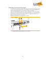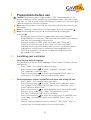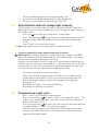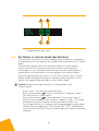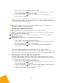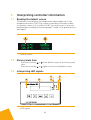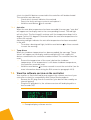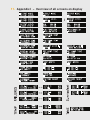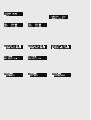
1
Gavita
GavitaMaster
MasterController
ControllerEL2
EL2
User manual
User manual
Gavita Master controller EL2
Dear Customer,
Congratulations on the purchase of your Gavita Master controller EL2.
This manual contains all the information necessary to install, use and maintain the
Gavita Master controller EL2. Please read and understand this manual completely
before installing and using the product.
Consult the index at the start of this manual to locate information relevant to you.
In this manual, the Gavita Master controller EL2 will be referred to as the controller.
This is the original manual, keep it in a safe location!
3
Table of contents
1.Introduction
1.1. Product description
1.2. Glossary of Terminology
1.3. Used symbols
7
7
8
8
2.
Product specifications
2.1. General product information
2.2. Technical specifications
2.3.Environment
2.4. Required tools
2.5. Components 2.6. Controls 2.7.Indications
2.8.Connections
2.9.Accessories
2.10. Compatible ballasts
9
9
9
9
9
10
10
11
12
13
13
3.
Safety guidelines and measures
14
4.
Installing the controller
4.1. Placing the controller
4.2. Installing and connecting the temperature sensor(s)
4.2.1. Installing the temperature sensor in “Follow mode” (one room) 4.2.2. Installing the temperature sensors in “Inverse mode” (two rooms) 4.3. Connecting the controller to the ballasts
4.3.1. Connecting the controller to remote ballasts
4.3.2. Connecting the controller to complete fixtures
4.3.3. Shortening RJ cables
4.4. Connecting the controller to External Contactor Modules (ECMs) to
control auxiliary equipment
4.4.1. Connecting the signal cable to the controller and the ECM(s)
4.4.2.Controlling auxiliary equipment in “Follow mode” (one room)
4.4.2.1.Connecting equipment which must be used during lights-on periods
4.4.2.2.Connecting equipment which must be used during lights-off periods
4.4.3.Controlling auxiliary equipment in “Inverse mode”
(two rooms 12h/12h) 4.4.3.1.Connecting equipment which must be used during lights-on periods
4.4.3.2.Connecting equipment which must be used during lights-off periods
4.5. Connecting a temperature shutdown, sensor failure or
power-off alarm to the controller 4.5.1. Connecting an alarm wire to the controller 4.6. Connecting the controller to the mains
14
14
15
16
17
18
18
19
20
4
20
21
22
22
23
23
24
24
24
25
26
5.
Preparations before use
27
5.1. Localizing your controller
27
5.1.1. Selecting your default language
27
5.1.2. Switching between 24 hour and AM/PM clock mode and
setting the time
27
5.1.3. Switch temperature units between 0Fahrenheit and 0Celsius28
5.2. Calibrating the temperature sensor(s)
28
5.3. Change the display mode from the controller output from % to Watts 29
6.
Programming and using the controller
6.1. Adjust ballast output to change light intensity
6.1.1. Control a lamp with a lower power rating then its ballast 6.2. Programming a light cycle
6.3. Set follow- or inverse mode (aux function) 6.4. Set temperature safety settings
6.4.1. Setting the auto-dim temperature 6.4.2. Setting safety shutdown temperature
6.5. Setting the sunrise and sunset period
6.6. Activate or deactivate the lights manually or set automatic mode
6.7. Resetting the controller to factory settings
30
31
31
31
32
33
33
34
34
35
35
7.
Interpreting controller information
7.1. Reading the default screen
7.2. Show system time
7.3. Interpreting LED signals
7.3.1. Green light (22A)
7.3.2. Blue light (22C/22D)
7.3.3. Red light (22E/22F)
7.4. Interpreting display messages
7.4.1. Sensor disconnected
7.4.2. Sensor failure
7.4.3. Controller Overload
7.4.4.Auto-dim
7.4.5. Temp Alarm
7.5. View the software version on the controller
36
36
36
36
37
37
37
37
37
37
37
38
38
38
8.
Maintenance and Repair 39
9.
Environment and Disposal 39
10. Warranty 39
11. Appendix I – Overview of all screens on display
40
5
1. Introduction
1.1. Product description
The Gavita Master controller EL2 is a dual channel controller which can
control up to 80 ballasts/lights in climate rooms.
Unlike a switchboard, which switches the power supply of regular ballasts
on and off, the controller can control appropriate Gavita e-series ballasts by
means of a low voltage control signal.
The controller has two channels; a main channel and an auxiliary channel.
Both channels can control a group of up to 40 e-series ballasts.
The controller can be set to activate and deactivate all ballasts connected
to it simultaneously. In this manual, this mode will be referred to as the
“Follow Mode”.
The controller can also be set to alternate between the main and auxiliary
channel. This means the auxiliary channel and the ballasts connected to it,
are switched off when the main channel and the ballasts connected to it are
switched on and vice versa. An inverted light cycle is intended to be used to
alternate light between two rooms in a 12/12 hour system, to optimize power
utilization. In this manual this mode will be referred to as the “Inverse Mode”.
The ballasts and lights connected to the controller form a significant heat
source within the climate room. If for whatever reason, the climate control
system cannot prevent the temperature from rising in the climate room, the
lights should be dimmed or even shut down to prevent crop damage.
The controller can be connected to either one temperature sensor (in
follow mode) or two temperature sensors (in inverse mode) to sense the
temperature in the climate room(s). The controller offers the possibility to set
the temperature at which it will dim the lights and a temperature at which it
will shut the lights down.
The controller is not meant to replace climate control equipment. Its autodim and shutdown function are primarily meant to prevent crop damage.
Besides controlling up to 80 ballasts, the controller can also control two
Gavita External Contactor Modules (ECMs). These modules can be used to
switch auxiliary equipment during light on or light off periods (CO2 equipment,
heating, cooling, etc). The ECMs may also be used to switch non-dimmable
supplemental lighting, such as the regular (non e-series) plasma lamps.
Auxiliary equipment is also governed by the controller’s temperature safety
features.
The controller is provided with a set of alarm contacts which may be
connected to a standard alarm installation or cell phone module to provide
7
instant messaging. An alarm will be triggered by temperature shutdown,
sensor failure or power failure.
The controller is equipped with a 16x2 character green OLED display, which
ensures high contrast and clarity in dark and light environments. It provides a
self-explaining menu system with a full text interface for extremely easy and
intuitive use. There is no need to go through a code table to set your controls
or read your statuses. The system is also equipped with LEDs as status
indicators to see the status of your controller at a glance.
The interface language is user selectable: English, Spanish, French, German
and Dutch are standard available.
The Controller uses a low DC voltage to control both ballasts and contactor
modules, making the system safe to install. Cables for plug & play
installation are provided with the controller and the ballasts.
1.2. Glossary of Terminology
ECM
EL
Light cycle
Lights-on period
Lights-off period
Follow mode
Inverse mode
Cage clamp
Ballast
Complete fixture
External Contactor Module
Entry level
A 24 hour period in which the lights are activated
and deactivated once
The period of the light cycle in which the lights are
activated
The period of the light cycle in which the lights are
not activated
Main and auxiliary channel are switched on and off
simultaneously
Main and auxiliary channel are switched
alternating (one on, one off and vice versa)
Wire clamp
A ballast is a device intended to ignite and power
HID lamps
A ballast integrated with a reflector and lamp
1.3. Used symbols
The following icons will be used throughout the manual:
Warning! A warning indicates severe damage to the user and/or product may
occur when a procedure is not carried out as described.
Caution! A caution sign indicates problems may occur if a procedure is not
carried out as described.
Note/Example: A note or example provides tips and addition information to
the user.
8
2. Product specifications
2.1. General product information
Product name
Product code
Producer
Master Controller EL2
60.56.00.xx.xx
Gavita Holland bv
Controller dimensions (LxWxH)
Weight
127 x 22 x 75 mm
170 gram
Adapter: 100V-240V AC 50/60hz 5V DC (2000mA)
11.5V
2.2. Technical specifications
Power supply
Maximum control voltage
Maximum voltage/current alarm
contacts (NO/NC)
Maximum cable length per port
Maximum number of ballasts per port
Total number of ballasts per controller
13,5V/50mA
100m (328ft)
40
80
2.3. Environment
Warning! The product may not be exposed to moisture, condensing humidity,
contamination or dust.
Temperature range
Operating humidity (non-condensing)
0-35 OC / 32 - 95 OF
<80%
2.4. Required tools
Task
Mounting controller
Mounting controller
Modify cable length (optional)
Tool
Screwdriver
Drill
RJ14 crimp tool
9
2.5. Components
E
I
F
I
II
G
A
B
C
D
A. Gavita Master controller EL2
I. Mounting plate
B. 2x Countersunk screw
C. 2x Plug
D. Manual
E. 120-240V AC - 5V DC power adapter (2000mA)
F. 2x Controller cable (5m/16ft)
I. RJ14 (6P4C) plug (connect to ballasts)
II. RJ9 (4P4C) plug (connect to controller)
G. 2x Temperature sensor with cable (5m/16ft)
2.6. Controls
A
A
B
C
D
E
Key
Quick-key
Down
Enter
Up
Back
B
C
D
E
Function
View and adjust output level
Navigate down in menu/decrease value
Go to menu/confirm
Navigate up in menu/increase value
Navigate back in menu/cancel/reset
10
2.7. Indications
A
C
D
B
E
F
For more information on indications go to chapter 7
Indication signal
A Power indication
B Display
Light indication
C
main
D
Light indication
aux
E
Temperature
warning main
F
Temperature
warning aux
Function
A burning green light indicates controller is active.
A blinking green light indicates a power interruption
has occured during operation.
Displays status, warnings and controller menu.
A burning blue light indicates the port is active.
A blinking blue light indicates an overload/short
circuit in a cable connected to the port.
Blue light off indicates the port is inactive.
A burning red light indicates the auto-dim
temperature has been exceeded in the past.
A blinking red light indicates the auto-dim
temperature threshold is currently exceeded. The
corresponding output channels are being dimmed.
A fast blinking red light indicates the shutdown
temperature threshold has been exceeded.
All output channels have been shut down.
11
2.8. Connections
A
A.
B.
C.
D.
E.
F.
G.
H.
I.
B
C
D E F G H
I
5V DC input
3,5 mm jack main temperature sensor (T1)
RJ9 (4P4C) Main port for controlling up to 40 ballasts
Cage clamp connector ECM1 (output is active when main channel is on)
Cage clamp connector ECM2 (output is active when main channel is off)
Cage clamp alarm Normally Open (potential free contact)
Cage clamp alarm Normally Closed (potential free contact)
RJ9 (4P4C) Auxiliary port for controlling up to 40 ballasts
3,5 mm jack auxiliary temperature sensor (T2)
12
2.9. Accessories
Note: Accessories are not included, they have to be bought separately. Visit
the website of Gavita Holland: www.gavita-holland.com for the latest Gavita
products.
Part
Interconnect cable
(RJ14-RJ14)
Controller cable
(RJ9-RJ14)
Three-way RJ14 Splitter
Power supply Gavita
Master Controller
EL1/EL2
(with 2 m cord,
universal voltage 120240 V)
ECM1 External
Contactor Module
(with 10 ft / 3 m cable)
ECM controller cable
3m/10 ft
Temperature sensor
(with 5 m cable - 3.5
mm mini jack plug)
Variants
2 ft / 0,60 m
5 ft / 1.5 m - standard cable
8 ft / 2.4 m
10 ft / 3.0 m
5 ft / 1.5 m
16 ft / 5 m - standard cable
25 ft / 7.5 m
Product code
60.50.00.08
60.50.00.04
60.50.00.09
60.50.00.10
60.50.00.11
60.50.00.12
60.50.00.13
60.50.00.01
US version 120V
90.02.02.03
UK version 240V
90.02.02.02
EU version 230V
90.02.02.01
AUS version 240V
US version 120V 15A
US version 240V 15A
UK version 240V 13A
EU version 230V 16A
AUS version 240V 10A
CH version 240V 10A
90.02.02.05
60,57,00,12,20
60,57,00,24,20
60,57,00,24,11
60,57,00,23,10
60,57,00,24,60
60,57,00,23,12
10 ft / 3.0 m standard cable
90.03.01.15
16 ft / 5.0 m cable length standard
60.50.00.14
2.10.Compatible ballasts
Note: Ballasts are not included, they have to be bought separately. Visit the
website of Gavita Holland: www.gavita-holland.com for the latest Gavita
products.
The Gavita Master controller EL2 is compatible with all Gavita e-series
ballasts.
13
3. Safety guidelines and measures
Warning! Keep the controller away from fire, excessive heat, water, dust and
contamination.
Warning! The Gavita Master controller EL2 may only be used to control
compatible Gavita e-series ballasts. Do not connect the Controller to other
products as this may be dangerous and may cause malfunctions in the
connected equipment. Doing so will void the warranty.
Warning! The ECM channels of the Gavita Master controller EL2 may only be
connected to Gavita ECMs. Do not connect the Controller to other products as
this may lead to malfunctions or damage and can be dangerous. Doing so will
void the warranty.
Warning! Do not open or disassemble the controller, it contains no
serviceable parts. Opening the controller will void its warranty.
4. Installing the controller
4.1. Placing the controller
Warning! The area in which the product is placed must comply with the
conditions specified in paragraph 2.3.
Caution! Only mount the product on a sturdy, solid background.
Note: Use the included plugs for hard surfaces.
•
•
Determine the optimal location for the controller
Carefully pry the mounting clamp from the controller using a prying tool
or a flat head screwdriver (1) (tape it to prevent damage to the housing).
1 Removing mounting clamp
14
•
•
•
Hang the controller mounting plate against the desired surface using
one of the a countersunk screws (2A)
Secure the mounting plate with a second screw (2B)
Click the controller on the mounting clamp (3).
A
B
2 Hanging the mouniting clamp
3 C
licking the controller on
the clamp
4.2. Installing and connecting the temperature sensor(s)
Warning! The Gavita Master controller is not a climate controller.
Do not use the product to manage the temperature in your climate room.
Caution! Only use Gavita temperature sensors.
Caution! Ensure the controller measures the same temperature as the
climate control system (see paragraph 5.2).
The controller can only be used when it is connected to either one or two
temperature sensors. The controller uses these sensors to monitor the
temperature in the climate room(s). The controller will automatically dim or
shut down the lights if the temperature in a climate room becomes too high.
For more information on temperature safety, consult paragraph 6.4.
The controller must be connected to ONE temperature sensor when the
controller is in “Follow mode”. (see paragraph 4.2.1) The controller must be
connected to TWO temperature sensors if the controller is in “Inverse mode”
(see paragraph 4.2.2).
15
4.2.1. Installing the temperature sensor in “Follow mode” (one room)
Only one of the provided temperature sensors is needed in “Follow mode”.
•
•
•
•
Place the provided temperature sensor as close as possible to the
sensor of the existing climate control system, so both sensors will
measure the same temperature (4A)
Ensure the sensor is covered from the light, as this will disrupt
temperature measurements. Use a hood if necessary (4B).
A template for a hood is included on the last page
Insert the plug of the temperature sensor into the T1 port (4C)
The temperature measured by the sensor will be displayed on the
controller display.
Climate control system
C
B
A
4 Placing a temperature sensor in “follow mode”
Note: The displayed temperature may take some time to level out.
Note: If the length of the sensor cable is insufficient to reach the controller,
try to relocate the controller. If this is not possible, the sensor cable may be
lengthened an extra 5 meters by using a standard 3,5 mm jack extension
cable. If the message “sensor removed” appears, the plug of the sensor is not
(fully) plugged in. Plug the sensor in completely.
Note: If the message “sensor failure” appears, the sensor is defect.
Replace the sensor.
16
4.2.2. Installing the temperature sensors in “Inverse mode” (two rooms)
Two temperature sensors are needed in “Inverse mode”.
• Before placing the temperature sensors, determine which controller
channel (main/aux) controls the lights in which room
(“main” room/“aux” room) (5)
• Place one temperature sensor in each room. Ensure both sensors are
placed as close as possible to the temperature sensors of the existing
climate control system (5A)
• Ensure the sensor is covered from the light, as this will disrupt
temperature measurements. (5B) Use a hood if necessary.
A template for a hood is included on the last page
• Insert the plug of the sensor placed in the “main” room (5C) in the T1
input of the controller
• Insert the plug of the sensor placed in the “aux” room (5D) in the T2
input of the controller
• The temperature measured by both sensors will be displayed on the
controller display.
Climate control system
Auxilliary Room
Climate control system
Main Room
C
D
Main
Room
Aux
Room
B
A
5 Placing a temperature sensor in “inverse mode”
Note: The displayed temperature may take some time to level out.
Note: If the length of the sensor cable is not long enough to reach the
controller, relocate the controller. If this is not possible, the sensor cable may
be lengthened an extra 5 meters using a standard 3,5 mm jack extension
cable. If the message “sensor removed” appears, the plug of the sensor is not
(fully) plugged in. Plug the sensor in completely.
Note: If the message “sensor failure” appears, the sensor is defect. Replace
the sensor.
17
4.3. Connecting the controller to the ballasts
Warning! The controller may can only be connected to compatible Gavita
e-series remote ballasts and complete fixtures. For a list of compatible
products, consult paragraph 2.10 or go to www.gavita-holland.com.
Note: for more information on shortening RJ cables, consult paragraph 4.3.3.
A group of up to 40 e-series ballasts can be connected to both the main RJ9
port and the auxiliary RJ9 port of the controller. Consult paragraph 4.3.1 to
connect the controller to remote ballasts. Consult paragraph 4.3.2 to connect
the controller to complete fixtures.
4.3.1. Connecting the controller to remote ballasts
Warning! When connecting the fixture to the controller it may ignite. Make
sure either fixture power is disconnected or the controller is switched off.
Warning! Ensure the remote ballasts are connected to their lamps and
reflectors.
•
•
•
•
Switch the rotary knob on all Gavita ballasts to “EXT” (external control)
Plug the RJ9 end of one of the controller cable(s) (6A) into the RJ9 main
port of the controller. If a two room setup is used or if more than 40
ballast have to be connected, plug a second ballast connection cable in
the RJ9 aux port (6B)
Plug the RJ14 end of the controller cable(s) into one of the two RJ14
ports of the first ballast (6C)
Interconnect the remote ballast to the next ballast in line using an
interconnect cable with RJ14 plugs (6D). Up to 40 ballasts may be daisy
chained this way.
A
D
B
C
Max 40 Ballast
Main Channel
Aux Channel
Max 40 Ballast
6 Connecting the controller to remote ballasts
18
4.3.2. Connecting the controller to complete fixtures
Warning! When connecting the fixture to the controller it may ignite. Make
sure either fixture power is disconnected or the controller is switched off.
Note: A RJ14 splitter and two cables are provided with each complete fixture
since complete fixtures have only one RJ14 port.
•
•
•
•
•
•
Switch the rotary knob on all Gavita ballasts to “EXT”
Plug the RJ9 end of one of the provided controller cable into the RJ9
main port of the controller (7A)
If a two room setup is used or if more than 40 ballast have to be
connected, plug a second controller cable in the RJ9 aux port (7B)
Plug the RJ14 end of the controller cable(s) (7C) into the input of a RJ14
splitter (7D). Use an interconnect cable to connect one output of the
RJ14 splitter to the RJ14 port of the ballast (7E)
Use an interconnect cable to connect one output of the RJ14 splitter to
the input of the following RJ14 splitter (7F)
Repeat this process to connect up to 40 ballasts per group.
F
E
A
B
D
C
F
E D C
Max 40 Ballast
Main Channel
Max 40 Ballast
Aux Channel
7 Connecting the controller to complete fixtures
19
4.3.3. Shortening RJ cables
Note: A RJ14 crimp tool is needed to shorten a RJ cable and install a RJ14
plug!
Note: Don’t remove RJ9 plugs unless you have a RJ9 crimp tool!
Caution! Always follow the instructions provided with the crimp tool!
• Shorten the cable on the desired length
• Strip the outer insulation off the RJ cable (8 mm). Leave the inner
insulation intact!
• Push the four wires into the middle openings of a RJ14 plug. The
orientation of the plug does not matter as long as the wires are entered
in the central four openings (8A).
Caution! If the wires are not inserted in the middle of the plug, the wires
will short circuit, when plugged into a ballast or complete fixture, causing a
controller overload (8B, see also paragraph 7.4.3).
• Crimp the RJ 14 plug on the RJ wire.
A
B
8 Wiring a RJ14 plug
4.4. Connecting the controller to External Contactor Modules
(ECMs) to control auxiliary equipment
Warning! ECMs can handle equipment with a resistive load (AC1) up to 16A.
The maximum allowable current can be limited by local type of plugs
(e.g. UK = 13A). Higher currents may be supported by using ECMs to trigger
heavier contactors.
Warning! To prevent over-current, always determine the maximum allowable
current for your (local) cabling before connecting a load to the ECM.
Warning! Never connect the cage clamps of the ECM to any other device than
the Gavita EL2 controller.
Warning! Never connect more then one ECM to each set of cage clamps of
the controller.
20
Warning! Ensure all wire ends are fully inserted into the cage clamps.
Exposed wire endings can be dangerous!
Caution! To prevent potential crop damage, ECMs are automatically
shut down after a temperature alarm, a sensor failure or during a power
interruption. This function only works in the “Auto” mode (see paragraph 6.6).
The Controller can control up to two External Contactor Modules. These ECM
modules are contactors and can activate or deactivate auxiliary equipment.
Auxiliary equipment may include a CO2 source or a non-dimmable light
during “lights-on” periods or for example a room heater during “lights off”.
The controller is connected to the ECM by means of a signal cable. This signal
cable is plugged into the cage clamps of the controller and the ECM.
The controller has two ECM ports marked “ECM1” and “ECM2”.
ECM port 1 follows the output of the main channel of the controller (on when
lights in main room are on). ECM port 2 works inverse of ECM port 1 and is
switched on when the main channel is off (on when when the lights in the
main room are off, in the dark period). For more information about connecting
ECMs to the controller, consult paragraph 4.4.2 and 4.4.3.
4.4.1. Connecting the signal cable to the controller and the ECM(s)
• Press the white buttons above the contact openings of the cage clamps
to open them (9A) (when using solid cable ends this is not required)
• Insert the endings of the included signal cable into the desired cage
clamps of the controller (9B). A cable of up to 20 meters may be used.
The endings need to be stripped 8mm and preferably be tinned or
finished with cable end sleeves
• Release the buttons to lock the wires in place
• Connect the wire to the cage clamps of the ECM in the same way (10).
MAX 8 mm
A
B
9 C
onnecting a signal cable to
the controller
10 C
onnecting a signal cable to
the ECM
Note: For more information on connecting an ECM to the auxiliary equipment,
consult the ECM manual.
21
4.4.2. C
ontrolling auxiliary equipment in “Follow mode” (one room)
Caution! Gavita recommends you install and connect the ECM before
plugging it into the mains.
Note: When activated, the blue light on the ECM will burn.
ECM1
A
ECM2
1
B
2
Main
Auxiliary
equipment
(lights on)
Auxiliary
equipment
(lights off)
11 Controlling auxiliary equipment in “Follow mode”
4.4.2.1.Connecting equipment which must be used during lights-on periods
Example: a CO2 source, light or watering unit may be activated during
lights-on periods.
• Connect the ECM to the cage clamps marked “ECM1”(11A)
• Plug the auxiliary equipment into the female plug of the ECM power
cords
• Plug the ECM male plug into a mains receptacle.
22
4.4.2.2.Connecting equipment which must be used during lights-off periods
Example: a heater may be activated during lights-off periods.
• Connect the ECM to the cage clamps marked“ECM2”(11B)
• Connect the auxiliary equipment which must be activated during
lights-off periods to the ECM connected to clamps marked “ECM2”.
4.4.3. C
ontrolling auxiliary equipment in “Inverse mode” (two rooms 12h/12h)
Caution! Gavita recommends you install and connect the ECM before
plugging it into the mains.
Note: Two ECMs are needed for a two room setup.
Note: When activated, the blue light on the ECM will burn.
• Link one ECM to the controller cage clamps marked “ECM1” and a
second ECM to the controller cage clamps marked “ECM2”.
A
ECM1
ECM2
1
B
2
Main
Room
Aux
Room
Auxiliary
equipment
(lights on)
Auxiliary
equipment
(lights off)
Auxiliary
equipment
(lights on)
Auxiliary
equipment
(lights off)
12 Controlling auxiliary equipment in “Inverse mode”
23
4.4.3.1.Connecting equipment which must be used during lights-on periods
Example: a CO2 source, light or watering unit may be activated during
lights-on periods.
• Connect the auxiliary equipment in the “main” room which must be
activated during lights-on periods to the ECM connected to clamps
“ECM1” (12A)
• Connect the auxiliary equipment in the “aux” room which must be
activated during lights-on periods to the ECM connected to clamps
“ECM2” (12B).
4.4.3.2.Connecting equipment which must be used during lights-off periods
Example: a heater may be activated during lights-off periods.
• Connect the auxiliary equipment in the “main” room which must be
activated during lights-off periods to the ECM connected to clamps
“ECM2” (12B)
• Connect the auxiliary equipment in the “aux” room which must be
activated during lights-off periods to the ECM connected to clamps
“ECM1” (12A).
4.5. Connecting a temperature shutdown, sensor failure or
power-off alarm to the controller
Warning! The alarm feature only works in the “auto” mode
(see paragraph 6.6).
Warning! The alarm contacts are rated for a maximum of 13,5V/50mA.
The controller has two pairs of cage clamps marked “A-NC” (normally closed)
and “A-NO” (normally open).
When a temperature shutdown, sensor failure, or power failure occurs, the
“A-NC” contact opens and the “A-NO” contact closes. Both pairs of cage
clamps may be connected to an alarm installation or a text messaging
module.
24
4.5.1. Connecting an alarm wire to the controller
• To connect an alarm to a cage clamp, take the wire from the alarm, split
it in two and strip the ends bare. The endings need to be stripped 8mm
and preferably be tinned or finished with cable end sleeves
• Press the white buttons above the contact openings of the cage clamps
under A-NC or A-NO (when using solid cable ends this is not required)
• Insert both wire ends of the alarm system in a separate opening, the
polarity of the wires does not matter
• Release the buttons to lock the wires in place.
A B
C
13 Connecting the alarm wire to the controller
25
4.6. Connecting the controller to the mains
Warning! When you power on the controller, the connected ballasts may
ignite. Either:
a) make sure your ballasts are not connected to mains yet or
b) the signal cable of the ballasts is not inserted in the controller yet
before connecting and programming the controller.
•
•
•
Plug the adapter into the AC outlet
Plug the DC connector of the adapter into the DC inlet of the controller.
(14A) The green power indication (14B) will start blinking, to indicate the
power was interrupted
Hold the reset button for 3 seconds. The green power indication will
start to burn continuously.
B
A
14 Connecting the controller to the mains
26
5. Preparations before use
Caution! Set the controllers output mode to “OFF” (see paragraph 6.6.) to
ensure no ballasts will be accidentally activated during the controller setup.
After this it is safe to either connect the ballasts to mains or insert the signal
cable to the ballasts into the controller.
Note: after 60 seconds of inactivity the controller interface will return to the
main menu.
Note: to leave any screen without saving changes, press the arrow key .
Note: lesser used functions can be accessed faster by clicking the
arrow key .
• Ensure you have carried out all applicable steps from chapter 4
• Plug the ballast in the mains. The status led on the ballast will indicate
that they are connected to the controller
• Examine whether all LEDs show the correct code. Check the
connections when you see an error code. In case an overload is
indicated on the controller display please check if you did not make a
cabling error connecting a RJ connector (see paragraph 4.3.3.)
• Verify your controller is ready for use by performing the actions
described in this chapter.
5.1. Localizing your controller
5.1.1. Selecting your default language
The controller can be set to five languages: Dutch, English, German, French
and Spanish.
• Press “enter”, the controller menu will open
• Press the arrow keys
to locate “language” and press “enter”.
The “language” screen will open
• Press the arrow keys
to locate your language. Press “enter” to
confirm your choice and return to the controller menu.
5.1.2. Switching between 24 hour and AM/PM clock mode and setting the time
• Press “enter”, the controller menu will open
• Press the arrow keys
to locate “System time” and press “enter”.
The “System Time” screen (15) will open. In this screen the “clock
mode” indication blinks (15A)
• Press the arrow keys
to switch between the 24-hour and the AM/
PM-hour clock mode. Press “enter” to confirm your choice.
The “hour” indication (15B) will start blinking
• Press the arrow keys
to select the correct hour. In a AM/PM-hour
clock mode, continue pressing to select AM/PM. Press “enter” to
confirm.
• Use the same procedure to set the “minutes” (15C). Press “enter” to
confirm your choice and return to the controller menu.
27
A
B
C
15 Switching clock mode and setting the time
5.1.3. Switch temperature units between 0Fahrenheit and 0Celsius
• Press “enter”, the controller menu will open
• Press the arrow keys
to locate “Temp units” and press “enter”.
The “temperature units” screen will open
• Press the arrow keys
to switch between 0F and 0C. Press “enter” to
confirm your choice and return to the controller menu.
5.2. Calibrating the temperature sensor(s)
Caution! The controller will not immediately display the correct temperature
when the sensor is plugged in. The sensor will take some time to respond to
temperature changes.
Caution! To allow for accurate temperature management within the
climate room, the temperature measured by the controller must match the
temperature measured by the climate control system. If these values do not
match, the temperature safety system of the Gavita controller may interfere
with the climate control system.
Caution! Always place the temperature sensor of the controller as close as
possible to the temperature sensor of the climate control system.
If necessary, the temperature measured by the Gavita controller can be
adjusted to match the temperature measured by the climate control system.
• Press “enter”, the controller menu will open
• Press the arrow keys
to locate “Calibrate” and press “enter”.
The “Calibration” screen will open (16). This screen displays the temperature
measured by the main temperature sensor “T1” (16A) and auxiliary
temperature sensor“T2” (16B). If one or both temperature sensors are not or
incorrectly connected, the text “removed” or “failure” will be displayed behind
the applicable temperature sensor.
28
A
B
16 Calibrating the temperature sensor
•
•
to switch between “T1” or “T2” and press
Use the arrow keys
“enter” to select the temperature value you wish to adjust
to adjust the temperature to the desired value
Use the arrow keys
and press “enter” to confirm your choice.
Note: The calibrated temperature values are stored in the internal memory
of the controller. Resetting the controller will restore these values (see
paragraph 6.7).
5.3. Change the display mode from the controller output
from % to Watts
Caution! The wattage displayed by the controller only serves as a visual aid,
calculating the output in wattage from the set percentage. If a 400W ballast
model is selected in the controller but a 1000W ballast is connected, the
ballast will still provide a 1000W output at 100%.
Warning! Always use the % setting when ballasts with different wattages are
used simultaneously.
By default the controller represents ballast output as a percentage of the
total output (17A). The controller can also convert this percentage into Watts
if the wattage of the ballast is known.
29
A
17 Default output display
•
•
Press “enter”, the controller menu will open
to locate “Display mode” and press “enter”.
Press the arrow keys
The “Display mode” screen opens
• Press the arrow keys
to select which type of ballasts you have
connected: 400W, 600W, 750W, 1000W, or select percentage in a mixed
environment
• Press “enter”to confirm your choice.
The “main” screen and the “output level” screen (see paragraph 6.1) will now
represent the ballast output in Watts (18B).
B
18 Output display in Watts
6. Programming and using the controller
Caution! Set the controllers output mode to “OFF” (see paragraph 6.6.) to
ensure no ballasts will be accidentally activated during the controller setup.
Follow the actions listed below to quickly start using the controller.
• Set the controller output level (see paragraph 6.1)
• Program a light cycle (see paragraph 6.2)
• Set the output mode of the controller to “follow” or “inverse”
(see paragraph 6.3)
• Set the auto-dim temperature (see paragraph 6.4.1)
30
•
•
•
Set the shutdown temperature (see paragraph 6.4.2)
Set sunrise/sunset period (optional) (see paragraph 6.5)
Activate the auto mode on the controller (see 6.6.).
6.1. Adjust ballast output to change light intensity
The controller can set the output of a ballast between 50 and 115 percent.
Adjusting this ballast output enables the user to change the light intensity in
the climate room.
• Press the quick-key, the “output level” screen opens
• Press the arrow keys
to set the ballast output between 50 and 115
percent (400W, 600W and 750W fixtures can only be boosted up tot
110%)
• Press “enter” to confirm your choice.
Note: the output level can also be found in the general menu.
6.1.1. Control a lamp with a lower power rating then its ballast
Warning! When fitting a lamp with a lower output then its ballast, ALWAYS
adjust the output level of the ballast before switching the light on. Failing to
do will cause immediate damage to the lamp.
A ballast may be used to control a lamp with a lower power output then the
nominal value of the ballast. For example: a 1000 watt ballast set at 750 watt
can be used to control a 750 watt lamp. To prevent damage to the light, the
controller output must be adjusted to the appropriate value.
•
•
•
•
•
Disconnect the ballast(s) from the mains
Make sure the display mode of the controller is set to represent the
output power of your ballast, NOT of your lamp (see paragraph 5.3)
Adjust the ballast output to match the wattage of the lamp (see
paragraph 6.1)
Exchange the lamps of all connected ballasts
Reconnect the ballast to the mains.
6.2. Programming a light cycle
•
•
•
•
Press “enter”, the controller menu will open
to locate “Light Cycle” and press “enter”. The
Press the arrow keys
“Light Cycle” screen will open. (19) In this screen the hour indication
behind “ON” blinks (19A)
Press the arrow keys
to select the hour on which the lights must be
activated and press “enter” to confirm your choice.
Use the same procedure to set the minute (19B) on which the lights
must be activated and the hour (19C) and minute (19D) on which the
lights must be deactivated.
31
A
B
C
D
19 Programming a light cycle
6.3. Set follow- or inverse mode (aux function)
The controller can be set to activate and deactivate all ballasts connected to
it simultaneously. In this manual, this mode will be referred to as the “Follow
Mode”.
The controller may also be set to invert the output of its main and the
auxiliary channel. This means the auxiliary channel and the ballasts
connected to it, are switched off when the main channel and the ballasts
connected to it are switched on. An inverted light cycle may be used to
alternate light between two rooms in a 12/12 hour system. Such a system
may be used in the generative phase to optimize power utilization. In this
manual this mode will be referred to as the “Inverse Mode”.
Caution! Always set the light interval to 12 hour periods in the
“Inverse mode”.
•
•
•
•
•
Press “enter”, the controller menu will open
Press the arrow keys
to locate “Aux function” and press “enter”.
The “Aux Function” screen opens.
Press the arrow keys
to switch between “follow” and “inverse”.
For the “Inverse mode”, select “inverse” and press “enter”. The output
of the Aux channel will now be off when the main channel is on.
Set the light interval to 12 hour periods (see paragraph) to ensure both
climate rooms are equally lit. The selected “ON”-“OFF” period will be
set for the main channel. (The aux channel operates inverse of the main
channel).
32
6.4. Set temperature safety settings
When the temperature in a climate room gets above a certain value, the
planted crops will start to degrade. If this rise in temperature occurs, it is
desirable to dim or shut down the lights in the climate room to reduce the
temperature in the room.
The controller offers the possibility to set a temperature at which it will dim
the lights and a temperature on which it will shut down the lights. Through its
temperature sensors, it can sense when a harmful temperature is reached.
To set the auto-dim temperature, go to paragraph 6.4.1. To set the shut-down
temperature, go to paragraph 6.4.2.
6.4.1. Setting the auto-dim temperature
Note: The default auto-dim temperature is set at 30 0C / 86 0F.
Note: The auto-dim temperature cannot be set higher than the shutdown
temperature.
Note: The auto-dim will decrease the light intensity to 50% over a span of two
degrees Celsius or 3,6 degrees Fahrenheit (20)
Warning! Always set the auto-dim temperature at least two degrees Celsius /
3,6 degrees Fahrenheit above the temperature of the climate control system.
This will prevent the controller from interfering with the climate control
system.
Output level
100%
50%
Temperature
Auto dim
temperature
2 degrees Celcius
3,6 degrees Fahrenheit
20 Auto-dim and shutdown behavior
33
Shutdown temperature
•
•
•
•
Press “enter”, the controller menu will open
Press the arrow keys
to locate “Auto-Dim Temp” and press “enter”.
The auto-dim temperature screen opens
Press the arrow keys
to increase or decrease the temperature.
Press “enter” to confirm.
Once the auto-dim temperature is reached, the controller will automatically
start dimming the lights. No auto-dim will occur if the shutdown temperature
is set at the auto-dim temperature.
Note: the auto-dim will stay on until half a degree Celsius / 0,9 degrees
Fahrenheit under the set temperature.
6.4.2. Setting safety shutdown temperature
Note: The default shutdown temperature is set at 35 0C /95 0F.
Note: The safety shutdown temperature of the controller cannot be set lower
than the auto-dim temperature.
Warning! Always set the shutdown temperature so it does not accidentally
deactivate the lights.
Warning! After a shutdown, a manual reset is required.
•
•
•
•
Press “enter”, the controller menu will open
Press the arrow keys
to locate “Shutdown Temp” and press “enter”.
The “Shutdown temperature” screen opens
Press the arrow keys
to increase or decrease the temperature.
Press “enter” to confirm.
Once the shutdown temperature is reached (20), the controller will
automatically shut down all the lights and all the equipment connected to the
ECMs. The A-NC and A-NO alarm contacts will also switch (see paragraph 4.5).
6.5. Setting the sunrise and sunset period
To allow crops to adjust to either a lights-on or lights-off period, a sunrise
and sunset period may be set. During this period, the light intensity increases
from 50 percent to up to the desired intensity.
• Press “enter”, the controller menu will open
• Press the arrow keys
to locate “Sunrise/sunset” and press “enter”.
The “Set ramp time” screen opens
• Press the arrow keys
to increase the ramp up/down time to up to 30
minutes. 0 minutes indicates no ramp up/down time
• Press “enter” to confirm your choice.
34
6.6. Activate or deactivate the lights manually or set
automatic mode
Warning! When replacing a light, setting the ballast to “Off” to override the
clock is insufficient! ALWAYS disconnect the ballast from the mains.
Warning! When the controller “Output mode” is set to “on” or “off”, the
temperature safety features of the controller will not work.
Note: The on and off mode are included to allow for replacement of ballasts
and testing of lamps.
•
•
•
•
Press “enter”, the controller menu will open
Press the arrow keys
to locate “Output mode” and press “enter”
Press the arrow keys
to switch between “auto”, “on” and “off”
-- Select “on” to turn all the lights on. This setting will ignore
temperature safety settings. (see paragraph 6.4)
-- Select “off” to turn all the lights off
-- Select “auto” to follow the programmed light cycle (see paragraph
6.2) and temperature safety settings (see paragraph 6.4)
Press “enter” to confirm your choice.
6.7. Resetting the controller to factory settings
The factory reset will return all values to factory settings. It will also undo any
changes to the temperature calibration of the temperature sensors.
•
•
•
Press “enter”, the controller menu will open
Press the arrow keys
to locate “Factory Reset” and press “enter”.
The “Factory Reset” screen opens
to switch to “yes” and press “enter”.
Press the arrow keys
The controller is now reset to factory settings.
35
7. Interpreting controller information
7.1. Reading the default screen
The default screen displays the temperature measured by one or two
temperature sensors (21A). The screen also displays the output of both
its channels, either in % or in Watts (21B). If an error occurs, it may also
be displayed in the display. (See paragraphs 7.3 and 7.4 for potential error
messages).
A
B
21 Default screen
7.2. Show system time
•
•
Press an arrow key
time
Press an arrow key
or
in the default screen to show the system
or
again to return to the default screen.
7.3. Interpreting LED signals
A
C
D
B
22 LED signals
36
E
F
7.3.1. Green light (22A)
A burning green light indicates the controller is functioning.
A blinking green light indicates the power has been interrupted.
After a power failure the blinking green indicator must be reset;
• Hold the reset button for three seconds to reset the indicator.
7.3.2. Blue light (22C/22D)
A burning blue light indicates the ballasts connected to the “main” and/or
“aux” channel are activated.
A blinking blue light indicates an overload in the main or aux channel
(see paragraph 7.4.3).
When a blue light is off, it indicates the connected ballasts are deactivated.
7.3.3. Red light (22E/22F)
A blinking red light indicates the auto-dim temperature is exceeded
(see paragraph 7.4.4).
A fast blinking red indicates the shutdown temperature has been exceeded
(see paragraph 7.4.5).
A burning red light indicates the auto-dim temperature has been exceeded in
the past (see paragraph 7.4.4).
7.4. Interpreting display messages
7.4.1. Sensor disconnected
The message “Sensor disconnected” appears when one or two temperature
sensors are not plugged in. All devices connected to the controller are
deactivated.
• Plug in the missing sensor to resolve.
7.4.2. Sensor failure
If the message “sensor failure” appears, the sensor is defect. All devices
connected to the controller are deactivated. The controller must be reset.
• Replace the temperature sensor
• Hold the reset button for 3 seconds.
7.4.3. Controller Overload
If the message “controller overload” appears, either the main or aux channel
of the controller has been overloaded. The blue led indicator behind the
overloaded channel will also start flashing. An overload may occur when
the wiring connected to the main or aux channel of the controller has
37
short circuited. All devices connected to the controller will be deactivated.
The controller must be reset;
• Check which channel indicates the overload
• Search for faulty wiring or contacts and replace it
• Hold the reset button for 3 seconds.
7.4.4. Auto-dim
When the auto-dim temperature has been exceeded, the message “auto dim”
will appear on the display next to the corresponding channel. The red light
will also flash. The flashing will continue until the temperature drops half a
degree Celsius/ 0.9 degrees Fahrenheit below the auto-dim temperature for
at least 30 seconds.
A burning red light indicates the auto-dim temperature has been exceeded
in the past.
• To resolve a burning red light, hold the reset button for three seconds
to reset the warning.
7.4.5. Temp Alarm
When the shutdown temperature has been exceeded, the message “Temp
alarm” will appear on the display and the red light will flash rapidly. All
devices connected to the controller are deactivated. The controller must be
reset;
• Ensure the temperature of the room is below the shutdown
temperature. If the temperature is still above shutdown temperature,
the controller cannot be reset
• Hold the reset button for three seconds to reset the controller (see for
more information about wiring the RJ4 connector paragraph 4.3.3).
7.5. View the software version on the controller
Your reseller or Gavita Holland bv may request the software version of your
controller to check for compatibility with (future) Gavita products.
• Remove the DC plug from the controller (your data will be saved by an
internal battery)
• Plug the DC plug back in, the software version will be displayed for a
few seconds (23).
23 Example display software version
38
8. Maintenance and Repair
Warning! Do not open or disassemble the controller, it contains no
serviceable parts. Opening the controller will void its warranty.
Warning! Do not use acids, solvents, abrasives or other aggressive
substances to clean the controller as this may cause damage.
The Gavita Master controller EL2 is maintenance free.
• The Controller may be cleaned with a soft dry cloth
• Please contact your reseller in case of controller malfunction.
9. Environment and Disposal
ATTENTION: THIS PRODUCT CONTAINS A BATTERY.
MUST BE DISPOSED OF PROPERLY.
The symbol on the material, accessories or packaging
indicates that this product may not be discarded as household
waste. Dispose of the equipment through a recycling center
that handles electronics and electrical appliances within
the EU and in other European countries which use separate
collection systems for used electronics and electrical
appliances. By disposing of the equipment in the proper
way, you will be helping to prevent possible risks to the environment and
public health, which might otherwise be caused by improper handling of the
discarded equipment. Recycling of materials contributes to the conservation
of natural resources. Therefore, please do not dispose of your old electronics
and electrical appliances via household waste.
10. Warranty
Gavita Holland warrants the mechanical and electronic components of their
product to be free of defects in material and workmanship if used under
normal operating conditions for a period of two (2) years from the original
date of purchase. If the product shows any defects within this period and
that defect is not due to user error or improper use Gavita Holland shall,
at its discretion, either replace or repair the product using suitable new or
reconditioned products or parts. In case Gavita Holland decides to replace the
entire product, this limited warranty shall apply to the replacement product
for the remaining initial warranty period, i.e.two (2) years from the date of
purchase of the original product. For service return the product to your shop
with the original sales receipt.
39
11. Appendix I – Overview of all screens on display
40
42
43