1
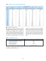
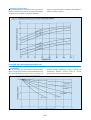
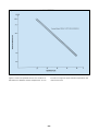
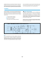
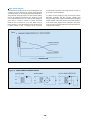
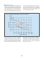
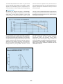
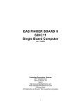
YUASA
Yuasa Battery Sales (U.K) Limited, Hawksworth Industrial Estate, Swindon, Wiltshire SN2 1EG
Telephone: Swindon (01793) 645700 Fax: (01793) 645701 e-mail: [email protected] Website: www.yuasa-battery.co.uk
Yuasa Battery (Europe) GMBH, Wanheimer Str. 47, D-40472 Düsseldorf, Germany
Telefon: 0049 211 417900 Fax: 0049 211 4179011
Issue Date 01.12.99
YUASA
YUASA
NP
VALVE REGULATED
LEAD ACID BATTERY
MANUAL
INTRODUCTION
Yuasa began development of the NP series of valve
regulated lead acid batteries in 1958. Today’s NP battery
is the culmination of over 75 years of battery
manufacturing experience.
The high energy density, advanced plate technology,
sealed construction, efficient performance and long
service life combine to make Yuasa NP batteries the most
reliable and versatile valve regulated lead acid batteries
available.
ADVANCEMENTS
With the progress of modern technology and the specific
development of application requirements, Yuasa has
designed generic NP’s to be application specific with the
introduction of NPC, NPH and NPL product ranges.
watts per kilo than conventional NP models when operated
at the 10 minute discharge rate.
NPL Offers up to double the float service life of the conventional NP type battery. Note, these models are available to
BS6290pt4 (1997).
NPC is specifically designed to suit the arduous requirements of cyclic applications allowing increased cycle life (at
least double the cyclic life of conventional types).
The generic types utilise identical physical designs and
characteristics to the standard NP type in all aspects except
their specific application advancement. This in many cases
allows users to upgrade without major redesign.
NPH These high performance batteries are specifically
designed for applications requiring high rate discharge and
offer much improved power densities up to 50% more
TECHNICAL FEATURES
•
Sealed Construction . . . . . . . . . . . . . .
Yuasa’s unique construction and sealing technique ensures that no electrolyte
leakage should occur from the terminals or case of any NP battery. This
feature provides for safe and effective operation of NP batteries in any
orientation. Yuasa NP batteries are classified as “Non-Spillable” and meet
all requirements of the International Air Transport Association. (I.A.T.A.
Dangerous Goods Regulations), to allow transportation by air.
•
Electrolyte Suspension System
All Yuasa NP batteries utilise an electrolyte suspension system consisting of
a glass fibre separator material. This suspension system helps to achieve
maximum service life, by fully retaining the electrolyte and preventing its escape
from the separator material. No silica gels or other contaminents are used.
•
Gas Generation . . . . . . . . . . . . . . . . .
NP batteries incorporate a unique Yuasa design that effectively recombines
over 99% of the gas generated during normal usage.
•
Low Maintenance Operation . . . . . . .
During the life of NP batteries, there is no need to check their specific gravity
or add water etc. In fact, there are no provisions for such maintenance
functions to be carried out.
•
Operation In Any Orientation . . . . . .
The combination of sealed construction and Yuasa’s electrolyte suspension
system permits operation of NP batteries in any orientation (excluding continuous
inverted use) without loss of capacity, electrolyte, or service life. The NP batteries
made in our factory in Wales also conform to BS EN61056-1 (1993) and IEC 10561 (1991).
•
Low Pressure Venting System . . . . .
Yuasa NP batteries are equipped with a safe, low pressure venting system,
which is designed to release excess gas and reseal automatically in the event of
the internal gas pressure rising to an unacceptable level. This low pressure
venting system, coupled with the significantly high recombination efficiency,
make Yuasa NP batteries one of the safest valve regulated lead acid batteries
available.
•
Heavy Duty Grids . . . . . . . . . . . . . . .
The heavy duty lead calcium alloy grids in NP batteries provide an extra
margin of performance and service life in both float and cyclic applications,
even in conditions of deep discharge.
•
Cyclic Service Life . . . . . . . . . . . . . . .
Depending upon the average depth of discharge, over 1,000 discharge/
recharge cycles can be expected from NP batteries.
•
Float Service Life . . . . . . . . . . . . . . . . .
The expected service life of the standard model NP battery when used in standby applications is typically 5 years; however, experience has shown that their
service life often exceeds 6 years, if the NP batteries are operated strictly within
specification.
–1–
•
Low Self Discharge -Long Shelf Life .
At temperatures of between 20 & 25˚c, the self discharge rate of NP batteries
per month is approximately 3% of their rated capacity. This low self discharge
rate permits storage for up to one year without any appreciable deterioration
of battery performance.
•
Operating Temperature Range ...........
Yuasa NP batteries can be used over a broad range of ambient temperatures,
allowing considerable flexibility in system design and location.
•
High Recovery Capability ....................
Yuasa NP batteries have excellent charge acceptance and recovery capability,
even after very deep discharge.
•
Quality Assurance ................................
Our U.K. manufacturing plant now has Quality Assurance Standard BS5750
Part 2 EN2900, ISO 9002 together with the M.O.D. Quality Assurance AQAP 4.
APPLICATIONS
A list of some of the more common applications for standby or principal power is given below:
•
•
•
•
•
•
•
•
•
•
•
•
•
•
•
•
•
•
•
•
•
Alarm Systems
Cable Television
Communications Equipment
Computers
Control Equipment
Electronic Cash Registers
Electronic Test Equipment
Emergency Lighting Systems
Fire & Security Systems
Geophysical Equipment
Marine Equipment
Medical Equipment
Microprocessor Based Office machines
Portable Cine & Video Lights
Power Tools
Solar Powered Systems
Telecommunication Systems
Television & Video Recorders
Toys
Uninterruptible Power Supplies
Vending Machines
YUASA NP BATTERY CONSTRUCTION
Terminals
Relief Valve
Top Cover
Cover
Sealant
Negative Plate
Container
Electrolyte
Retentive
Separator
Positive Plate
–2–
GENERAL SPECIFICATIONS
Nominal
Voltage
Nominal
Capacity (Ah)
Dimensions
Weight
Approx
(Kg)
Layout
(V)
(20Hr.)
(10Hr.)
L(mm)
W(mm)
Height over
Terminals (mm)
NP4.2-4H
4
4.4
4.20
48
35.5
119
0.56
6
Flat
NP10-4
4
10.0
9.25
102
50
98
1.35
1
D
NP1-6
6
1.0
0.93
51
42.5
54.5
0.25
5
A
NP1.2-6
6
1.2
1.11
97
25
54.5
0.31
1
A
NP2.8-6
6
2.8
2.60
134
34
64
0.57
1
A
NP3-6
6
3.0
2.78
134
34
64
0.63
1
A
NP4-6
6
4.0
3.70
70
47
105.5
0.87
5
A
NP7.6
6
7.0
6.48
151
34
97.5
1.32
1
A
NP10-6
6
10.0
9.25
151
50
97.5
1.98
1
A&C
NP12-6
6
12.0
11.10
151
50
97.5
2.05
1
C
NPL130-6
6
130.0
120.25
350
166
174
23.00
5
K
NP0.8-12
12
0.8
0.74
96
25
61.5
0.35
9
I
NP1.2-12
12
1.2
1.11
97
48
54.5
0.58
3
A
NP2-12
12
2.0
1.85
150
20
89/85
0.70
10
B
NP2.1-12
12
2.1
1.90
178
34
64
0.82
1
A
NPH2-12FR
12
-
2.00
68
51
88
0.84
2
A
NP2.3-12
12
2.3
2.13
178
34
64
0.95
1
A
NP2.8-12
12
2.8
2.60
134
67
64
1.12
3
A
NP3.2-12
12
3.2
3.00
134
67
64
1.2
4
A
NPH3.2-12
12
-
3.20
134
67
64
1.40
3
A
NP4-12
12
4.0
3.70
90
70
106
1.75
1
A&C
NPH5-12
12
-
5.00
90
70
106
2.00
1
D
NP7-12
12
7.0
6.48
151
65
97.5
2.65
4
A&C
NP12-12
12
12.0
11.10
151
98
97.5
4.05
4
D
NP17-12
12
17.0
13.88
181
75
167
6.1
2
J&E
NPH16-12
12
-
16.00
181
76
167
6.20
2
E
NP24-12
12
24.0
22.20
166
175
125
9.0
2
J&E
12
38.0
35.15
197
170
14.2
2
J&F
12
65.0
60.13
350
174
23.0
2
K&G
12
78.0
72.15
380
166
174
27.5
2
K&L
12
100.0
92.00
407
172.5
240
39
1
M10
Model
NP38-12
NP65-12
NPL78-12
NPL100-12
165
166
–3–
Terminals
bolt
Table 2. LAYOUT
Table3. TERMINALS
–4–
BATTERY CAPACITY SELECTION
Figure 2 below may be used to determine the minimum
battery size, expressed in Ampere hours of capacity. To
determine the required minimum battery capacity, plot
the required discharge current, on the horizontal
axis, against time. The point where the current and time
lines intersect on or below the diagonal Ah curve shows
the minimum capacity required for the application. In
practice, if the intersection point of the time & current
does not fall exactly on a particular Ah curve, the next
higher value Ah curve should be used to determine the
minimum battery capacity/size. In addition, it is
recommended that figure 32 (Cyclic Service Life) and
Figure 33 (Float Service Life) and if appropriate, the
constant power calculations in table 5, on page 7, should
be consulted prior to final selection.
FIG 2
DISCHARGE
Discharge Characteristics
The curves shown in Figure 3 and the discharge
current rates shown in Table 4 illustrate the
typical discharge characteristics of Yuasa NP batteries
at an ambient temperature of 25°. The symbol “C”
expresses the nominal capacity of the battery measured
at a 20-Hour discharge rate. Please refer to General
Specifications on page 3 to determine the nominal
capacity rating of specific NP models. The standard
industry practice to determine the nominal capacity of a
valve regulated lead acid battery is to discharge the battery
under test at its 20-Hour rate to a final voltage of 1.75
volts per cell.
Table 4 shows the different currents that can be drawn
at various discharge capacity rates.
Table 6 shows that the rated nominal capacity of a
battery is reduced when it is discharged at a value of
current that exceeds its 20-Hour discharge rate. This
should be taken into consideration when a battery is
being selected for a particular application.
–5–
Table 4. DISCHARGE CURRENT AT STIPULATED DISCHARGE RATES
Discharge Current
20 Hr.
Capacity
0.8 Ah
1.0
1.2
2.1
2.0
2.3
2.8
3.0
4.0
6.0
7.0
8.0
10.0
12.0
17.0
24.0
38.0
65.0
78.0
130.0
0.05C
0.04 A
0.05
0.06
0.105
0.10
0.115
0.14
0.15
0.20
0.30
0.35
0.40
0.50
0.60
0.85
1.20
1.90
3.25
3.90
6.50
0.1C
0.08 A
0.10
0.12
0.21
0.20
0.23
0.28
0.30
0.40
0.60
0.70
0.80
1.00
1.20
1.70
2.40
3.80
6.50
7.8
13.00
0.2C
0.16A
0.20
0.24
0.42
0.40
0.46
0.56
0.60
0.80
1.20
1.40
1.60
2.00
2.40
3.40
4.80
7.60
13.00
15.60
26.00
0.4C
0.32A
0.40
0.48
0.84
0.80
0.92
1.12
1.20
1.60
2.40
2.80
3.20
4.00
4.80
6.80
9.60
15.20
26.00
31.20
52.00
–6–
0.6C
0.48 A
0.60
0.72
1.26
1.20
1.38
1.68
1.80
2.40
3.60
4.20
4.80
6.00
7.20
10.20
14.40
22.80
39.00
46.80
78.00
1C
0.8A
1.0
1.2
2.1
2.0
2.3
2.8
3.0
4.0
6.0
7.0
8.0
10.0
12.0
17.0
24.0
38.0
65.0
78.0
130.0
2C
1.6A
2.0
2.4
4.2
4.0
4.6
5.6
6.0
8.0
12.0
14.0
16.0
20.0
24.0
34.0
48.0
76.0
130.0
156.0
260.0
3C
2.4 A
3.0
3.6
6.3
6.0
6.9
8.4
9.0
12.0
18.0
21.0
24.0
30.0
36.0
51.0
72.0
114.0
195.0
234.0
390.0
Calculation of battery size required for Constant Power load conditions.
Using Table 5 “Watts/Cell/Ah”, map the required load time to the specified end of
discharge voltage. The figure obtained is the Constant Power available from each 1Ah
of NP type cell. Divide this number into the required wattage load per cell to give the
minimum value of capacity required to supply the required load.
Example: 5.3kW load requires 30 minutes standby operating from maximum 272V
down to end of discharge 204V at 25°C.
1. Recommended float voltage for NP batteries at 25°C is 2.26volts per cell. To find
the number of series cells required, divide the maximum load voltage by 2.26v.
272/2.26 = 120 cells
2. Divide the end voltage by the number of cells to find the value of end volts per
cell
204/120 = 1.7vpc
3. Divide specified load by number of cells to find load in watts per cell
5,300/120 =44.17wpc
4. Map end vpc “1.7” against required load time “30 mins” in Table 5:
1.872watts per cell per Ah
5. Divide load in wpc by value from Table 5
44.17/1.872 = 23.59Ah
6. Select the battery from the list on page 3
20 x NP24-12 is the minimum requirement
–7–
Table 6. DISCHARGE CAPACITY AT VARIOUS DISCHARGE RATES
Over Discharge (Deep Discharge)
The dotted line in Figure 3 indicates the lowest
recommended voltage under load, or cut off voltage, for
NP batteries at various discharge rates. In general, lead
acid batteries are damaged in terms of capacity and
service life if discharged below the recommended cut off
voltages. It is generally recognised that all lead calcium
alloy grid batteries are subject to over discharge damage.
For example, if a lead acid battery were discharged to
zero volts, and left standing in either “on” or “off” load
conditions for a long period of time, severe sulphation
would occur, raising the internal resistance of the battery
abnormally high. In such an extreme case, the battery
may not accept charge. NP batteries have been designed
to withstand some levels of over-discharge. However,
whilst this is not the recommended way of operation,
Yuasa NP batteries can recover their capacity when
recharged correctly. Final discharge voltage is shown in
Table 7.
Table 7. FINAL DISCHARGE VOLTAGE
Discharge Current
Final Discharge Voltage (V/Cell)
0.1C or below, or intermittent discharge
0.17C or current close to it
0.26C or current close to it
0.6C or current close to it
Current in excess of 3C
For intermediate values, see figure 3 on page 6
If a battery is to be discharged at a rate in excess of
3C Amps, please contact us prior to use.
–8–
1.75
1.70
1.67
1.60
1.30
see figure 3 on page 6
Temperature Characteristics
At higher temperatures, the electrical (Ah) capacity of a
battery increases and conversely at lower temperatures,
the electrical (Ah) capacity of a battery decreases.
Figure 4 shows the effects of different temperatures in
relation to battery capacity.
STORAGE, SELF DISCHARGE and SHELF LIFE
Self Discharge
The self discharge rate of NP batteries is approximately
3% per month when stored at an ambient temperature of
20°C. The self discharge rate will vary as a function of
ambient storage temperature. Figure 5 shows the
relationship between storage times at various
temperatures and the remaining capacity.
–9–
Shelf Life
In general, when lead acid batteries of any type are stored
for extended periods of time, lead sulphate is formed on
the negative plates of the batteries. This phenomenon is
referred to as “sulphation”. Since the lead sulphate acts
as an insulator, it has a direct detrimental effect on charge
acceptance. The more advanced the sulphation, the lower
the charge acceptance.
Brief excursions i.e., a few days, at temperatures higher
than the ranges recommended will have no adverse
effect on storage time or service life. However, should
the higher ambient temperature persist for one month or
more, the storage time must be determined by referring
to the new ambient temperature. Ideally NP batteries
should be stored in dry, cool conditions.
Table 8 below shows the normal storage time or shelf life
at various ambient temperatures.
Table 8. Shelf Life at Various Temperatures
Temperature
Shelf Life
0°C ( 32°F) to 20°C ( 68°F)
21°C ( 70°C) to 30°C ( 86°F)
31°C ( 88°F) to 40°C (104°F)
41°C (106°F) to 50°C (122°F)
12 months
9 months
5 months
2.5 months
Recharging Stored Batteries
In general, to optimise performance and service life, it is
recommended that NP batteries which are to be stored
for extended periods of time be given a supplementary
charge, commonly referred to as a “top charge”,
periodically. Please refer to the recommendations listed
on page 24 under Top Charging.
– 10 –
Figure 6 shows extrapolated Service Life condition for
NP batteries at different ambient temperatures. As can
be seen from figure 6 higher ambient temperatures will
reduce service life.
– 11 –
AVAILABLE CAPACITY, MEASURED BY OPEN CIRCUIT VOLTAGE
The approximate depth of discharge, or remaining
capacity, in a Yuasa NP battery can be empirically
determined by referring to Figure 7.
IMPEDANCE
The internal resistance (impedance) of a battery is lowest
when the battery is in a fully charged state. The internal
resistance increases gradually during discharge, Figure 8
shows the internal resistance of an NP6-12 battery
measured through a 1,000 Hz AC bridge.
– 12 –
Impedance testing can be performed using the Yuasa YPI-2
Impedance/comparator test meter, this form of testing is
non-intrusive and can be performed online with the battery
still connected within its system. (Note: The YPI-2 meter can
not be used where a high AC ripple content exists.) By
using this test method deterioration can be detected without removing the battery from its standby mode.
CHARGING
Correct charging is one of the most important factors to
consider when using valve regulated lead acid batteries.
Battery performance and service life will be directly affected
by the efficiency of the charger selected. The basic charging
methods are:
•
•
•
•
Constant Voltage Charging
Constant Current Charging
Taper Current Charging
Two Stage Constant Voltage Charging
Constant Voltage Charging
Charging at constant voltage is the most suitable and
commonly used method for charging valve regulated
lead acid batteries. Figures 10 - 15 show the charging
characteristics of NP batteries when charged by constant
voltage chargers at 2.275 volts/cell, 2.40 volts/cell and 2.50
volts/cell when the initial charging current is controlled at
0.1C Amps and 0.25C Amps.
Figure 9 shows one example of a constant voltage charging
circuit. In this circuit, the initial charging current is limited
by the series resistance R1.
Note
The recommended float charge voltage for NP type
batteries at 20°C is 2.275vpc ± 0.005v. this should be the
measured average for the total battery, however when
measured within a battery network or string the allowable
tolerances can be expected between 2.25vpc and 2.3vpc.
– 13 –
– 14 –
– 15 –
– 16 –
Constant Current Charging
This charging method is not often utilised for valve
regulated lead acid batteries, but is an effective method
for charging a number of series connected batteries at
the same time, and/or as an equalising charge to correct
variances in capacity between batteries in a series group.
Extreme care is required when charging NP batteries
with a constant current. If, after the battery has reached a
fully charged state, the charge is continued at the same
rate, for an extended period of time, severe overcharge
may occur, resulting in damage to the battery. Figure 16
shows a typical constant current charging circuit; Figure
17 shows the characteristics of two NP6-12 batteries under
continuous overcharge conditions.
– 17 –
Taper Current Charging
This method of charging is not recommended due to the
constant current characteristics of taper charging being
somewhat harsh on valve regulated lead acid batteries.
This particular charging regime can often shorten battery
service life. However, because of the simplicity of the
circuit and subsequent low cost, taper current charging is
often used to charge a number of series connected
batteries that are subject to cyclic use. When using a
taper charger it is recommended that the charging time
is either limited or that a charging cut-off circuit be
incorporated to prevent overcharge. Please consult us
for specific recommendations.
In a taper current charging circuit, the charging current
decreases gradually and the charging voltage rises
proportionately as the charge progresses. When designing
a taper charger it should be borne in mind that variations
in the mains input supply will be reflected in the output
of the charger. Figure 18 illustrates the characteristics of
a typical taper charger.
– 18 –
Two Stage Constant Voltage Charging
Two stage constant voltage charging is a recommended
method for charging valve regulated lead acid batteries
in a short period of time and then maintaining them in a
fully charged float or standby condition. Figure 20
illustrates the characteristics of a two stage constant
voltage charger.
The characteristics shown in Fig.20 are those of a constant
voltage, current limited charger. In the initial charging
stage, the current flowing into the battery is limited to a
value of 0.25C Amps. The charging voltage across the
battery terminals rises, during the charging process, to a
value equal to the constant voltage output of the charger,
which is set to 2.45 volts per cell. Whilst continuing to
charge, in stage 1 (A-B), at 2.45 volts per cell, the current
will eventually decrease to point “Y”, where the value of
this decreasing current is “sensed” causing the circuit to
switch into the second stage (B-C), reducing the charging
voltage from 2.45 volts per cell to a constant voltage,
float/standby, level of 2.3 volts per cell. The switch to
stage two, where the constant voltage level of 2.3 volts
per cell is applied, occurs after the battery has recovered
about 80% of its rated capacity. This is one of the most
efficient charging methods available as the recharge time
is minimised during the initial stage whilst the battery is
protected from overcharge by the system switching to
stage 2 (float/standby) charge at the switching point “Y”.
When this charging method is used, the output values
will be as follows:
Switching Current From
1st Stage to 2nd Stage . . . . . . . . . . 0.05C Amps
(0.04C to 0.08C Amps)
Initial Charge Current . . . . . 0.25C Amps (max).
Charge Voltage:1st Stage . . . . . . . . .2.45v/cell (2.40 to 2.50 v/cell, max.)
2nd Stage . . . . . . .2.27vpc ± 0.005
Note: This charging method cannot be used in applications where the load and the battery are connected
in parallel.
– 19 –
YUASA C.V.C.C. CONSTANT VOLTAGE, CONSTANT CURRENT CHARGE MODULE
The Yuasa C.V.C.C. is a fully regulated automatic charging
module designed for NP batteries. There are two 6 volt
versions available; one for standby applications and the
other for cyclic applications. Also there are two 12 volt
versions available, again one for standby applications and
the other for cyclic applications. When interfaced with
the appropriate AC or DC power supply, the Yuasa C.V.C.C.
guarantees safe charging and maximum battery life.
Figure 23 is a block diagram of the C.V.C.C.
The C.V.C.C. modules are protected from both the short
circuiting of their D.C. output voltage and from being
reverse polarity connected to the battery. Detailed
specifications are available on request.
– 20 –
Solar Powered Chargers
A battery is an indispensable component of any solar
powered system designed for demand energy use. Since
solar cells have inherent constant voltage characteristics,
NP batteries can be charged directly from the solar array
using a simple diode regulated circuit as shown in Figure
24.
In designing a solar powered system, consideration
should be given to the fact that in addition to normal
periods of darkness, weather conditions may be such
that solar energy is limited, or virtually unavailable for
long periods of time. In extreme cases, a system may
have to operate for 10 to 20 days with little or no power
available for charging. Therefore, when selecting the
correct battery for a solar application, the capacity should
be determined based upon maximum load conditions for
the maximum period of time the system may be expected
to be without adequate solar input.
In many instances the battery capacity will be 10 to 50
times greater than the maximum output of the solar
panels. Under these circumstances, the maximum output
of the solar array should be dedicated to charging the
battery with no load sharing or intervening control devices
of any kind.
conditions are such that the potential for overcharging
the battery exists, appropriate regulated charging circuitry
between the solar panels and the battery is recommended.
Remote sites and other outdoor applications is where
most solar powered systems are to be normally found.
When designing a solar powered system for this class of
application, a great deal of consideration must be given
to environmental conditions. For example, enclosures
which may be used to house batteries and other
equipment may be subject to extremely high internal
temperatures when exposed to direct sunlight. Under
such conditions, insulating the enclosure and/or treating
the surface of the enclosure with a highly reflective, heat
resistive material is highly recommended.
In general, when designing a solar powered system,
consultation with the manufacturers of both the solar
panel and the battery is strongly advised.
Naturally, in cases where the output of the solar array
exceeds the capacity of the battery, and weather
– 21 –
Charging Voltage
The charging voltage should be chosen according to the
type of service in which the battery will be used.
Generally, the following voltages are used:
In a constant voltage charging system, a large amount of
current will flow during the initial stage of charging but
will decrease as the charging progresses. When charging
at 2.275 volts per cell, the current at the final stage of
charging will drop typically to a value of between 0.0005C
Amps and 0.004C Amps. The charged volume in ampere
hours, shown on the vertical axis of Figures 10 - 15
(pages 14-16), indicate the ratio of charged ampere hours
to the previously discharged ampere hours. When a
battery has been charged up to a level of 100% of the
discharged ampere hours, the electrical energy stored
and available for discharge will be 90% or more, of the
energy applied during charging. Charging voltage should
be regulated in relation to the ambient temperature. When
For float (standby) use. . . . . . 2.275vpc ± 0.005 volts per cell
For cyclic use . . . . . . . . . . . . . . . . 2.40 to 2.50 volts per cell
the temperature is higher, the charging voltage should
be lower and conversely when the temperature is lower,
the charging voltage should be higher. For specific
recommendations, please refer to the section on
Temperature Compensation on page 25. Similarly,
charged volume (measured in ampere hours) realised
over a given time will vary in direct relation to the ambient
temperature; the higher the ambient temperature, the
higher the charged volume in a given period of time and
the lower the ambient temperature, the lower the charged
volume in the same given period of time. Figure 25 shows
the relationship between charged volume and
temperature.
– 22 –
Initial Charge Current Limit
A discharged battery will accept a high charging current
at the initial stage of charging. High charging current can
cause abnormal internal heating which may damage the
battery. Therefore, when applying a suitable voltage to
recharge a battery that is being used in a recycling
application it is necessary to limit the charging current to
a value of 0.25C Amps. However, in float/standby
use, Yuasa NP batteries are designed so that even if the
available charging current is higher than the
recommended limit, they will not accept more than 2C
Amps and the charging current will fall to a relatively
small value in a very brief period of time.
Normally, therefore, in the majority of float/standby
applications no current limit is required. Figure 26 shows
current acceptance in NP batteries charged at a constant
voltage of 2.30 vpc without current limit.
When designing a charger, it is recommended that suitable
circuitry is employed to prevent damage to the charger
caused by short circuiting the charger output or
connecting it in reverse polarity to the battery. The use of
current limiting and heat sensing circuits fitted within the
charger are normally sufficient for the purpose.
Charge Output Regulation and Accuracy
To ensure the correct voltage is set accurately, when
adjusting the output voltage of a constant voltage charger,
all adjustments must be made with the charger “ON
LOAD”. Adjusting the output voltage with the charger in
an “OFF LOAD” condition may result in undercharging.
The constant voltage range required by a battery is always
defined as the voltage range applied to a battery which is
fully charged. Therefore, a charger having the output
characteristics illustrated in Figure 27, should be adjusted
with the output voltage based on point A. The most
important factor in adjusting charger output voltage is
the accuracy at point A, which should be in the range of
2.275vpc ± 0.005 volts per cell; however this accuracy is not
normally required over the entire range of the load. A
charger adjusted in accordance with Figure 27 will never
damage a battery, even if the charger has the
characteristics shown by the broken line in Figure 27.
– 23 –
Top Charging
Since any battery loses capacity through self discharge,
it is recommended that, prior to putting the battery into
service, a process called “top charging” be applied to any
battery which has been stored for a long period of time.
Battery Age
Excluding conditions in which storage temperatures have
been abnormally high, top charging is recommended
within the following parameters:
Top Charging Recommendations
Within 6 months
after manufacture
4 to 6 hours at constant current of 0.1C Amps or 15 to 20 hours
at constant voltage of 2.40 vpc
Within 12 months
after manufacture
8 - 10 hours at constant current of 0.1C Amps or 20 to 24 hours
at constant voltage of 2.40 vpc
In order to successfully top charge a battery stored for
more than 12 months, the open circuit voltage must be
checked to ensure that it is higher than 2.0 volts per cell.
Therefore ALWAYS check the open circuit voltage FIRST.
If the open circuit voltage of the battery is 2.0 vpc or lower,
please refer to us prior to attempting to “Top Charge”.
Recovery Charge After Deep Discharge
When a battery has been subjected to deep discharge
(commonly referred to as over discharge), the amount of
electrical energy which has been discharged can be 1.5
to 2.0 times greater than the rated capacity of the battery.
Consequently, a battery which has been over discharged
requires a longer charging period than normal. Please
note from Figure 28 that as a result of increased internal
resistance, the charging current accepted by an over
discharged NP battery during the initial stage of charging
will be quite small, but will increase rapidly over
approximately the first 30 minutes until the internal
resistance has been overcome, then normal, full recovery
charging characteristics resume.
Because of this initial small charge current, in an over
discharged battery, as described above, unless due
consideration is given to this fact then if the charging
regime uses current monitoring for determining either
the state of charge and/or for signalling that the switching
point has been reached for reducing the voltage to a
float/standby value (as is the normal case in a multi-stage
charger), the charger could be ‘tricked’ into entering
further stages before completing earlier ones. In other
words the charger may give a false “full charge”
indication, or may initiate charge at the float voltage
figure, instead of at a higher voltage level.
– 24 –
Temperature Compensation
As the temperature rises, electrochemical activity in a battery
increases and conversely decreases as temperature falls.
Therefore, as the temperature rises, the charging voltage
should be reduced to prevent overcharge and increased,
as the temperature falls, to avoid undercharge. In
general, in order to attain optimum service life, the use of
a temperature compensated charger is recommended. The
recommended compensation factor for NP batteries is
-3mV/°C/Cell (for float/standby) and -4mV/°C/Cell. (cyclic
use). The standard centre point for temperature
compensation is 20°C. Figure 29 shows the relationship
between temperatures and charging voltages in both
cyclic and float/standby applications.
CY
CLE
US
E
STA
ND
-BY
US
E
In practice where there are short term temperature
fluctuations between 5°C and 40°C, temperature
compensation is not absolutely essential. However, it is
desirable to set the voltage at a value shown in Figure 29
which, as closely as possible, corresponds to the average
ambient temperature of the battery during its service life.
– 25 –
When designing a charger equipped with temperature
compensation, the temperature sensor must sense only
the temperature of the battery. Therefore, consideration
should be given to thermally isolating the battery and
temperature sensor from other heat generating
components in the system.
Charging Efficiency
The charging efficiency ( ) of a battery is expressed by
the following formula:
(Ah) Ampere hours Discharged
=
(Ah) Ampere hours Charged
The charging efficiency varies depending upon the state
of charge of the battery, temperatures and charging rates.
Figure 30 illustrates the concept of the state of charge
and charging efficiency. As shown in Figure 31, Yuasa NP
batteries exhibit very high charging efficiency, even at
low charging rates, unlike some nickel cadmium batteries.
EXPECTED SERVICE LIFE OF NP BATTERIES
Cyclic Service Life
There are a number of factors that will affect the length of
cyclic service of a battery. The most significant are ambient
operating temperature, discharge rate, depth of discharge,
and the manner in which the battery is recharged.
Generally speaking, the most important factor is depth of
discharge. Figure 32 illustrates the effects of depth of
discharge on cyclic life.
– 26 –
The relationship between the number of cycles which
can be expected and the depth of discharge is readily
apparent. If an extended cycle life is required then it is
common practice to select a battery with a larger capacity
than the one that is required to carry the load. Thus, at
the specified discharge rate over the specified time, the
depth of discharge will be shallower and cyclic service
life will be longer.
Float Service Life
NP batteries are designed to operate in float/standby
service for approximately 5 yrs (NP+NPH) 7-10 yrs (NPL)
based upon a normal service condition in which float
charge voltage is maintained between 2.275vpc ± 0.005
volts per cell in an ambient temperature of approximately
20°C. Figure 33 shows the float service life characteristics of
NP batteries when discharged once every three months to
100% depth of discharge.
In a normal float service, where the charging voltage is
maintained at 2.275vpc ± 0.005 volts per cell (see Fig. 34),
the gases generated inside an NP battery are continually
recombined into the negative plates and return to the water
content of the electrolyte. Therefore, electrical capacity is
effectively not lost due to the “drying up” of the electrolyte;
the loss of capacity and eventual end of service life is
brought about by the gradual corrosion of the
electrodes. It should be noted that this corrosive process
will be accelerated by high ambient operating
temperatures and/or high charging voltage. When
designing a float service system, always consider the
following: LENGTH OF SERVICE LIFE WILL BE DIRECTLY
AFFECTED BY THE NUMBER OF DISCHARGE CYCLES,
DEPTH OF DISCHARGE, AMBIENT TEMPERATURE AND
CHARGING VOLTAGE.
– 27 –
DESIGN/APPLICATION TIPS TO ENSURE MAXIMUM SERVICE
lengths of wires, cables or busbars that have the same
loop line resistance as each other. This makes sure that
each parallel bank of batteries presents the same
impedance to the load as any other of the parallel banks
thereby ensuring correct equalisation of the source to
allow for maximum energy transfer to the load.
Yuasa NP batteries are highly efficient maintenance free
electrochemical systems designed to provide years of
trouble free electrical energy. The performance and
service life of these batteries can be maximised by
observing the following guidelines:
1. Heat kills batteries. Avoid placing batteries in close
proximity to heat sources of any kind. The longest
service life will be attained where the battery
temperature does not exceed 20°C. (also see notes 3
& 8 hereunder). When calculating the correct float
voltage setting, whether or not temperature
compensation is required, full consideration must be
given to the temperature of the battery and room
ambient. For the purpose of the calculation, consider
the temperature of a battery on float to be 1°C. above
local ambient. Also, if the battery is used in an
enclosure, the temperature gradient of the enclosure
itself must be included in the calculation. i.e. The
operating temperature of the battery is given by:
Room temperature + enclosure temperature +1°C.
2. Since a battery may generate ignitable gases, do
not install close to any equipment that can produce
electrical discharges in the form of sparks.
11. Ripple current (the AC component on the DC charge current). Ideally this should be zero, as it will reduce the
service life of a cell/battery, the larger the component
the greater the reduction it will cause. For example 0.1C
Amps R.M.S will reduce the optimum service life by a
minimum 3%.
Note 1) Ripple current can be source or load generated.
II) Ripple current can vary with load change and is often
its greatest at part load.
12. When cleaning the battery case, ALWAYS use a water
dampened cloth but NEVER use oils, organic solvents
such as petrol, paint thinners etc. DO NOT even use a
cloth that is impregnated or has been in contact with
any of these or similar substances.
3. When the battery is operated in a confined space,
adequate ventilation should be provided.
13. Do not attempt to dismantle the battery. If accidental
skin/eye contact is made with the electrolyte, wash or
bathe the affected area/part straight away with liberal
amounts of clean fresh water and seek IMMEDIATE
medical attention.
4. The battery case is manufactured from high impact
ABS plastic resin. It should not be placed in an
atmosphere of, or in contact with organic solvents or
adhesive materials.
14. DO NOT INCINERATE batteries as they are liable to
rupture if placed into a fire. Batteries, that have reached
the end of their service life, can be returned to us for
safe disposal.
5. Correct terminals should be used on battery connecting
wires. Soldering is not recommended but if unavoidable
please refer to us for further guidance.
15. Touching electrically conductive parts might result in an
electric shock. Be sure to wear rubber gloves before
inspection or maintenance work.
6. Avoid operating at temperatures outside the range
-15 to +50°C. for float/standby applications and +5 to
+35°C. for cyclic use.
16. The use of mixed batteries with different capacities, that
may have been subjected to different uses, be of different ages and are of different manufacturers is liable to
cause damage to the battery itself and/or the associated
equipment. If this is unavoidable please consult us
beforehand.
7. When there is a possibility of the battery being
subjected to heavy vibration or mechanical shock, it
should be fastened securely and the use of shock
absorbent material is advisable.
8. When connecting the batteries, free air space must be
provided between each battery. The recommended
minimum space between batteries is 0.2 inches
(5mm) to 0.4 inches (10mm). In all installations due
consideration must be given to adequate ventilation for
the purposes of cooling.
9. When the batteries are to be assembled in series to
provide more than 100V, proper handling and safety
procedures must be observed to prevent accidental
electric shock. (see note #15 below).
17. To obtain maximum life, batteries should never be
stored in a discharged state.
18. In order to obtain maximum working life, when the
batteries are used in an UPS system the following is
advised:
(a) Where the D.C. input exceeds 60 volts, each battery should be insulated from the battery stand
by using suitable polypropylene or polyethylene
material.
(b) In high voltage systems the resistance between
battery and stand should always be greater than
1 Megohm. An appropriate alarm circuit could be
incorporated to monitor any current flow.
10. If 2 or more battery groups are to be used, connected in
parallel, they must be connected to the load through
– 28 –
GLOSSARY
1. Ampere (A) ................... The unit for measuring the flow of electric current.
2. Ampere hour (Ah) ......... The current in (A amperes) multiplied by time in (h hours). Used to indicate the capacity of a
battery.
3. Capacity (C)................... Ampere hours that can be discharged from a battery.
4. Cell................................. The minimum unit of which a battery is composed, consisting of positive and negative
plates, separators, electrolyte, etc. In valve regulated lead acid batteries, the nominal voltage
is 2 volts per cell.
5. Charging........................ The process of storing electrical energy in a battery in a chemical form.
6. Cyclic Service ............... The use of a battery with alternative repetition of charging and discharging.
7. Cycle Service Life ......... The total number of cycles expected at a given depth of discharge.
8. Deep Discharge ............ (a) Discharge of a battery until 100% of the capacity is exhausted.
....................................... (b) Discharge of a battery until the voltage under load drops below the specified final
discharge voltage. (Over discharge).
9. Depth of Discharge ...... The ratio of discharge capacity vs. the rated capacity of a battery.
10. Discharge ...................... The process of drawing stored energy out of a battery in the form of electrical power.
11. Energy Density ............. The ratio of energy that can be discharged from a battery to the volume of that battery
measured in Watt Hours (WH) per cubic inch, or litre.
12. Float Service.................. Method of use in which the battery and the load are connected in parallel to a float charger
(or rectifier) so the constant voltage is applied to the battery continuously, maintaining the
battery in a fully charged state and to supply power to the load from the battery without
interruption or load variation.
13. Gas Recombination...... The process by which oxygen gas generated from the positive plates during the final stage
of charging is absorbed into the negative plates, reducing the potential at the negative
plates, so repressing the generation of hydrogen.
14. Impedance .................... The ratio of voltage variation vs. current variation in alternating (a.c.) supply.
15. Internal Resistance....... The term given to the resistance inside a battery, consisting of the sum of resistance of the
electrolyte, the positive and negative plates & separators, etc.
16. Life Expectancy ............ Expected service life of a battery expressed in total cycles or time in float service in relation
to a specified application.
17. Nominal Capacity ......... The nominal value of rated capacity. In valve regulated lead acid batteries nominal capacity
is usually measured at the 20 hour rate, although higher rate discharge types have their
nominal capacities given at the 10 hour rate.
18. Nominal Voltage........... The nominal value of rated voltage. In lead batteries, nominal voltage is 2 volts per cell.
19. Open circuit Volts ......... The voltage of a battery which is isolated electrically from any external circuit, i.e. the
voltage is measured in a no load condition.
20. Parallel Connection ...... Connection of a group of batteries by interconnecting all terminals of the same polarity,
thereby increasing the capacity of the battery group but not increasing voltage.
21. Recovery Charge .......... The process of charging a discharged battery to restore its capacity in preparation for
subsequent discharge.
22. Sealed............................ The word “Sealed” is used as a relative term when referring to cells in NP batteries
compared with open vented free electrolyte types.
23. Self Discharge .............. Loss of capacity without external current drain.
24. Series Connection......... Connection of a group of batteries by sequentially interconnecting the terminals of opposite
polarity thereby increasing the voltage of a battery group but not increasing capacity.
25. Shallow Discharge ....... Discharge of a battery in which discharge is less than 50% depth of discharge. (D.O.D.)
26. Shelf Life ....................... The maximum period of time a battery can be stored, under specified conditions, without
needing supplementary charging.
27. Standby Service ........... General term for an application in which the battery is maintained in a fully charged
condition by trickle or float charging. Synonymous with Float Service.
28. Trickle Charge................ Continuous charging by means of a small current designed to compensate for self discharge
in a battery which is isolated from any load. For valve regulated lead acid batteries,
constant voltage charging is common.
29. Charged Volume............ The power returned to the battery by charging as a percentage of the power taken out during
discharge.
30. VPC (vpc)....................... Term for volts per cell.
E. & O.E.
– 29 –
INDEX
Abnormal, 23
Abnormally, 8,24
ABS, 28
Absorbed, 29
Absorbent, 28
Accelerated, 27
Accept, 8, 23
Acceptance, 2, 10, 23
Accepted, 24
Accidental, 28
Accuracy, 23
Accurately, 23
Acid, 1, 4, 5, 8, 10, 13, 17, 18, 19, 29
Activity, 25
Adequate, 21, 28
Adhesive, 28
Adjusted, 23
Adjusting, 23
Adjustment, 23
Adjustments, 23
Adverse, 10
Advisable, 28
Advised, 21, 28
Age, 24
Ages, 28
Air, 1, 28
Alarm, 2, 28
Allow, 28
Alloy, 8
Ambient, 2, 5, 9, 10, 11, 22, 25, 27, 28
Ampere, 5, 29
Amperes, 29
Ampere hours, 5, 22, 26, 29
Apparent, 27
AQAP, 2
Atmosphere, 28
Autonomy, 7
Avoid, 25, 28
Bank, 28
Banks, 28
Bathe, 28
Bloc, 7
Block, 20, 21
Bloc’s, 7
BS, 1, 2
Busbars, 28
Cable, 2
Cables, 28
Cadmium, 26
Calcium, 8
Calcium alloy, 1, 8
Capacities, 28, 29
Capacity, 1, 2, 3, 5, 7, 8, 9, 12, 17, 19, 21, 24, 27, 29
Care, 17
Cell, 5, 7, 11, 13, 19, 22, 23, 24, 25, 27, 29
Cells, 7, 21
Charge, 2, 8, 10, 17, 18, 19, 23, 24, 26, 27, 29
Charged, 12, 13, 17, 19, 21, 22, 23, 26, 29
Charger, 13, 18, 19, 20, 23, 24, 25, 29
Chargers, 13, 21
Charging, 10, 13, 14, 15, 16, 17, 18, 19, 20, 21, 22, 23, 24,
25, 26, 27, 28, 29
Chemical, 29
Classified, 1
Clean, 28
Cleaning, 28
Cloth, 28
Combine, 1
Compensate, 29
Compensated, 25
Compensation, 22, 25, 28
Conductive, 28
Confined, 28
Constant, 5, 7, 13, 17, 18, 19, 20, 21, 22, 23, 24, 29
Contact, 28
Contaminants, 1
Control, 2, 21
Controlled, 13
Cool, 10
Cooling, 28
Corrosion, 27
Corrosive, 27
Cycles, 1, 27, 29
Cyclic, 1, 5, 18, 20, 22, 25, 27, 28, 29
Damage, 8, 17, 23, 28
Damaged, 8
Dampened, 28
Dangerous, 1
Deep, 1, 2, 8, 24, 29
Demand energy, 21
Density, 1, 29
Depth, 1, 12, 27, 29
Deterioration, 2
Detrimental, 10
Discharge, 1, 2, 5, 6, 7, 8, 9, 12, 22, 24, 27, 29
Discharged, 5, 8, 22, 23, 24, 26, 27, 28, 29
Discharges, 28
Discharging, 29
Dismantle, 28
Disposal, 28
Dry, 10
Drying, 27
Efficiency, 1, 7, 13, 26
Efficient, 1, 19, 28
Electrochemical, 25, 28
Electrodes, 27
Electrolyte, 1, 27, 28, 29
Emergency, 2
EN, 2
Enclosure, 21, 28
– 30 –
Enclosures, 21
End, 5, 7, 27, 28
Energy, 1, 21, 22, 24, 28, 29
Environmental, 21
Equalisation, 28
Equalising, 17
Exceeds, 1, 5, 21, 28
Excellent, 2
Excursions, 10
Expectancy, 29
Expected, 1, 21, 27, 29
Eye, 28
Fall, 5, 23
Falls, 25
False, 24
Fastened, 28
Faston, 4
Fibre, 1
Final, 5, 7, 8, 22, 29
Fire, 2, 28
Float, 1, 5, 7, 19, 22, 23, 24, 25, 27, 28, 29
Floating, 11
Gas, 1, 29
Gases, 27, 28
Gels, 1
Generate, 28
Generated, 1, 27, 29
Gloves, 28
Gradient, 28
Gradients, 28
Grid, 8
Grids, 1
Handling, 28
Harsh, 18
Heat, 21, 23, 25, 28
Heating, 23
Hydrogen, 29
IEC, 1
Ignitable, 28
Immediate, 28
Impregnated, 28
Incinerate, 28
Initial, 13, 19, 22, 23, 24
Initiate, 24
Installations, 28
Insulated, 28
Insulating, 21
Insulator, 10
Interconnecting, 29
ISO, 2
Kills, 28
Lead, 1, 4, 5, 8, 10, 13, 17, 18, 19, 29
Leakage, 1
Life, 1, 2, 5, 8, 9, 10, 11, 13, 18, 20, 25, 27, 28, 29
Load, 7, 8, 19, 21, 23, 27, 28, 29
Load Sharing, 21
Local, 28
Loop, 28
Loses, 24
Loss, 1, 27, 29
Lost, 27
Maintained, 27, 29
Maintaining, 19, 29
Maintenance, 1, 5, 28
Maintenance Free, 28
Medical, 2, 28
Modules, 20
Monitor, 28
Monitoring, 24
Multi-stage, 24
Nickel, 26
Non-Spillable, 1
Oils, 28
Organic, 28
Orientation, 1
Overcharge, 17, 18, 19, 25
Overcharging, 21
Over Discharge, 8, 24, 29
Oxygen, 29
Paint, 28
Panels, 21
Petrol, 28
Polyethylene, 28
Polypropylene, 28
Quality, 2
Rate, 2, 5, 8, 9, 17, 27, 29
Rated, 2, 5, 19, 24, 29
Rates, 5, 6, 8, 26
Rating, 5
Recharge, 1, 19, 23
Recharged, 8, 27
Recharging, 10
Recombination, 1, 29
Recombined, 27
Recombines, 1
Recover, 8
Recovered, 19
Recovery, 2, 24, 29
Rectifier, 29
Recycling, 2, 23
Regime, 18, 24
– 31 –
Regulated, 1, 4, 5, 13, 17, 18, 19, 20, 21, 22, 29
Regulation, 23
Regulations, 1
Reseal, 1
Resin, 28
Resistance, 8, 12, 13, 24, 28, 29
Resistive, 21
Rubber, 28
Rupture, 28
Safe, 1, 20, 28
Safest, 1
Safety, 28
Self, 2, 9, 29
Self Discharge, 2, 9, 24, 29
Separator, 1
Separators, 29
Set, 19, 23, 25
Setting, 28
Severe, 8, 17
Shelf, 2, 9, 10, 29
Shock, 28
Short, 19, 20, 23, 25
Shorten, 18
Silica, 1
Skin, 28
Soaked, 28
Solar, 2, 21
Soldering, 28
Solvents, 28
Sparks, 28
Stage, 13, 19, 22, 23, 24, 29
Stages, 24
Stand, 28
Standby, 1, 2, 7, 19, 20, 22, 23, 24, 25, 27, 28, 29
Storage, 2, 9, 10, 24
Stored, 9, 10, 22, 24, 28, 29
Storing, 29
Sulphate, 10
Sulphation, 8, 10
Sunlight, 21
Suspension, 1
VA, 7
Valve, 1, 4, 5, 13, 17, 18, 19, 29
Vibration, 28
Volt, 7, 20, 24
Vpc, 7, 23, 24
WAC, 7
Wash, 28
Water, 1, 27, 28
Watt, 29
Watts, 7
Taper, 13, 18
Temperature, 2, 5, 9, 10, 11, 22, 25, 27, 28
Temperatures, 2, 9, 10, 11, 21, 22, 24, 25, 26, 27, 28
Thermally, 25
Thinners, 28
TIPS, 28
Top, 5, 10, 24
Top charging, 10, 24
Touching, 28
Trickle, 29
Undercharge, 25
Undercharging, 23
– 32 –
NOTES
Further technical information available on request:
•
•
•
•
•
•
•
•
•
•
•
•
•
•
•
•
•
•
•
•
•
•
•
•
•
Transportation of Yuasa Batteries by Air, Sea or Road
Effect of High Temperature on Battery Float Life
Gas Production in Valve Regulated Lead Acid (V.R.L.A.) Batteries
Safe Handling of product (C.O.S.H.H.)
NP Batteries/BS6290 Part 4
Shelf Life, Self Discharge and Top Charging
Pre-Installation Battery Checks
Recovery of Sulphated Batteries
Effects of Altitude on Valve Regulated Lead Acid (V.R.L.A.) Batteries
Ventilation
Environmental Requirements of NP and UXL Batteries on Float Standby
Environmental Safety of NP Batteries
Standards
Float Service Life of NP Batteries
Statement on Service Life
Shock and Vibration Tests on NP Batteries
Enhanced Performance and Life Through Correct Charging
Torque Settings
NPL Short Form
NPC Short Form
NPH Short Form
YPI-2 Impedance/Comparator Test Meter
Date Code Interpretation
Product Safety Data Sheet
Connector Selection Chart