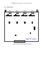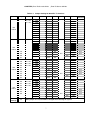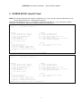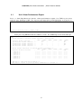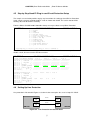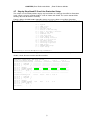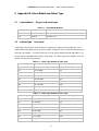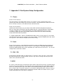
1
Quad E1/T1 Card For AM3440-A/B/C USER'S MANUAL LOOP TELECOMMUNICATION INTERNATIONAL, INC. 8F, NO. 8, HSIN ANN RD. SCIENCE-BASED INDUSTRIAL PARK HSINCHU, TAIWAN Tel: +886-3-578-7696 Fax: +886-3-578-7695 1 2010 Loop Telecommunication International, Inc. All rights reserved. 30 NOV 2010 Version 2 2 TABLE OF CONTENT 1. 2. 3. PRODUCT INTRODUCTION.................................................................................................................... 1 1.1 Description ................................................................................................................................... 1 1.2 Specification ................................................................................................................................. 1 1.3 Application Illustration .................................................................................................................. 2 INSTALLATION ......................................................................................................................................... 3 2.1 Site Selection ............................................................................................................................... 3 2.2 Mechanical Installation................................................................................................................. 3 2.2 LED Indication.............................................................................................................................. 5 2.3 Pin Definition ................................................................................................................................ 5 2.4 Jumper Setting ............................................................................................................................. 6 SYSETM SETUP: Quad E1 Card ............................................................................................................. 9 3.1 Unit 1-Hour Performance Report ............................................................................................... 10 3.2 Unit 24-Hour Performance Report ..............................................................................................11 3.3 Unit Line Availability ................................................................................................................... 12 3.4 Unit Configuration ...................................................................................................................... 12 3.5 Unit Status.................................................................................................................................. 13 3.6 Unit Alarm History ...................................................................................................................... 13 3.7 Unit Alarm Queue....................................................................................................................... 14 3.8 4. Unit Loopback Setup ......................................................................................................... 14 3.9 Unit System Setup ..................................................................................................................... 15 3.10 Unit Clear Performance Data..................................................................................................... 17 3.11 Unit Alarm Setup ........................................................................................................................ 17 3.12 Unit Clear Alarm Queue & History ............................................................................................. 18 3.13 Unit Upgrade Firmware.............................................................................................................. 18 3.14 Unit Load Default Configuration................................................................................................. 19 3.15 Unit Reset .................................................................................................................................. 19 SYSTEM SETUP: Quad T1 Card ........................................................................................................... 20 4.1 Unit 1-Hour Performance Report ............................................................................................... 21 4.2 Unit 24-Hour Performance Report ............................................................................................. 22 4.3 Unit Line Availability ................................................................................................................... 23 4.4 Unit Configuration ...................................................................................................................... 23 4.5 Unit Status.................................................................................................................................. 24 4.6 Unit Alarm History ...................................................................................................................... 24 4.7 Unit Alarm Queue....................................................................................................................... 25 4.8 Customer Information Setup ...................................................................................................... 25 4.9 Unit Loopback Setup ......................................................................................................... 26 4.10 Unit System Setup ..................................................................................................................... 26 4.11 Unit Clear Performance Data..................................................................................................... 28 4.12 Unit Alarm Setup ........................................................................................................................ 28 3 5 4.13 Unit Clear Alarm Queue & History ............................................................................................. 29 4.14 Unit Upgrade Firmware.............................................................................................................. 29 4.15 Unit Load Default Configuration................................................................................................. 30 4.16 Unit Reset .................................................................................................................................. 30 Appendix A – 1:1 Protection for Quad E1 Card ...................................................................................... 31 4.1 Introduction ................................................................................................................................ 31 4.2 Setting Up Circuit Protection...................................................................................................... 31 4.2.1 Connecting the Y-Box to the AM 3440 Shelf................................................................. 31 Figure 9- 1 Connection for AM3440 and Y-BOX with RJ48C connectors................................................. 32 4.3 Quad E1 card Location .............................................................................................................. 32 4.4 Setting up a VT-100 Monitor ...................................................................................................... 32 4.5 Step by Step Quad E1 Plug-in card Circuit Protection Setup .................................................... 33 4.6 Setting Up Line Protection ......................................................................................................... 33 4.7 6 7 Step by Step Quad E1 Card Line Protection Setup .......................................................... 34 Appendix B- Alarm Model and Alarm Type ............................................................................................. 35 5.1 ccAlarmModel: Plug-in card model type.................................................................................. 35 5.2 ccAlarmType: Unit alarm ......................................................................................................... 35 Appendix C: Port System Setup Configuration....................................................................................... 36 7.1 Frame......................................................................................................................................... 36 7.2 Code........................................................................................................................................... 36 7.3 RAI / YEL ................................................................................................................................... 36 7.4 CRC ........................................................................................................................................... 36 7.5 AIS ............................................................................................................................................. 37 7.6 SIGNALLING.............................................................................................................................. 37 7.7 CAS............................................................................................................................................ 37 7.8 Carrier Group Alarm ................................................................................................................... 37 7.9 OOS: Out of Service Signaling .................................................................................................. 38 7.10 Facility Data Link - In-Band Signaling ........................................................................................ 38 7.11 Facility Data Link........................................................................................................................ 38 7.12 INTF (Interface).......................................................................................................................... 38 7.13 LBO (Line Build-Out).................................................................................................................. 38 7.14 Idle Code.................................................................................................................................... 38 4 LIST OF FIGURES Figure 2-1 Quad E1 Card with RJ48C Connector ......................................................................... 3 Figure 2-2 Quad T1 Card with RJ48C Connector ......................................................................... 4 Figure 2-3 Quad E1 Card with BNC Connector ............................................................................ 4 Figure 4-1 Connection for AM3440 and Y-BOX with BNC connectors........................................ 32 Figure 4-2 Line Protection for Quad E1 Card .............................................................................. 33 LIST OF TABLES Table 2-1 LED Indication................................................................................................................ 5 Table 2-2 QE1/T1 Pin Definition .................................................................................................... 5 Table 2-3 Jumper Setting for Quad E1/ T1 Interface..................................................................... 7 Table 5-1 Alarm Model Number................................................................................................... 35 Table 5-2 Alarm Type Number for QE1 Card............................................................................... 35 Table 5-3 Alarm Type Number for QT1 Card............................................................................... 35 5 CHAPTER ¡Error! Estilo no definido. ¡Error! Estilo no definido. 1. PRODUCT INTRODUCTION 1.1 Description Loop Telecom’s QT1/QE1 plug-in cards are a series of 2 different plug-in cards designed for the Loop-AM3440 series. They allow each DS0 time slot in QT1 or QE1 interfaces to be interchanged and multiplexed onto a digital network. Continuous error checking, performance polling, and in-service diagnostics are provided through the main controller of the Loop-AM3440 series. In addition, an LED on the plug-in provides status indication. 1.2 Specification Network Line Interface (QT1) Line Rate 1.544 Mbps ± 32 ppm Framing D4/ESF Line Code AMI/B8ZS Connector RJ48C Input Signal DSX-1 0dB to –30dB w/ALBO Output Signal DSX-1 w/0, -7.5, -15 dB LBO Jitter AT&T TR 62411 Pulse Template AT&T TR 62411 Data Rate n * (64) Kbps (n=1-24) Surge Protection FCC Part 68 Sub Part D Network Line Interface (QE1) Line Rate 2.048 Mbps ± 50 ppm Framing ITU G.704 Line Code AMI/HDB3 Connector RJ48C or BNC Input Signal ITU G.703 Output Signal ITU G.703 Jitter ITU G.823 Electrical 75Ω coax/120Ω twisted pair Data Rate n * (64) Kbps (n = 1 - 32) 1 CHAPTER ¡Error! Estilo no definido. 1.3 ¡Error! Estilo no definido. Application Illustration All Other Cards Loop-AM 3440 QE1/QT1 WAN 2 CHAPTER ¡Error! Estilo no definido. 2. ¡Error! Estilo no definido. INSTALLATION 2.1 Site Selection The following list indicates a site selection guideline. Users need to follow this guideline to select a proper installation site. Location of the Rack should be part of the central office equipment layout design. Considerations should be given to entrance cable routing and -48 Vdc power. The installation site should have -48 Vdc power. An optional AC/DC power converter can be used. Use Only with Class 2 power source, -48 Vdc, 100 watts. 2.2 Mechanical Installation The Quad E1/T1 card is designed to be plugged into any of the available slots from 1 to 12 in the Loop-AM3440 devices. The 4E1 card supports RJ48C connector or BNC connector, and 4T1 card supports RJ48C connecotr only. The front panel is shown in the following figure. Figure 2-1 Quad E1 Card with RJ48C Connector 3 CHAPTER ¡Error! Estilo no definido. Figure 2-2 Figure 2-3 ¡Error! Estilo no definido. Quad T1 Card with RJ48C Connector Quad E1 Card with BNC Connector 4 CHAPTER ¡Error! Estilo no definido. 2.2 ¡Error! Estilo no definido. LED Indication The front of the Loop-AM 3440 has LEDs for operation and error indications. The indication can be in one or more colors. Note that when powering up and self test is in progress, the unit front panel LEDs are also used to indicate fault conditions. Table 2-1 LED Indication LED Color Off Green SYNC/ALM (One per port) 2.3 Flashing Green Red Flashing Red Flashing Green slowly Indication No signal or port not equipped Normal, 4E1/ T1 interface in sync In master mode (as protection function is enable) 4E1/ T1 interface loopback test in progress Alarm, 4E1/ T1 interface is unsync Receive RAI In slave mode (as protection function is enable) Pin Definition Table 2-2 Pin Number QE1/T1 Pin Definition Signal Signal Description 1 Receive Tip From T1/E1 Network 2 Receive Ring From T1/E1 Network 3 Unassigned 4 Transmit Tip To T1/E1 Network 5 Transmit Ring To T1/E1 Network 6 Unassigned 7 Chassis Ground 8 Chassis Ground 5 CHAPTER ¡Error! Estilo no definido. 2.4 ¡Error! Estilo no definido. Jumper Setting PORT 4 PORT 3 JP54 JP41 1 2 3 1 2 3 3 2 1 3 2 1 1 2 3 JP53 JP48 JP27 JP51 PORT 2 JP49 JP46 JP44 JP28 1 2 3 3 2 1 3 2 1 JP25 JP23 JP22 JP15 1 2 3 1 2 3 3 2 1 3 2 1 JP14 JP33 JP31 JP45 PORT 1 JP12 JP10 JP9 1 2 3 1 2 3 3 2 1 3 2 1 JP14 JP12 JP20 JP18 JP32 JP10 JP9 JP7 JP6 JP19 JP5 JP64 JP65 JP62 JP63 JP61 JP60 JP57 JP58 JP59 Quad E1/T1 Interface Figure 2- 1 Jumper Location for Quad E1/ T1 Interface 6 CHAPTER ¡Error! Estilo no definido. Table 2-3 For Port 4 ¡Error! Estilo no definido. Jumper Setting for Quad E1/ T1 Interface Jumper RJ BNC 9 2, 3 ON 1, 2 ON 10 2, 3 ON 1, 2 ON 12 2, 3 ON 1, 2 ON 14 2, 3 ON 1, 2 ON 15 120 Ω GND 75 Ω 100 Ω 5 ON 7 OFF ON OFF 22 2, 3 ON 1, 2 ON 23 2, 3 ON 1, 2 ON 25 2, 3 ON 1, 2 ON 27 2, 3 ON 1, 2 ON 28 ON ON 19 OFF ON 20 OFF ON 60 OFF OFF 61 OFF 35 2, 3 ON 1, 2 ON 36 2, 3 ON 1, 2 ON 38 2, 3 ON 1, 2 ON 40 2, 3 ON 1, 2 ON 41 ON ON ON 31 ON 32 OFF ON 33 OFF ON 62 OFF OFF 63 OFF 48 2, 3 ON 1, 2 ON 49 2, 3 ON 1, 2 ON 51 2, 3 ON 1, 2 ON 53 2, 3 ON 1, 2 ON ON ON ON 44 ON 45 OFF ON 46 OFF ON 64 For Bank Change ON ON 18 54 OFF OFF 59 For Port 1 Circuit Protection OFF ON 58 For Port 2 T1 ON 6 For Port 3 E1 OFF OFF 65 OFF 57 When jumper 57 is on, bank will be changed after rebooting the system. 7 ON ON CHAPTER ¡Error! Estilo no definido. 8 ¡Error! Estilo no definido. CHAPTER ¡Error! Estilo no definido. ¡Error! Estilo no definido. 3. SYSETM SETUP: Quad E1 Card NOTE: The terminal operations for Quad E1 and Quad T1 are same. Only the content information for "Unit System Setup" of Quad T1 is different from Quad E1. Under the Controller Menu, press “U” to choose a slot for Quad E1 port. The screen will show as below. Then press “P” to choose E1 port, press ENTER to get into the port menu. S L O T 1 1 Q ua d -E 1 PO R T 1 V e r si o n [ D I SP L AY ] 1 - > U ni t 2 - > U ni t A - > U ni t C - > U ni t I - > U ni t H - > U ni t Q - > U ni t = = = P or t Me nu = == 1 4 :48 : 3 0 0 9/ 3 0/ 2 00 3 : S W S 1.E 0 09 / 22 / 20 0 3 [ S ET U P ] L -> U n it Lo o pb a ck S et u p S - > U n it Sy s te m S e t up K - > U n it Cl e ar Pe r f or m anc e Da t a M -> U ni t A l ar m S e t up X -> U ni t C l ea r A l a rm Que u e & Hi s to r y D -> U ni t U p gr a de F ir m war e 1 - Ho u r P e rf. R ep o rt 2 4 -H o u r P erf . Re p or t L i ne A va i lab i l it y C o nf i g ur a tio n S t at u s A l ar m Hi s tor y A l ar m Qu e ue [ L O G] U - > C ho o se Ot h e r S lot P - > C ho o se E1 P or t F - > L og Of f [ S E TU P ],[ M I SC ] M e nu O - > L og On [ S ET U P] ,[ M I SC ] M e nu E - > R et u rn to C on t rol l e r M ai n M e nu Port : 02 [MISC] Y -> U ni t L o ad De f a ul t Co n f ig Z -> U ni t R e se t > > Pl e as e i n pu t E1 Po r t ( 1 -4 ) , t he n pr e ss E N TE R T his port menu is for Quad E1 Port 2. S L O T 1 1 Q ua d -E 1 PO R T 2 V e r si o n [ D I SP L AY ] 1 - > U ni t 2 - > U ni t A - > U ni t C - > U ni t I - > U ni t H - > U ni t Q - > U ni t = = = P or t Me nu = == 1 4 :48 : 4 0 0 9/ 3 0/ 2 00 3 : S W S 1.E 0 09 / 22 / 20 0 3 1 - Ho u r P e rf. R ep o rt 2 4 -H o u r P erf . Re p or t L i ne A va i lab i l it y C o nf i g ur a tio n S t at u s A l ar m Hi s tor y A l ar m Qu e ue [ L O G] U - > C ho o se Ot h e r S lot P - > C ho o se E1 P or t F - > L og Of f [ S E TU P ],[ M I SC ] M e nu O - > L og On [ S ET U P] ,[ M I SC ] M e nu E - > R et u rn to C on t rol l e r M ai n M e nu [ S ET U P ] L -> U n it Lo o pb a ck S et u p S - > U n it Sy s te m S e t up K - > U n it Cl e ar Pe r f or m anc e Da t a M -> U ni t A l ar m S e t up X -> U ni t C l ea r A l a rm Que u e & Hi s to r y D -> U ni t U p gr a de F ir m war e [MISC] Y -> U ni t L o ad De f a ul t Co n f ig Z -> U ni t R e se t > > S PA C E b ar to r ef r esh o r e nt e r a c o m ma n d = = = > 9 CHAPTER ¡Error! Estilo no definido. 3.1 ¡Error! Estilo no definido. Unit 1-Hour Performance Report Press “1” from Port Menu to view the 1-hour performance report. Use T AB k ey to select register type, USER or LINE. T he current selection will be highlighted by an asterisk (*). S L O T 1 1 Q ua d -E 1 PO R T 2 = = = P or t 1 - Ho u r P e rf. R ep o rt == = > > Se l ec t R e gi s t er Typ e ? * US E R 1 4: 48 : 5 0 0 9/ 3 0/ 2 00 3 LINE After pressing ENT ER from the above screen, the following screen will show up. S L O T 1 1 Q ua d -E 1 PO R T 2 = = = P or t 1 - Ho u r P e rf. R ep o rt == = 1 4: 49 : 0 2 0 9/ 3 0/ 2 00 3 USER - - Va l id Se c on d s i n Cu r r en t 1 5 -M i n I n te r val : 8 3 3 s ec o nd s (ES) ( U A S) ( BE S ) ( S E S) (DM) ( C SS ) C u r re n t 1 5- M i n I nte r v al : 0 8 33 0 0 0 140 1 s t N e ar e st 1 5- M in I n te r va l : 0 900 0 0 0 150 2 n d N e ar e st 1 5- M in I n te r va l : 0 900 0 0 0 151 3 r d N e ar e st 1 5- M in I n te r va l : 0 900 0 0 0 151 4 t h N e ar e st 1 5- M in I n te r va l : 0 0 0 0 0 0 - - Va l id 15 - Mi n In t erv a l s i n C ur r en t 24 - Hou r In t er v al : 2 0 (ES) ( U A S) ( BE S ) ( S E S) C u r re n t 2 4- H o ur Int e r va l : 0 1 80 0 0 0 0 0 9 / 29 / 20 0 3 : - -- - --- - -- - -- -- - 0 9 / 28 / 20 0 3 : - -- - --- - -- - -- -- - 0 9 / 27 / 20 0 3 : - -- - --- - -- - -- -- - 0 9 / 26 / 20 0 3 : - -- - --- - -- - -- -- - 0 9 / 25 / 20 0 3 : - -- - --- - -- - -- -- - 0 9 / 24 / 20 0 3 : - -- - --- - -- - -- -- - 0 9 / 23 / 20 0 3 : - -- - --- - -- - -- -- - - < < TA B k e y t o s h ow Sta t i st i cs Re p or t >> < < ES C k e y t o r e tu r n t o pr e vi o us me n u , S PAC E ba r t o r e fr e s h > > 10 (DM) 0 --- - --- - --- - --- - --- - --- - --- - - ( C SS ) 255 -- - --- - --- - --- - --- - --- - --- - -- CHAPTER ¡Error! Estilo no definido. 3.2 ¡Error! Estilo no definido. Unit 24-Hour Performance Report Press “2” from Port Menu to view the 24-hour performance report. Use T AB k ey to select register type, USER or LINE, press ENTER. Then m ove the cursor to select the desired param eter. T he current selection will be highlighted by an asterisk (*). S L O T 1 1 Q ua d -E 1 PO R T 2 = = = P or t 2 4 -H o u r P erf . Re p or t = = = > > Se l ec t R e gi s t er Typ e ? * US E R LINE > > Se l ec t P a ra m e te r ? * E S UAS BES SE S CSS DM AS 14 : 49 : 2 6 0 9/ 3 0/ 2 00 3 EFS BP V After pressing ENT ER from the above screen, the following screen will show up. S L O T 1 1 Q ua d -E 1 PO R T 2 = = = P or t 2 4 -H o u r P erf . Re p or t = = = 14 : 49 : 3 8 0 9/ 3 0/ 2 00 3 USER ES - - Va l id Se c on d s i n Cu r r en t 1 5 -M i n I n te r val : 8 6 9 s ec o nd s - - Va l id 15 - Mi n In t erv a l s i n C ur r en t 24 - Hou r In t er v al : 2 0 (ES) ( U A S) ( BE S ) ( S E S) (DM) ( C SS ) C u r re n t 1 5- M i n I nte r v al : 0 8 69 0 0 0 146 C u r re n t 2 4- H o ur Int e r va l : 0 1 80 0 0 0 0 0 255 - - US E R, 0 1 - 08 0 9 - 16 1 7 - 24 2 5 - 32 3 3 - 40 4 1 - 48 4 9 - 56 5 7 - 64 6 5 - 72 7 3 - 80 8 1 - 88 8 9 - 96 ES , L a s t 9 6 1 5 - Mi n I n te r va l : > 0 0 0 0 0 0 0 0 > 0 0 0 0 0 0 0 0 > 0 0 0 0 - - -- - -- - - - - -- - - - -- - > - -- - - - - --- - -- - - - -- - - - - -- - -- - - - - -- - - - -- - > - -- - - - - --- - -- - - - -- - - - - -- - -- - - - - -- - - - -- - > - -- - - - - --- - -- - - - -- - - - - -- - -- - - - - -- - - - -- - > - -- - - - - --- - -- - - - -- - - - - -- - -- - - - - -- - - - -- - > - -- - - - - --- - -- - - - -- - - - - -- - -- - - - - -- - - - -- - > - -- - - - - --- - -- - - - -- - - - - -- - -- - - - - -- - - - -- - > - -- - - - - --- - -- - - - -- - - - - -- - -- - - - - -- - - - -- - > - -- - - - - --- - -- - - - -- - - - - -- - -- - - - - -- - - - -- - > - -- - - - - --- - -- - - - -- - - - - -- - -- - - - - -- - - - -- - - < < TA B k e y t o s h ow Sta t i st i cs Re p or t >> < < ES C k e y t o r e tu r n t o pr e vi o us me n u , S PAC E ba r t o r e fr e s h > > 11 CHAPTER ¡Error! Estilo no definido. 3.3 ¡Error! Estilo no definido. Unit Line Availability Under Port Menu, press “A” to view the line availability as the following screen shows. S L O T 1 1 Q ua d -E 1 PO R T 2 = = = P or t L i n e A va il a b il i ty == = 1 4: 49 : 4 6 0 9/ 3 0/ 2 00 3 - - Li n e A va i la b i li t y d u r in g L a st 24 - H ou r : V a l id Se c on d s : 1 88 7 7 s ec o nd s A v a il a bl e S e c on d s : 0 s e co n ds U n a va i la b le S ec o nds : 18 8 77 se c on d s L i n e A va l ia b i li t y : 0 .0 % < < ES C k e y t o r e tu r n t o pr e vi o us me n u , S PAC E ba r t o r e fr e s h > > 3.4 Unit Configuration T o view the unit configuration, press “C” from Port Menu, then the screen will show as below. T here are four options are available for FDL item: OFF, SSM, FDL, and HDLC. S L O T 1 1 Q ua d -E 1 PO R T 2 F R A ME = CODE = CRC = RAI = AIS = CAS = S I G NA L LI N G= CGA = OOS = FDL = S a _ bi t = IDLE = P r o te c te d = M a s te r = INTF = = = = P or t S y s te m S e t up == = 1 4: 49 : 5 3 0 9/ 3 0/ 2 00 3 ON H DB 3 ON ON F R AME D OFF T RA NS N O RM B U SY OFF Sa4 D5 D IS AB L E * * ** 1 20 O h m < < ES C k e y t o r e tu r n t o pr e vi o us me n u , S PAC E ba r t o r e fr e s h > > Note: FDL can be enabled in a m axim um of 2 ports. 12 CHAPTER ¡Error! Estilo no definido. ¡Error! Estilo no definido. 3.5 Unit Status Press “I” from Port Menu, to show the screen of Unit Status as below. All of the following plug-in cards support remote link identification: DTU-6, DTU-10, HDSL, G. SHDSL-2, G. SHDSL-4, E1, QE1, and MiniQE1. S L O T 1 1 Q ua d -E 1 PO R T 2 - - LI N E - LOS : LOF : RCV AIS : RCV RAI : XMT AIS : XMT RAI : B P V E R RO R ES E RR O R Y ES L OF NO NO NO RAI C O U NT : 0 C OU N T : 0 = = = P or t St a tu s == = 1 4: 50 : 0 3 0 9/ 3 0/ 2 00 3 -- R E MO T E L IN K I D E NT I FIC A T IO N - T YP E : CPE S ER I A L_ N O : 2 62 2 4 - - TE S T - P A T TE R N T RA N S MI T TED : O F F N E A R- E ND LO O P BA C K : O FF < < ES C k e y t o r e tu r n t o pr e vi o us me n u , S PAC E ba r t o r e fr e s h > > 3.6 Unit Alarm History T o view the unit alarm history, press “H” from Port Menu. S L O T 1 1 Q ua d -E 1 PO R T 2 = = = P or t A l a rm Hi s t or y = = = L O C AL [ A L AR M -T Y PE ] [ TH R ESH O L D] [ CU R R- S T AT E ] [ C O UN T ] RAI D I S A BL E 0 AIS D I S A BL E 0 LOS D I S A BL E 0 LOF D I S A BL E 0 BPV 1 0E - 5 DI S A BL E 0 ES 1 D I S A BL E 0 UAS 1 D I S A BL E 0 CSS 1 D I S A BL E 0 14 : 50 : 1 1 0 9/ 3 0/ 2 00 3 [ A LA R M ] D I S AB LE D I S AB LE D I S AB LE D I S AB LE D I S AB L E D I S AB LE D I S AB LE D I S AB LE < < ES C k e y t o r e tu r n t o pr e vi o us me n u , S PAC E ba r t o r e fr e s h > > 13 CHAPTER ¡Error! Estilo no definido. 3.7 ¡Error! Estilo no definido. Unit Alarm Queue Under Port Menu, press “Q” to view the alarm queue as the following screen shows. S L O T 1 1 Q ua d -E 1 1 - - S lo t 1 1 : 2 - - S lo t 1 1 : 3 - - S lo t 1 1 : 4 - - S lo t 1 1 : 5 - - S lo t 1 1 : 6 - - S lo t 1 1 : PO R T 2 = = = U ni t A l a rm Q u e ue == = 1 4: 50 : 1 9 0 9/ 3 0/ 2 00 3 E 1 #1 ES r em o ve - -- - - -- - --- - - -- - -- - -1 1 :1 8 : 34 09/ 3 0 /2 0 03 E 1 #1 E S -- - -- - -- - -- - - -- - -- - - -- - -- - -1 1 :1 8 : 33 09/ 3 0 /2 0 03 E 1 #1 C S S r e mo v e- - -- - - -- - -- - - -- - -- - -1 0 :5 3 : 01 09/ 3 0 /2 0 03 E 1 #1 C S S -- - -- - -- - -- - - -- - -- - - -- - -- - -1 0 :5 2 : 59 09/ 3 0 /2 0 03 E 1 #1 U A S r e mo v e- - -- - - -- - -- - - -- - -- - -1 0 :5 2 : 59 09/ 3 0 /2 0 03 E 1 #1 U A S -- - -- - -- - -- - - -- - -- - - -- - -- - -1 0 :5 2 : 58 09/ 3 0 /2 0 03 < < ES C k e y r et u r n t o p r e vi o us me n u o r S P ACE b ar to re f re s h > > 3.8 Unit Loopback Setup Under Port Menu, press “L” to do Loopback Test, then the screen will show as below. Use arrow k eys to m ove the cursor, press ENT ER key to select items. S L O T 1 1 Q ua d -E 1 PO R T 2 = = = P or t L o o pb a ck T es t = = = A R R OW KE Y S : C U R SO R MO V E , EN T ER KE Y : I TEM S EL E CT - N EA R -E N D L OO P B AC K : * OF F LO C AL PLB LLB - S EN D L O OP B AC K AC T IVA T E C O DE TO FA R - EN D : * P A YL O AD L I NE - S EN D L O OP B AC K DE A CTI V A TE CO D E T O F A R- E ND: * P A YL O AD L I NE - S EN D T E ST PA T T ER N : *OFF P R B S- F UL L - S TA T US : < < Pr e ss ES C k e y t o re t u rn to pr e vi o u s m enu > > 14 14 : 50 : 3 2 0 9/ 3 0/ 2 00 3 CHAPTER ¡Error! Estilo no definido. 3.9 ¡Error! Estilo no definido. Unit System Setup T o set up unit s ystem , press “S” from Port Menu, then the following screen will show up. Use arrow k eys to m ove the cursor, T AB key to roll up options. NOT E: If "Protected" is set as DISABLE, then "Master" option will show 4 asterisks (****), which m eans this option is not allowed to set up. For Quad E1: S L O T 1 1 Q ua d -E 1 PO R T 2 = = = P or t S y s te m S e t up == = A R R OW KE Y S: CU R S OR MOV E , T A B: RO L L O P TI O NS F R A ME = CODE = CRC = RAI = AIS = CAS = S I G NA L LI N G= CGA = OOS = FDL = S a _ bi t = IDLE = P r o te c te d = M a s te r = INTF = 1 4: 50 : 3 9 0 9/ 3 0/ 2 00 3 ON H DB 3 ON ON F R AME D OFF T RA NS N O RM B U SY OFF Sa4 D5 D IS AB L E * * ** 1 20 O h m < < Pr e ss ES C k e y t o re t u rn to pr e vi o u s m enu > > Note: For detailed description for each function, see Appendix C: System Port Setup Configuration Configuration Option Default Frame ON, OFF ON CODE HDB3, AMI HDB3 CRC (Cyclic Redundanc y Check) ON, OFF ON RAI (Remote Alarm Indication) ON, OFF ON AIS (Alarm Indication Signal) FRAMED, FRAMED UNFRAMED, OFF CAS (Channel Associated Signaling) ON, OFF OFF SIGNALLING TRANS, CD=01 TRANS CGA (Carrier Group Alarm) NORM NORM OOS (Out of Service) BUSY, IDLE, AIS BUSY FDL (Facility Data Lock) OFF, HDLC, SSM, OFF FDL Sa-bit Sa4, Sa5, Sa6, Sa7, Sa4 Sa8, Sa4+Sa5 IDLE 00-FF D5 15 CHAPTER ¡Error! Estilo no definido. ¡Error! Estilo no definido. For Quad T1: S L O T 1 Q u ad - T1 P OR T 1 = = = P o rt Sy s t em S e t up == = A R R OW KE Y S: CU R S OR MOV E , T A B: RO L L O P TI O NS F R A ME = CODE = YEL = AIS = CAS = S I G NA L LI N G= CGA = OOS = I N B AN D = IDLE = INTF = LBO = FDL = P r o te c te d = M a s te r = ES F B 8Z S ON F R AME D OFF T RA NS N O RM B U SY OFF FF L ON G H A UL 0 dB FDL D IS AB L E * * ** < < Pr e ss ES C k e y t o re t u rn to pr e vi o u s m enu > > 16 1 1: 08 : 4 5 0 8/ 3 0/ 2 00 4 CHAPTER ¡Error! Estilo no definido. 3.10 ¡Error! Estilo no definido. Unit Clear Performance Data Press “K” from Port Menu to clear performance data, the screen will show as below. Press “Y” or “N” to confirm the commend. S L O T 1 1 Q ua d -E 1 PO R T 2 V e r si o n [ D I SP L AY ] 1 - > U ni t 2 - > U ni t A - > U ni t C - > U ni t I - > U ni t H - > U ni t Q - > U ni t = = = P or t Me nu = == 1 4 :50 : 4 5 0 9/ 3 0/ 2 00 3 : S W S 1.E 0 09 / 22 / 20 0 3 1 - Ho u r P e rf. R ep o rt 2 4 -H o u r P erf . Re p or t L i ne A va i lab i l it y C o nf i g ur a tio n S t at u s A l ar m Hi s tor y A l ar m Qu e ue [ L O G] U - > C ho o se Ot h e r S lot P - > C ho o se E1 P or t F - > L og Of f [ S E TU P ],[ M I SC ] M e nu O - > L og On [ S ET U P] ,[ M I SC ] M e nu E - > R et u rn to C on t rol l e r M ai n M e nu [ S ET U P ] L -> U n it Lo o pb a ck S et u p S - > U n it Sy s te m S e t up K - > U n it Cl e ar Pe r f or m anc e Da t a M -> U ni t A l ar m S e t up X -> U ni t C l ea r A l a rm Que u e & Hi s to r y D -> U ni t U p gr a de F ir m war e [MISC] Y -> U ni t L o ad De f a ul t Co n f ig Z -> U ni t R e se t = = > C l ea r p e rf o r ma n ce d a ta - a re yo u su r e [ Y / N] ? 3.11 Unit Alarm Setup T o do alarm setup, press “M” from Port Menu, then the following screen will show up. S L O T 1 1 Q ua d -E 1 PO R T 2 = = = P or t A l a rm S e t up == = A R R OW KE Y S: CU R S OR MOV E , T A B: RO L L O P TI O NS [ T Y PE ] RAI AIS LOS LOF BPV ES UAS CSS [T H RE S H OL D ] [ A LA R M] D I S AB L E D I S AB L E D I S AB L E D I S AB L E 10 E - 5 D I S AB L E 001 D I S AB L E 0 01 D I S AB L E 0 01 D I S AB L E < < Pr e ss ES C k e y t o re t u rn to pr e vi o u s m enu > > 17 1 4: 50 : 5 9 0 9/ 3 0/ 2 00 3 CHAPTER ¡Error! Estilo no definido. 3.12 ¡Error! Estilo no definido. Unit Clear Alarm Queue & History Under Port Menu, press “X” to clear alarm queue and history, then press “Y” or ”N” to confirm it. S L O T 1 1 Q ua d -E 1 PO R T 2 V e r si o n [ D I SP L AY ] 1 - > U ni t 2 - > U ni t A - > U ni t C - > U ni t I - > U ni t H - > U ni t Q - > U ni t = = = P or t Me nu = == 1 4 :51 : 0 5 0 9/ 3 0/ 2 00 3 : S W S 1.E 0 09 / 22 / 20 0 3 1 - Ho u r P e rf. R ep o rt 2 4 -H o u r P erf . Re p or t L i ne A va i lab i l it y C o nf i g ur a tio n S t at u s A l ar m Hi s tor y A l ar m Qu e ue [ S ET U P ] L -> U n it Lo o pb a ck S et u p S - > U n it Sy s te m S e t up K - > U n it Cl e ar Pe r f or m anc e Da t a M -> U ni t A l ar m S e t up X -> U ni t C l ea r A l a rm Que u e & Hi s to r y D -> U ni t U p gr a de F ir m war e [ L O G] U - > C ho o se Ot h e r S lot P - > C ho o se E1 P or t F - > L og Of f [ S E TU P ],[ M I SC ] M e nu O - > L og On [ S ET U P] ,[ M I SC ] M e nu E - > R et u rn to C on t rol l e r M ai n M e nu [MISC] Y -> U ni t L o ad De f a ul t Co n f ig Z -> U ni t R e se t > > Cl e ar al a rm q ue u e o f SL O T 1 1 - a r e y o u s u r e ? [ Y /N ] 3.13 Unit Upgrade Firmware Press “D” to download firm ware, then the screen will show as below. Use arrow k eys to move the cursor and SPACE k ey to edit. L O O P A M3 4 40 - A = = = D o wn l oa d Fi rm w a re == = 1 4: 51 : 2 1 0 9/ 3 0/ 2 00 3 A R R OW KE Y S: CU R S OR MOV E , P l ea s e I np u t : n nn. n n n. n nn . nn n , B A CK S PAC E to ed i t B a n k 1 F i rm w ar e Ve r . : B a n k 2 F i rm w ar e Ve r . : W o r ki n g F ir m wa r e B a nk: T F T P S er v er IP : F i r mw a re Fi l e N a me : S 1. E 0 0 9/ 2 2/ 2 0 03 S 1. E 0 0 9/ 2 2/ 2 0 03 1 0 00 . 00 0 .0 0 0. 0 0 0 ( B a d) ( B a d) < < Pr e ss ES C k e y t o re t u rn to pr e vi o u s m enu > > 18 CHAPTER ¡Error! Estilo no definido. 3.14 ¡Error! Estilo no definido. Unit Load Default Configuration Press “Y” to return to default, then confirm it by pressing “Y” or “N”. S L O T 1 1 Q ua d -E 1 PO R T 2 V e r si o n [ D I SP L AY ] 1 - > U ni t 2 - > U ni t A - > U ni t C - > U ni t I - > U ni t H - > U ni t Q - > U ni t = = = P or t Me nu = == 1 4 :51 : 2 9 0 9/ 3 0/ 2 00 3 : S W S 1.E 0 09 / 22 / 20 0 3 [ S ET U P ] L -> U n it Lo o pb a ck S et u p S - > U n it Sy s te m S e t up K - > U n it Cl e ar Pe r f or m anc e Da t a M -> U ni t A l ar m S e t up X -> U ni t C l ea r A l a rm Que u e & Hi s to r y D -> U ni t U p gr a de F ir m war e 1 - Ho u r P e rf. R ep o rt 2 4 -H o u r P erf . Re p or t L i ne A va i lab i l it y C o nf i g ur a tio n S t at u s A l ar m Hi s tor y A l ar m Qu e ue [ L O G] U - > C ho o se Ot h e r S lot P - > C ho o se E1 P or t F - > L og Of f [ S E TU P ],[ M I SC ] M e nu O - > L og On [ S ET U P] ,[ M I SC ] M e nu E - > R et u rn to C on t rol l e r M ai n M e nu [MISC] Y -> U ni t L o ad De f a ul t Co n f ig Z -> U ni t R e se t > > Re t ur n t o d e f au l t - a re yo u s u re ? [ Y /N] Note: W hen you load the default configuration, the current daughter card m ap will not be cleared. 3.15 Unit Reset Under Port Menu, press “Z” to reset unit. Press “Y” or “N” to confirm it. S L O T 1 1 Q ua d -E 1 PO R T 2 V e r si o n [ D I SP L AY ] 1 - > U ni t 2 - > U ni t A - > U ni t C - > U ni t I - > U ni t H - > U ni t Q - > U ni t = = = P or t Me nu = == 1 4 :51 : 2 9 0 9/ 3 0/ 2 00 3 : S W S 1.E 0 09 / 22 / 20 0 3 1 - Ho u r P e rf. R ep o rt 2 4 -H o u r P erf . Re p or t L i ne A va i lab i l it y C o nf i g ur a tio n S t at u s A l ar m Hi s tor y A l ar m Qu e ue [ L O G] U - > C ho o se Ot h e r S lot P - > C ho o se E1 P or t F - > L og Of f [ S E TU P ],[ M I SC ] M e nu O - > L og On [ S ET U P] ,[ M I SC ] M e nu E - > R et u rn to C on t rol l e r M ai n M e nu [ S ET U P ] L -> U n it Lo o pb a ck S et u p S - > U n it Sy s te m S e t up K - > U n it Cl e ar Pe r f or m anc e Da t a M -> U ni t A l ar m S e t up X -> U ni t C l ea r A l a rm Que u e & Hi s to r y D -> U ni t U p gr a de F ir m war e [MISC] Y -> U ni t L o ad De f a ul t Co n f ig Z -> U ni t R e se t R e s et - a re yo u su r e ? [ Y/ N ] 19 CHAPTER ¡Error! Estilo no definido. ¡Error! Estilo no definido. 4. SYSTEM SETUP: Quad T1 Card Under the Controller Menu, press “U” to choose a slot for Quad T1 card. The screen will show as below. S L O T 1 Q u ad - T1 P OR T 1 V e r si o n = = = P o r t M enu = == 1 5 :39 : 5 0 1 1/ 1 7/ 2 01 0 : S W V 3.0 3 . 01 10 / 29 / 20 1 0 [ D I SP L AY ] 1 - > U ni t 1 - Ho u r P e rf. R ep o rt 2 - > U ni t 2 4 -H o u r P erf . Re p or t A - > U ni t L i ne A va i lab i l it y C - > U ni t C o nf i g ur a tio n I - > U ni t S t at u s H - > U ni t A l ar m Hi s tor y Q - > U ni t A l ar m Qu e ue V - > C us t om e r I n fo r mat i o n D is p la y [ L O G] U - > C ho o se Ot h e r S lot P - > C ho o se E1 / T 1 P ort F - > L og Of f [ S E TU P ],[ M I SC ] M e nu O - > L og On [ S ET U P] ,[ M I SC ] M e nu E - > R et u rn to C on t rol l e r M ai n M e nu [ S ET U P ] L -> U n it Lo o pb a ck S et u p S - > U n it Sy s te m S e t up K - > U n it Cl e ar Pe r f or m anc e Da t a M -> U ni t A l ar m S e t up X -> U ni t C l ea r A l a rm Que u e & Hi s to r y D -> U ni t U p gr a de F ir m war e T -> C us t om e r I nf o r ma t ion S et u p [MISC] Y -> U ni t L o ad De f a ul t Co n f ig Z -> U ni t R e se t > > S PA C E b ar to r ef r esh o r e nt e r a c o m ma n d = = = > Then press “P” to choose an T1 port, a prompt will show at the bottom of the screen as below. Press ENTER to get into the port menu. Port : 01 > > P l ea s e i np u t P o rt N u mb e r ( 1~ 4 ), t he n pr e s s E NT E R . T his port menu is for Quad T 1 Port 1. S L O T 1 Q u ad - T1 P OR T 1 V e r si o n = = = P o r t M enu = == 1 5 :42 : 4 7 1 1/ 1 7/ 2 01 0 : S W V 3.0 3 . 01 10 / 29 / 20 1 0 [ D I SP L AY ] 1 - > U ni t 1 - Ho u r P e rf. R ep o rt 2 - > U ni t 2 4 -H o u r P erf . Re p or t A - > U ni t L i ne A va i lab i l it y C - > U ni t C o nf i g ur a tio n I - > U ni t S t at u s H - > U ni t A l ar m Hi s tor y Q - > U ni t A l ar m Qu e ue V - > C us t om e r I n fo r mat i o n D is p la y [ L O G] U - > C ho o se Ot h e r S lot P - > C ho o se E1 / T 1 P ort F - > L og Of f [ S E TU P ],[ M I SC ] M e nu O - > L og On [ S ET U P] ,[ M I SC ] M e nu E - > R et u rn to C on t rol l e r M ai n M e nu [ S ET U P ] L -> U n it Lo o pb a ck S et u p S - > U n it Sy s te m S e t up K - > U n it Cl e ar Pe r f or m anc e Da t a M -> U ni t A l ar m S e t up X -> U ni t C l ea r A l a rm Que u e & Hi s to r y D -> U ni t U p gr a de F ir m war e T -> C us t om e r I nf o r ma t ion S et u p [MISC] Y -> U ni t L o ad De f a ul t Co n f ig Z -> U ni t R e se t > > S PA C E b ar to r ef r esh o r e nt e r a c o m ma n d = = = > 20 CHAPTER ¡Error! Estilo no definido. ¡Error! Estilo no definido. 4.1 Unit 1-Hour Performance Report Press “1” from Port Menu to view the 1-hour performance report. Use T AB k ey to select register type, USER or LINE. T he current selection will be highlighted by an asterisk (*). S L O T 1 Q u ad - T1 P OR T 1 = = = P or t 1 - Ho u r P e rf. R ep o rt == = > > Se l ec t R e gi s t er Typ e ? * US E R 1 5: 44 : 1 8 1 1/ 1 7/ 2 01 0 LINE After pressing ENT ER from the above screen, the following screen will show up. Sam ple screen for USER: S L O T 1 Q u ad - T1 P OR T 1 = = = P or t 1 - Ho u r P e rf. R ep o rt == = 1 5: 44 : 5 3 1 1/ 1 7/ 2 01 0 USER - - Va l id Se c on d s i n Cu r r en t 1 5 -M i n I n te r val : 1 0 51 se c on d s (ES) ( U A S) ( BE S ) ( S E S) ( C S S) ( LO F C) C u r re n t 1 5- M i n I nte r v al : 1 0 46 0 543 50 3 66 0 1 s t N e ar e st 1 5- M in I n te r va l : 96 1 0 873 88 19 6 0 2 n d N e ar e st 1 5- M in I n te r va l : 34 2 6 68 265 77 32 0 3 r d N e ar e st 1 5- M in I n te r va l : 9 78 2 7 2 1 4 t h N e ar e st 1 5- M in I n te r va l : -- - - - -- - -- - -- -- - --- - -- - -- - Va l id 15 - Mi n In t erv a l s i n C ur r en t 24 - Hou r In t er v al : 3 (ES) ( U A S) ( BE S ) ( S E S) ( C S S) ( LO F C) C u r re n t 2 4- H o ur Int e r va l : 1 31 2 7 46 1 1 40 1 72 2 30 1 < < TA B k e y t o s h ow Sta t i st i cs Re p or t >> < < ES C k e y t o r e tu r n t o pr e vi o us me n u , S PAC E ba r t o r e fr e s h > > Sample screen for LINE: SLOT 1 Quad-T1 PORT 1 === Port 1-Hour Perf. Report === LINE -- Valid Seconds in Current 15-Min Interval : 21 seconds (ES) (UAS) (BES) (SES) (CSS) (LOFC) Current 15-Min Interval : 21 0 8 13 0 0 1st Nearest 15-Min Interval : 1054 0 545 509 66 0 2nd Nearest 15-Min Interval : 961 0 873 88 196 0 3rd Nearest 15-Min Interval : 342 668 265 77 32 0 4th Nearest 15-Min Interval : 9 78 2 7 2 1 -- Valid 15-Min Intervals in Current 24-Hour Interval: 4 (ES) (UAS) (BES) (SES) (CSS) (LOFC) Current 24-Hour Interval : < < TA B k e y t o s h ow Sta t i st i cs Re p or t >> < < E SC k ey t o r etu rn t o p r eviou s m enu, S PACE b a r t o r ef r es h >> 21 15:45:18 11/17/2010 CHAPTER ¡Error! Estilo no definido. ¡Error! Estilo no definido. 4.2 Unit 24-Hour Performance Report Press “2” from Port Menu to view the 24-hour performance report. Use T AB k ey to select register type, USER or LINE, press ENTER. Then m ove the cursor to select the desired param eter. T he current selection will be highlighted by an asterisk (*). S L O T 1 Q u ad - T1 P OR T 1 = = = P or t 2 4 -H o u r P erf . Re p or t = = = > > Se l ec t R e gi s t er Typ e ? * US E R LINE > > Se l ec t P a ra m e te r ? * E S UAS BES SE S CSS LO F C AS 15 : 48 : 1 2 1 1/ 1 7/ 2 01 0 E FS BP V E SF After pressing ENT ER from the above screen, the following screen will show up. S L O T 1 1 Q ua d -E 1 PO R T 2 = = = P or t 2 4 -H o u r P erf . Re p or t = = = 14 : 49 : 3 8 0 9/ 3 0/ 2 00 3 USER ES - - Va l id Se c on d s i n Cu r r en t 1 5 -M i n I n te r val : 8 6 9 s ec o nd s - - Va l id 15 - Mi n In t erv a l s i n C ur r en t 24 - Hou r In t er v al : 2 0 (ES) ( U A S) ( BE S ) ( S E S) (DM) ( C SS ) C u r re n t 1 5- M i n I nte r v al : 0 8 69 0 0 0 146 C u r re n t 2 4- H o ur Int e r va l : 0 1 80 0 0 0 0 0 255 - - US E R, 0 1 - 08 0 9 - 16 1 7 - 24 2 5 - 32 3 3 - 40 4 1 - 48 4 9 - 56 5 7 - 64 6 5 - 72 7 3 - 80 8 1 - 88 8 9 - 96 ES , L a s t 9 6 1 5 - Mi n I n te r va l : > 0 0 0 0 0 0 0 0 > 0 0 0 0 0 0 0 0 > 0 0 0 0 - - -- - -- - - - - -- - - - -- - > - -- - - - - --- - -- - - - -- - - - - -- - -- - - - - -- - - - -- - > - -- - - - - --- - -- - - - -- - - - - -- - -- - - - - -- - - - -- - > - -- - - - - --- - -- - - - -- - - - - -- - -- - - - - -- - - - -- - > - -- - - - - --- - -- - - - -- - - - - -- - -- - - - - -- - - - -- - > - -- - - - - --- - -- - - - -- - - - - -- - -- - - - - -- - - - -- - > - -- - - - - --- - -- - - - -- - - - - -- - -- - - - - -- - - - -- - > - -- - - - - --- - -- - - - -- - - - - -- - -- - - - - -- - - - -- - > - -- - - - - --- - -- - - - -- - - - - -- - -- - - - - -- - - - -- - > - -- - - - - --- - -- - - - -- - - - - -- - -- - - - - -- - - - -- - - < < TA B k e y t o s h ow Sta t i st i cs Re p or t >> < < ES C k e y t o r e tu r n t o pr e vi o us me n u , S PAC E ba r t o r e fr e s h > > 22 CHAPTER ¡Error! Estilo no definido. ¡Error! Estilo no definido. 4.3 Unit Line Availability Under Port Menu, press “A” to view the line availability as the following screen shows. L O T 1 Qu a d- T 1 P O RT 1 = = = P o rt Li n e A v ai la b i li t y = == 1 5 :4 8: 5 1 1 1 /1 7 /2 0 10 - - Li n e A va i la b i li t y d u r in g L a st 24 - H ou r : V a l id Se c on d s : 3 87 6 s e co n ds A v a il a bl e S e c on d s : 3 13 0 s e co n ds U n a va i la b le S ec o nds : 74 6 s e co n ds L i n e A va i la b i li t y : 8 0. 7 5 % < < ES C k e y t o r e tu r n t o pr e vi o us me n u , S PAC E ba r t o r e fr e s h > > 4.4 Unit Configuration T o view the unit configuration, press “C” from Port Menu, then the screen will show as below. T here are four options are available for FDL item: OFF, SSM, FDL, and HDLC. S L O T 1 Q u ad - T1 P OR T 1 F R A ME = CODE = YEL = AIS = CAS = S I G NA L LI N G= CGA = OOS = I N B AN D = IDLE = INTF = LBO = FDL = P r o te c te d = M a s te r = = = = P o rt Sy s t em S e t up == = 1 5: 49 : 1 2 1 1/ 1 7/ 2 01 0 ES F B 8Z S ON F R AME D OFF T RA NS N O RM B U SY OFF FF L ON G H A UL 0 dB OFF D IS AB L E * * ** < < ES C k e y t o r e tu r n t o pr e vi o us me n u , S PAC E ba r t o r e fr e s h > > Note: FDL can be enabled in a m axim um of 2 ports. 23 CHAPTER ¡Error! Estilo no definido. ¡Error! Estilo no definido. 4.5 Unit Status Press “I” from Port Menu, to show the screen of Unit Status as below. S L O T 1 Q u ad - T1 P OR T 1 - - LI N E - LOS : LOF : RCV AIS : RCV YEL : XMT AIS : XMT YEL : B P V E R RO R ES E RR O R = = = P o rt S ta tu s == = 1 5: 49 : 3 1 1 1/ 1 7/ 2 01 0 NO NO NO NO NO NO C O U NT : 6 5 5 35 C OU N T : 3 2 3 - - TE S T - P A T TE R N T RA N S MI T TED : O F F N E A R- E ND LO O P BA C K : O FF < < ES C k e y t o r e tu r n t o pr e vi o us me n u , S PAC E ba r t o r e fr e s h > > 4.6 Unit Alarm History T o view the unit alarm history, press “H” from Port Menu. S L O T 1 Q u ad - T1 P OR T 1 = = = P o rt Al a r m Hi s t or y = = = L O C AL [ A L AR M -T Y PE ] [ TH R ESH O L D] [ CU R R- S T AT E ] [ C O UN T ] YEL D I S A BL E 0 AIS D I S A BL E 0 LOS D I S A BL E 0 LOF D I S A BL E 0 BPV 1 0E - 5 DI S A BL E 0 ES 1 D I S A BL E 0 UAS 1 D I S A BL E 0 CSS 1 D I S A BL E 0 15 : 50 : 0 5 1 1/ 1 7/ 2 01 0 [ A LA R M ] D I S AB LE D I S AB LE D I S AB LE D I S AB LE D I S AB L E D I S AB LE D I S AB LE D I S AB LE < < ES C k e y t o r e tu r n t o pr e vi o us me n u , S PAC E ba r t o r e fr e s h > > 24 CHAPTER ¡Error! Estilo no definido. ¡Error! Estilo no definido. 4.7 Unit Alarm Queue Under Port Menu, press “Q” to view the alarm queue as the following screen shows. SLOT 1 1 -2 -3 -4 -5 -6 -- Q u ad - T1 P OR T 1 S lo t 0 1 : T 1 #1 S lo t 0 1 : T 1 #1 S lo t 0 1 : T 1 #1 S lo t 0 1 : T 1 #1 S lo t 0 1 : T 1 #1 S lo t 0 1 : T 1 #1 = = = U n it A la r m Q u e ue == = 1 5: 50 : 0 5 1 1/ 1 7/ 2 01 0 ES r em o ve - -- - - -- - --- - - -- - -- - -1 1 :1 8 : 34 09/ 3 0 /2 0 03 E S -- - -- - -- - -- - - -- - -- - - -- - -- - -1 1 :1 8 : 33 09/ 3 0 /2 0 03 C S S r e mo v e- - -- - - -- - -- - - -- - -- - -1 0 :5 3 : 01 09/ 3 0 /2 0 03 C S S -- - -- - -- - -- - - -- - -- - - -- - -- - -1 0 :5 2 : 59 09/ 3 0 /2 0 03 U A S r e mo v e- - -- - - -- - -- - - -- - -- - -1 0 :5 2 : 59 09/ 3 0 /2 0 03 U A S -- - -- - -- - -- - - -- - -- - - -- - -- - -1 0 :5 2 : 58 09/ 3 0 /2 0 03 < < ES C k e y r et u r n t o p r e vi o us me n u o r S P ACE b ar to re f re s h > > 4.8 Customer Information Setup Under Port Menu, press “V’ to view the customer information that relates to each port. S L O T 1 Q u ad - T1 P OR T 1 = = = C us t om e r I n for m a ti o n = == 1 5 :52 : 5 1 1 1/ 1 7/ 2 01 0 P1: P2: P3: P4: < < ES C k e y t o r e tu r n t o pr e vi o us me n u , S PAC E ba r t o r e fr e s h > > 25 CHAPTER ¡Error! Estilo no definido. ¡Error! Estilo no definido. 4.9 Unit Loopback Setup Under Port Menu, press “L” to do Loopback Test, then the screen will show as below. Use arrow k eys to m ove the cursor, press ENT ER key to select items. S L O T 1 Q u ad - T1 P OR T 1 = = = P o rt Lo o p ba ck T es t = = = A R R OW KE Y S : C U R SO R MO V E , EN T ER KE Y : I TEM S EL E CT - N EA R -E N D L OO P B AC K : * OF F LO C AL PLB 16 : 46 : 3 5 1 1/ 1 7/ 2 01 0 LLB - S EN D L O OP B AC K AC T IVA T E C O DE TO FA R - EN D : * I N -B A ND A T &T - P AN S I- P AN S I -L - S EN D L O OP B AC K DE A CTI V A TE CO D E T O F A R- E ND: * I N -B A ND A T &T - P AN S I- P AN S I -L - S EN D T E ST PA T T ER N : *OFF Q R S S- F UL L - S TA T US : < < Pr e ss ES C k e y t o re t u rn to pr e vi o u s m enu > > 4.10 Unit System Setup T o set up unit s ystem , press “S” from Port Menu, then the following screen will show up. Use arrow k eys to m ove the cursor, T AB key to roll up options. NOT E: If "Protected" is set as DISABLE, then "Master" option will show 4 asterisks (****), which m eans this option is not allowed to set up. S L O T 1 Q u ad - T1 P OR T 1 = = = P o rt Sy s t em S e t up == = A R R OW KE Y S: CU R S OR MOV E , T A B: RO L L O P TI O NS F R A ME = CODE = YEL = AIS = CAS = S I G NA L LI N G= CGA = OOS = I N B AN D = IDLE = INTF = LBO = FDL = P r o te c te d = M a s te r = ES F B 8Z S ON F R AME D OFF T RA NS N O RM B U SY OFF FF L ON G H A UL 0 dB OFF D IS AB L E * * ** < < Pr e ss ES C k e y t o re t u rn to pr e vi o u s m enu > > 26 1 6: 46 : 5 7 1 1/ 1 7/ 2 01 0 CHAPTER ¡Error! Estilo no definido. ¡Error! Estilo no definido. Note: For detailed description for each function, see Appendix C: System Port Setup Configuration Configuration Option Default Frame ESF, ESF&T 1,403, ESF None, D4 CODE B8ZS, AMI HDB3 YEL ON, OFF ON AIS (Alarm Indication Signal) FRAMED, FRAMED UNFRAMED, OFF CAS (Channel Associated Signaling) ON, OFF OFF SIGNALLING TRANS TRANS CGA (Carrier Group Alarm) NORM NORM OOS (Out of Service) BUSY, IDLE, AIS BUSY Inband ON, OFF OFF Idle 00-FF FF INT F LONG HAUL LONG HAUL SHORT HAUL LBO 0 db, -7.5db, -15db 0 db FDL (Facility Data Lock) OFF, FDL OFF 27 CHAPTER ¡Error! Estilo no definido. 4.11 ¡Error! Estilo no definido. Unit Clear Performance Data Press “K” from Port Menu to clear performance data, the screen will show as below. Press “Y” or “N” to confirm the commend. S L O T 1 Q u ad - T1 P OR T 1 V e r si o n = = = P o rt M en u == = 1 4 :5 0 :45 0 9/ 3 0/ 2 00 3 : S W S 1.E 0 09 / 22 / 20 0 3 [ D I SP L AY ] 1 - > U ni t 2 - > U ni t A - > U ni t C - > U ni t I - > U ni t H - > U ni t Q - > U ni t 1 - Ho u r P e rf. R ep o rt 2 4 -H o u r P erf . Re p or t L i ne A va i lab i l it y C o nf i g ur a tio n S t at u s A l ar m Hi s tor y A l ar m Qu e ue [ L O G] U - > C ho o se Ot h e r S lot P - > C ho o se E1 P or t F - > L og Of f [ S E TU P ],[ M I SC ] M e nu O - > L og On [ S ET U P] ,[ M I SC ] M e nu E - > R et u rn to C on t rol l e r M ai n M e nu [ S ET U P ] L -> U n it Lo o pb a ck S et u p S - > U n it Sy s te m S e t up K - > U n it Cl e ar Pe r f or m anc e Da t a M -> U ni t A l ar m S e t up X -> U ni t C l ea r A l a rm Que u e & Hi s to r y D -> U ni t U p gr a de F ir m war e [MISC] Y -> U ni t L o ad De f a ul t Co n f ig Z -> U ni t R e se t = = > C l ea r p e rf o r ma n ce d a ta - a re yo u su r e [ Y / N] ? 4.12 Unit Alarm Setup T o do alarm setup, press “M” from Port Menu, then the following screen will show up. S L O T 1 Q u ad - T1 P OR T 1 = = = P o rt Al a r m Se t u p = == A R R OW KE Y S: CU R S OR MOV E , T A B: RO L L O P TI O NS [ T Y PE ] RAI AIS LOS LOF BPV ES UAS CSS [T H RE S H OL D ] [ A LA R M] D I S AB L E D I S AB L E D I S AB L E D I S AB L E 10 E - 5 D I S AB L E 001 D I S AB L E 0 01 D I S AB L E 0 01 D I S AB L E < < Pr e ss ES C k e y t o re t u rn to pr e vi o u s m enu > > 28 1 4 :5 0: 5 9 0 9 /3 0 /2 0 03 CHAPTER ¡Error! Estilo no definido. 4.13 ¡Error! Estilo no definido. Unit Clear Alarm Queue & History Under Port Menu, press “X” to clear alarm queue and history, then press “Y” or ”N” to confirm it. S L O T 1 1 Q ua d -E 1 PO R T 2 V e r si o n = = = P or t Me nu = == 1 4 :51 : 0 5 0 9/ 3 0/ 2 00 3 : S W S 1.E 0 09 / 22 / 20 0 3 [ D I SP L AY ] 1 - > U ni t 2 - > U ni t A - > U ni t C - > U ni t I - > U ni t H - > U ni t Q - > U ni t 1 - Ho u r P e rf. R ep o rt 2 4 -H o u r P erf . Re p or t L i ne A va i lab i l it y C o nf i g ur a tio n S t at u s A l ar m Hi s tor y A l ar m Qu e ue [ S ET U P ] L -> U n it Lo o pb a ck S et u p S - > U n it Sy s te m S e t up K - > U n it Cl e ar Pe r f or m anc e Da t a M -> U ni t A l ar m S e t up X -> U ni t C l ea r A l a rm Que u e & Hi s to r y D -> U ni t U p gr a de F ir m war e [ L O G] U - > C ho o se Ot h e r S lot P - > C ho o se E1 P or t F - > L og Of f [ S E TU P ],[ M I SC ] M e nu O - > L og On [ S ET U P] ,[ M I SC ] M e nu E - > R et u rn to C on t rol l e r M ai n M e nu [MISC] Y -> U ni t L o ad De f a ul t Co n f ig Z -> U ni t R e se t > > Cl e ar al a rm q ue u e o f SL O T 1 1 - a r e y o u s u r e ? [ Y /N ] 4.14 Unit Upgrade Firmware Press “D” to download firm ware, then the screen will show as below. Use arrow k eys to move the cursor and SPACE k ey to edit. L O O P A M3 4 40 - A = = = D o wn l oa d Fi rm w a re == = 1 4: 51 : 2 1 0 9/ 3 0/ 2 00 3 A R R OW KE Y S: CU R S OR MOV E , P l ea s e I np u t : n nn. n n n. n nn . nn n , B A CK S PAC E to ed i t B a n k 1 F i rm w ar e Ve r . : B a n k 2 F i rm w ar e Ve r . : W o r ki n g F ir m wa r e B a nk: T F T P S er v er IP : F i r mw a re Fi l e N a me : S 1. E 0 0 9/ 2 2/ 2 0 03 S 1. E 0 0 9/ 2 2/ 2 0 03 1 0 00 . 00 0 .0 0 0. 0 0 0 ( B a d) ( B a d) < < Pr e ss ES C k e y t o re t u rn to pr e vi o u s m enu > > 29 CHAPTER ¡Error! Estilo no definido. 4.15 ¡Error! Estilo no definido. Unit Load Default Configuration Press “Y” to return to default, then confirm it by pressing “Y” or “N”. S L O T 1 1 Q ua d -E 1 PO R T 2 V e r si o n [ D I SP L AY ] 1 - > U ni t 2 - > U ni t A - > U ni t C - > U ni t I - > U ni t H - > U ni t Q - > U ni t = = = P or t Me nu = == 1 4 :51 : 2 9 0 9/ 3 0/ 2 00 3 : S W S 1.E 0 09 / 22 / 20 0 3 [ S ET U P ] L -> U n it Lo o pb a ck S et u p S - > U n it Sy s te m S e t up K - > U n it Cl e ar Pe r f or m anc e Da t a M -> U ni t A l ar m S e t up X -> U ni t C l ea r A l a rm Que u e & Hi s to r y D -> U ni t U p gr a de F ir m war e 1 - Ho u r P e rf. R ep o rt 2 4 -H o u r P erf . Re p or t L i ne A va i lab i l it y C o nf i g ur a tio n S t at u s A l ar m Hi s tor y A l ar m Qu e ue [ L O G] U - > C ho o se Ot h e r S lot P - > C ho o se E1 P or t F - > L og Of f [ S E TU P ],[ M I SC ] M e nu O - > L og On [ S ET U P] ,[ M I SC ] M e nu E - > R et u rn to C on t rol l e r M ai n M e nu [MISC] Y -> U ni t L o ad De f a ul t Co n f ig Z -> U ni t R e se t > > Re t ur n t o d e f au l t - a re yo u s u re ? [ Y /N] Note: W hen you load the default configuration, the current daughter card m ap will not be cleared. 4.16 Unit Reset Under Port Menu, press “Z” to reset unit. Press “Y” or “N” to confirm it. S L O T 1 1 Q ua d -E 1 PO R T 2 V e r si o n [ D I SP L AY ] 1 - > U ni t 2 - > U ni t A - > U ni t C - > U ni t I - > U ni t H - > U ni t Q - > U ni t = = = P or t Me nu = == 1 4 :51 : 2 9 0 9/ 3 0/ 2 00 3 : S W S 1.E 0 09 / 22 / 20 0 3 1 - Ho u r P e rf. R ep o rt 2 4 -H o u r P erf . Re p or t L i ne A va i lab i l it y C o nf i g ur a tio n S t at u s A l ar m Hi s tor y A l ar m Qu e ue [ L O G] U - > C ho o se Ot h e r S lot P - > C ho o se E1 P or t F - > L og Of f [ S E TU P ],[ M I SC ] M e nu O - > L og On [ S ET U P] ,[ M I SC ] M e nu E - > R et u rn to C on t rol l e r M ai n M e nu [ S ET U P ] L -> U n it Lo o pb a ck S et u p S - > U n it Sy s te m S e t up K - > U n it Cl e ar Pe r f or m anc e Da t a M -> U ni t A l ar m S e t up X -> U ni t C l ea r A l a rm Que u e & Hi s to r y D -> U ni t U p gr a de F ir m war e [MISC] Y -> U ni t L o ad De f a ul t Co n f ig Z -> U ni t R e se t R e s et - a re yo u su r e ? [ Y/ N ] 30 CHAPTER ¡Error! Estilo no definido. 5 ¡Error! Estilo no definido. Appendix A – 1:1 Protection for Quad E1 Card 4.1 Introduction When using 1:1 Protection with Quad E1 cards, two plug-in cards must be inserted next to each other as a pair so that one plug-in card can be used to protect the other. NOTE: A pair of Quad E1 cards should be installed in one of the following slot groupings: [3&4], [5&6], [7&8], [9&10] or [11&12]. following groupings: [1&2], The pair of cards should not be installed in the [2&3], [4&5], [6&7], [8&9] or [10&11]. NOTE: Before removing any Quad E1 card from AM3440 shelf, please make sure its connecting cables are removed from Quad E1 plug-in card first. There are two types of protection available for the Quad E1 card. They are Circuit Protection and Line Protection. Circuit Protection requires the use of a Loop-VV Y-BOX. This Y-Box is specifically designed to provide a 1:1 circuit protection function for the Quad E1 card of the Loop-AM 3440 shelf. Line Protection does not require the use of a Y-Box. Each Quad E1 card has four ports. The ports of one card protect the corresponding ports of the other card. For example, Port 1 of the protection card protects Port 1 of the other card. Similarly, Port 2 of the protection card protects Port 2 of the other card, etc. 4.2 Setting Up Circuit Protection 4.2.1 Connecting the Y-Box to the AM 3440 Shelf There are two Y-Box types available for the Loop-AM 3440. One has BNC connectors and can handle up to 4 lines. The other has RJ 48C connectors and can handle up to 16 lines. For every four lines you wish to protect you must have one pair of Quad E1 plug-in cards in the Loop-AM 3440. If you are using the BNC type Y BOX, use BNC cables to connect it to the Loop-AM 3440 as shown in Figure 9-1, below. For illustration purposes, only Port 1 is protected in this sample diagram. To protect other ports you must connect them in a similar manner. CPU-1CPU-2 POWER 1 2 3 4 5 6 7 8 9 10 11 QUAD E1QUAD E1 Rx Loop AM 3440 C P U C P U 1 2 Loop AM 3440 Loop-W Y-BOX 1 A-Tx Line-Tx B-Tx A-Rx Line-Rx B-Rx 1 2 A-Tx A-Rx Line-Tx B-Tx 2 Line-Rx B-Rx 31 3 Rx Port 4 Port 4 Tx Tx Rx Rx Port 3 Tx Port 3 Tx Rx Port 2 Tx Rx Rx Rx Port 1 Tx Port 1 Tx A-Tx Line-Tx B-Tx A-Rx Line-Rx B-Rx Port 2 Tx 3 4 A-Tx A-Rx Line-Tx B-Tx Line-Rx B-Rx 4 12 CHAPTER ¡Error! Estilo no definido. ¡Error! Estilo no definido. Figure 5-1 Connection for AM3440 and Y-BOX with BNC connectors If you are using the RJ48C type Y BOX, connect it to the Loop-AM 3440 as shown in Figure 9-2 below. For illustration purposes, only Port 9 is protected in this sample diagram. To protect other ports you must connect them in a similar manner. POWER CPU-1CPU-2 1 2 3 4 5 6 7 8 9 10 11 12 QUAD E1 QUAD E1 Loop AM 3440 C P U 1 C P U Port 4 Port 3 Port 3 2 Loop AM 3440 Loop-W Y-BOX Port 4 Port 2 Port 2 Port 1 Port 1 A LINE 9 B A LINE 10 B A LINE 11 B A LINE 12 B A LINE 13 B A LINE 14 B A LINE 15 B A LINE 16 B A LINE 1 B A LINE 2 B A LINE 3 B A LINE 4 B A LINE 5 B A LINE 6 B A LINE 7 B A LINE 8 B Figure 9- 1 Connection for AM3440 and Y-BOX with RJ48C connectors NOTE: Cable connections between the RJ 48C connectors on the Y-Box and RJ48C connectors on the Loop-AM 3440 must be parallel, ie. Pin #1 Pin #1, Pin #2 Pin #2, Pin #4 # 4, and Pin #5 # 5. 4.3 Quad E1 card Location In our sample setup we installed a Quad E1 card in Slot #7. We will use it as a Master. It will be the working line. We also installed a Quad E1 card in Slot #8. It will be used as a Slave and will perform the protection function. 4.4 Setting up a VT-100 Monitor Use a DB9 cable to connect the front Console Port of the Loop-Am 3440 to either COM Port 1 or COM Port 2 of the PC you are using as a VT-100 monitor. It doesn’t matter which Com Port you connect to. NOTE: Many newer PCs use USB Ports. If your computer has a USB port rather than COM you will ports need to purchase a commercially available PC USB to DB9 conversion cable. These cables come with software which, when loaded in a PC, will allow you to send keyboard commands through the PC’s USB Port to the DB9 Console Port of the Loop-AM 3440. 32 CHAPTER ¡Error! Estilo no definido. ¡Error! Estilo no definido. 4.5 Step by Step Quad E1 Plug-in card Circuit Protection Setup The sample screens below provide step by step instructions for setting up Quad E1Line Protection. In our sample setup we installed Quad E1 cards in slot #5 and slot #6. The card in slot #5 will be working slot, and slot 6 will be stand by. From the Master Unit AM 3440-A Controller Setup screen press Q to set up QDS1 Protection. LOOP AM3440-A === Controller Setup === A S B C D E F L I J G Q -> -> -> -> -> -> -> -> -> -> -> -> 11:31:39 06/14/2006 System SNMP Password TSI map setup Select a new TSI map Copy a TSI map to another Clear a TSI map Command Line Init New Card Clear Empty Slot Link Backup Function QDS1 1:1 Protection << Press ESC key to return to Main Menu or enter a command >> The QDS1 Protection screen will appear. There are four selection for the user to setup such as disable, circuit, line-non revertive and line-revertive. LOOP AM3440-A === QDS1 1:1 Protection === 11:32:25 06/14/2006 ARROW KEYS: CURSOR MOVE, TAB: ROLL OPTIONS Protect Pair(Master:Backup) Port 1 Port 2 Port 3 Port 4 =========================== =========== =========== =========== =========== Slot A :B ( FOM:FOM ) ----------- ----------- ----------- ----------Slot C :D ( FT1:FE1 ) ----------- ----------- ----------- ----------Slot 1 :2 ( : ) ----------- ----------- ----------- ----------Slot 3 :4 (GDSL-4: ) ----------- ----------- ----------- ----------Slot 5 :6 (QuadE1:QuadE1) CIRCUIT DISABLE LINE-REV DISABLE Slot 7 :8 (DTU-10:DTE-A ) ----------- ----------- ----------- ----------Slot 9 :10 ( :X.50 ) ----------- ----------- ----------- ----------Slot 11:12 ( : ) ----------- ----------- ----------- ----------Protection Slot A :B Slot C :D Slot 1 :2 Slot 3 :4 Slot 5 :6 Slot 7 :8 Slot 9 :10 Slot 11:12 Working Port ( FOM:FOM ) ( FT1:FE1 ) ( : ) (GDSL-4: ) (QuadE1:QuadE1) (DTU-10:DTE-A ) ( :X.50 ) ( : ) Port 1 N/A Port 2 Port 3 Port 4 N/A 5 -3 5 -4 4.6 Setting Up Line Protection Line protection is illustrated in Figure 9-1, below. It does not require the use of a Loop-VV Y-BOX. Quad E1 Card E1 Line Quad E1 Card Quad E1 Card E1 Line Quad E1 Card AM 3440 AM 3440 Figure 5-2 Line Protection for Quad E1 Card 33 CHAPTER ¡Error! Estilo no definido. ¡Error! Estilo no definido. 4.7 Step by Step Quad E1 Card Line Protection Setup The sample screens below provide step by step instructions for setting up Quad E1Line Protection. In our sample setup we installed Quad E1 cards in slot #5 and slot #6. The card in slot #5 will be working slot, and slot 6 will be stand by. From the Master Unit AM 3440-A Controller Setup screen press Q to set up QDS1 Protection. L O O P A M3 4 40 - A = = = C o nt r o ll e r S e t up == = A S B C D E F L I J G Q K R T N H P -> -> -> -> -> -> -> -> -> -> -> -> -> -> -> -> -> -> 1 1: 49 : 2 5 1 0/ 0 9/ 2 00 9 S ys t e m S NM P Se t up P as s w or d T SI M ap Set u p S el e c t a Ne w TS I M a p C op y a T SI M a p t o A no t he r C le a r a TSI M ap C om m a nd Lin e I ni t Ne w Ca r d C le a r E m pty S lo t L in k Ba c kup F un c ti o n Q DS 1 1: 1 Pr o t ec t io n D S0 - S NC P Se t u p P DH R in g Pr o t ec t io n P DH R in g Di a g no s ti c S NT P Se t up T EL N E T/ S SH S e tu p P ow e r S e tup < < Pr es s ES C k ey t o r etu rn t o Main M enu or ent er a c omm and >> The QDS1 Protection screen will appear. There are four selection for the user to setup such as disable, circuit, line-non revertive and line-revertive. LOOP AM3440-A === QDS1 1:1 Protection === 11:32:25 06/14/2006 ARROW KEYS: CURSOR MOVE, TAB: ROLL OPTIONS Protect Pair(Master:Backup) Port 1 Port 2 Port 3 Port 4 =========================== =========== =========== =========== =========== Slot A :B ( FOM:FOM ) ----------- ----------- ----------- ----------Slot C :D ( FT1:FE1 ) ----------- ----------- ----------- ----------Slot 1 :2 ( : ) ----------- ----------- ----------- ----------Slot 3 :4 (GDSL-4: ) ----------- ----------- ----------- ----------Slot 5 :6 (QuadE1:QuadE1) DISABLE DISABLE LINE-REV LINE-REV Slot 7 :8 (DTU-10:DTE-A ) ----------- ----------- ----------- ----------Slot 9 :10 ( :X.50 ) ----------- ----------- ----------- ----------Slot 11:12 ( : ) ----------- ----------- ----------- ----------Protection Slot A :B Slot C :D Slot 1 :2 Slot 3 :4 Slot 5 :6 Slot 7 :8 Slot 9 :10 Working Port ( FOM:FOM ) ( FT1:FE1 ) ( : ) (GDSL-4: ) (QuadE1:QuadE1) (DTU-10:DTE-A ) ( :X.50 ) Slot 11:12 ( : Port 1 N/A Port 2 Port 3 Port 4 N/A 5 -3 5 -4 ) 34 CHAPTER ¡Error! Estilo no definido. ¡Error! Estilo no definido. 6 Appendix B- Alarm Model and Alarm Type 5.1 ccAlarmModel: Plug-in card model type Table 6-1 Alarm Model Number Card Type Model Number Card Description 18 quad-e1 4-channel E1 19 quad-t1 4-channel T1 5.2 ccAlarmType: Unit alarm ccAlarmType for unit alarm has two formats: Vendor Spec and Assigned. Vendor Spec is the original format that displays only the alarm number. Assigned is the new format that displays the alarm type description. Select the format in V1: Trap Setup (Command Path: Main Menu> (S) System Setup >(S)SNMP Setup >(B)V1: Trap Setup). The alarm type on the SNMP screen will show in the format that you choose. Table 6-2 Vendor Spec Alarm Type Number for QE1 Card Assigned Alarm type 20 e1-rai(201) RAI 21 e1-ais(202) AIS 22 e1-los(203) LOS 23 e1-lof(204) LOF 24 e1-bpv(205) BPV 25 e1-es (206) ES 26 e1-uas(207) UAS 27 e1-css(208) CSS 28 ais-ins(209) AIS-INSERT Table 6-3 Vendor Spec Alarm Type Number for QT1 Card Assigned Alarm type 20 t1-yel(221) YEL 21 t1-ais(222) AIS 22 t1-los(223) LOS 23 t1-lof(224) LOF 24 t1-bpv(225) BPV 25 t1-es (226) ES 26 t1-uas(227) UAS 27 t1-css(228) CSS 35 CHAPTER ¡Error! Estilo no definido. ¡Error! Estilo no definido. 7 Appendix C: Port System Setup Configuration 7.1 Frame For the E1 line interface: The frame format is ITU G.704. Either 2-frame, or 16-frame can be selected and the frame structure goes with CRC setting. To use 2-frame structure, select ON for Frame and OFF for CRC. To use 16-frame structure, select ON for Frame and ON for CRC. For the T1 line interface: In ESF frame format mode, user can choose either AT&T or ANSI facility data link protocol. ESF & T1.403 chooses ANSI ESF data link protocol and one second performance report will be sent to the network every second automatically. Also, ANSI and AT&T data link message is acceptable in ANSI ESF frame format mode. However, AT&T ESF frame format mode only accepts AT&T ESF data link protocol. T1 supports G.802 mode, called T1 FRAME NONE mode, which can only map to T1 same mode, or E1 port full channel map. E1 supports clear channel mode, called E1 FRAME OFF mode, which can map to E1 same mode or DTE port (full 32-channel map). 7.2 Code For the E1 line interface, either AMI (Alternate Mark Inverting) or HDB3 (high density bipolar of length 3) line code format can be chosen. For the T1 line interface, either AMI (Alternate Mark Inverting) or B8ZS (bipolar with 8 zero substitution) line code format can be chosen. Be sure this setting matches that of the network. 7.3 RAI / YEL Remote Alarm Indication (RAI), or Yellow alarm in T1 parlance (YEL), transmits a return signal back out to indicate loss of signal and loss of frame sync at the receiving side of the port. This action can be turned ON or OFF. 7.4 CRC E1 can be used in two frame or multi-frame mode. Choose CRC OFF for 2-frame, and CRC ON for 16-frame. The cyclic redundancy check function can be turned ON or OFF. Unlike bipolar violation, which can monitor only one span, CRC allows error monitoring through multiple spans of DS0 lines. If CAS is ON, an 16-frame structure is used, which is independent of the 16-frame structure for CRC. A proprietary facility data link is implemented in both modes to facilitate remote system control and performance and statistics monitoring. 36 CHAPTER ¡Error! Estilo no definido. ¡Error! Estilo no definido. 7.5 AIS AIS, alarm indication signal, notifies the far end when one of the following conditions occur. One condition is when a loopback and diagnostic test are in progress. Thus customer signals are blocked. The other is when an alarm (LOS, LOF, AIS, RAI) occur on received site. The AIS can be sent two ways. In the framed mode, all time slots will have all ones sent but the framing pattern will be preserved. In the unframed mode, all ones are sent for all time slots. When all ones are sent in both directions for a given port, due to the TSI (time slot interchange) within the Loop-AM4300, the corresponding time slots in other ports will also have all ones. 7.6 SIGNALLING The signaling setup offers two options: TRAN and CD=01. TRAN (transparent) is to make no changes to the signaling bit. The testing device will use the same signaling bit it received for transmission. CD=01 to make changes the C and D signaling bit. For example, if the received signaling bit is 1011 (ABCD), choose CD=01 and the signaling bit will change to 1001. 7.7 CAS For voice channels, the signaling information, which included such signals as on-hook, and ringing, can be carried by two methods. One is by a completely independent channel managed by the system operator, in which case no action is needed by the local equipment (CAS is OFF). Another is by CAS where the signaling information is carried in the same bit stream as the voice channel. In this second method, for time slot interchange, the signaling bits must be routed along with the voice channels to the proper destination. Thus the Loop-AM3440 must be told, when CAS is used, to turn the CAS option to ON. For E1, CAS (Channel-Associated Signaling) is a method for sending signaling information where time slot 16 of the E1 format is shared for each of 30 other time slots within the same E1. OFF designation is for CAS disabled. For E1, when disabled, the 256N multiframe is used when time slot 16 is available to the user. The maximum number of time slots available for payload is 31. ON designation is for CAS enabled. When enabled, the 256S multiframe is used when time slot 16 is reserved for the transmission for end-to-end signaling using CAS. The maximum number of times slots available for payload is then 30. For T1, CAS when ON is where "robbed-bit signaling" takes place. This places the signaling information, once every 6 frames, in bit 7 (least significant bit) of the associated time slot, replacing the information bit at that location. When CAS is OFF, robbed-bit signaling will not take place. When ON, robbed-bit signaling is permitted for voice channels. For channels designated as DATA, robbed-bit signaling is not performed. 7.8 Carrier Group Alarm Carrier Group Alarm, CGA, is necessary for proper operation of the switched network in the face of possible faults of the transport system. In the "normal" option, when a carrier facility fails, the switching system must be notified so that it should cease to use that facility until repair is made. In the "transparent" option, the signaling bits are left alone in fault conditions. 37 CHAPTER ¡Error! Estilo no definido. 7.9 ¡Error! Estilo no definido. OOS: Out of Service Signaling For normal CGA option, when failure of the facility occurs, if there are calls in progress, the billing system should be notified to stop charging the customer at the time of facility failure. The Loop-AM3440 provides idle/busy/AIS sequences to suit the network needs. The signaling bit for BUSY is 1101, for IDLE is 0001, and for AIS is 1111. 7.10 Facility Data Link - In-Band Signaling In all cases, Loop-AM3440 utilizes a proprietary facility data link, FDL for E1, or in-band signaling for T1, to achieve remote system control and performance and statistics monitoring. 7.11 Facility Data Link For T1, the FDL (facility data link) is part of the ESF structure, for E1, this is not part of the standard. The Loop-AM3440 uses a proprietary FDL within the E1 frame structure to facilitate remote control and remote performance and statistics monitoring. This FDL, for E1 only, can be turned ON or OFF. The Sa-bit (Sa4-Sa8) can be set to select FDL channel. In the ITU G.704 specifications, within Time Slot 0 of the E1 format, five bits are designated as "National Bits.” These bits can be used by each national networks as appropriate. These bits are called Sa4, Sa5, Sa 4+5, Sa6, Sa7, and Sa8. For the Loop products, Sa4 is the default bit for use as EOC (embedded operational channel) between any two Loop products. Using this channel, remote configuration commands and performance data are passed between the two units. 7.12 INTF (Interface) The T1 interface can be long haul or short haul. Long haul has higher powered output to drive long lines, while short haul is more appropriate for intra-office connections. E1 interface only display 120 Ohm twisted pair or 75 Ohm coaxial cable, which is a manufacture option set by Jump. For detailed Jump setup, please refer to Chapter 2, Jumper Setting. 7.13 LBO (Line Build-Out) For the T1 line long haul interface, the transmit LBO (line build-out) can be programmed to either 0 dB, -7.5 dB, or -15 dB. For the T1 line short haul interface, the equalization can be set to equivalent cable distances up to 655 feet. 7.14 Idle Code Any DS0 time slot, which is not assigned to a DTE port, is an idle time slot. An idle code is transmitted on idle DS0 time slots. The idle time slot may be programmed to any bit pattern from 0x00 to 0xFF. (The prefix 0x is to indicate that hex follows.) NOTE: Due to ones-density requirement, it is advised that idle code to be set as 0xD5 for E1 and 0xFF for T1, which are the factory defaults. Otherwise, the idle code must be programmed to contain at least two bits of '1'. 38