1
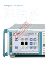
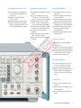
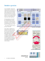
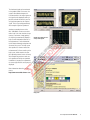
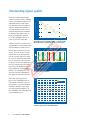
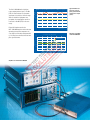
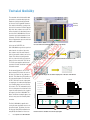
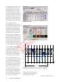
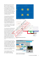
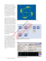
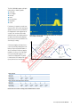
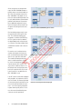
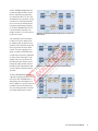
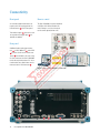
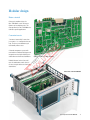
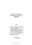
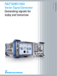
Test Equipment Solutions Datasheet Test Equipment Solutions Ltd specialise in the second user sale, rental and distribution of quality test & measurement (T&M) equipment. We stock all major equipment types such as spectrum analyzers, signal generators, oscilloscopes, power meters, logic analysers etc from all the major suppliers such as Agilent, Tektronix, Anritsu and Rohde & Schwarz. We are focused at the professional end of the marketplace, primarily working with customers for whom high performance, quality and service are key, whilst realising the cost savings that second user equipment offers. As such, we fully test & refurbish equipment in our in-house, traceable Lab. Items are supplied with manuals, accessories and typically a full no-quibble 2 year warranty. Our staff have extensive backgrounds in T&M, totalling over 150 years of combined experience, which enables us to deliver industry-leading service and support. We endeavour to be customer focused in every way right down to the detail, such as offering free delivery on sales, covering the cost of warranty returns BOTH ways (plus supplying a loan unit, if available) and supplying a free business tool with every order. As well as the headline benefit of cost saving, second user offers shorter lead times, higher reliability and multivendor solutions. Rental, of course, is ideal for shorter term needs and offers fast delivery, flexibility, try-before-you-buy, zero capital expenditure, lower risk and off balance sheet accounting. Both second user and rental improve the key business measure of Return On Capital Employed. We are based near Heathrow Airport in the UK from where we supply test equipment worldwide. Our facility incorporates Sales, Support, Admin, Logistics and our own in-house Lab. All products supplied by Test Equipment Solutions include: - No-quibble parts & labour warranty (we provide transport for UK mainland addresses). - Free loan equipment during warranty repair, if available. - Full electrical, mechanical and safety refurbishment in our in-house Lab. - Certificate of Conformance (calibration available on request). - Manuals and accessories required for normal operation. - Free insured delivery to your UK mainland address (sales). - Support from our team of seasoned Test & Measurement engineers. - ISO9001 quality assurance. Test equipment Solutions Ltd Unit 8 Elder Way Waterside Drive Langley Berkshire SL3 6EP T: +44 (0)1753 596000 F: +44 (0)1753 596001 Email: [email protected] Web: www.TestEquipmentHQ.com Product brochure Version Version 02.03 01.00 Vector Signal Generator ¸SMU200A The art of signal generation September November 2006 2004 Highlights of a new generation The Vector Signal Generator ¸SMU200A has been designed to meet all requirements encountered in research and development of modern communications systems as well as in their production. The ¸SMU200A not only combines up to two independent signal generators in one cabinet of only four height units – it also offers unrivaled RF and baseband characteristics. Vector Signal Generator ¸SMU200A Due to its modular design, the ¸SMU200A can be optimally adapted to the requirements of different applications. The first RF path can be equipped with one of the four available frequency options. The upper frequency limit of 2.2 GHz/3 GHz/4 GHz or 6 GHz is user-selectable. In addition, a second RF path can be installed with upper frequency limits of 2.2 GHz and 3 GHz. The lower frequency limit of all frequency options is 100 kHz. Up to two generators can also be installed in the baseband section. They generate complex signals in realtime and are equipped with an arbitrary waveform generator with 64 Msample memory for I and Q (256 Mbyte). The signals generated in the different basebands can be added. Frequency offset of the individual signals is possible. The modern, intuitive concept of the ¸SMU200A ensures fast and easy operation. Two signal generators in one Outstanding signal quality Unrivaled flexibility ◆ Frequency options from 100 kHz to 2.2 GHz/3 GHz/4 GHz/6 GHz for the first RF path ◆ Optional second RF path up to 2.2 GHz or 3 GHz ◆ Up to two complete baseband paths ◆ Lossless combination of baseband signals in the digital domain (e.g. for testing multistandard base stations) ◆ I/Q modulator with 200 MHz RF bandwidth ◆ Very low SSB phase noise of typ. –135 dBc (f = 1 GHz, 20 kHz carrier offset, 1 Hz measurement bandwidth) ◆ Wideband noise of typ. –153 dBc (CW, f = 1 GHz, >5 MHz carrier offset, 1 Hz measurement bandwidth) ◆ Excellent ACLR of typically +70 dB for 3GPP FDD (test model 1, 64 DPCHs) ◆ Very high level repeatability of 0.05 dB ◆ High output power up to +19 dBm (PEP), overrange +26 dBm ◆ High-stability reference oscillator as standard ◆ Four code channels in realtime for 3GPP FDD ◆ Change of modulation from slot to slot for GSM/EDGE ◆ Baseband generator with universal coder for realtime signal generation ◆ Arbitrary waveform generator with 64 Msamples for I and Q (256 Mbyte) ◆ Arbitrary waveform generator supported by Simulation Software ¸WinIQSIM™ ◆ Optional fading simulator with up to 40 fading paths Intuitive operation ◆ Color display with 800 × 600 pixels (SVGA format) ◆ Intuitive user interface with graphical display of signal flow (block diagram) ◆ Graphical display of baseband signals through built-in transient recorder ◆ Context-sensitive help system Ideal for production ◆ Very short frequency setting times (<3 ms); only 450 µs in List mode ◆ Electronic attenuator up to 6 GHz ◆ Minimum space required as two complete generators are accommodated in one cabinet of only four height units Connectivity ◆ Can be remote-controlled via GPIB and LAN ◆ USB connectors for keyboard, mouse and memory stick ◆ User-selectable trigger and marker signals Vector Signal Generator ¸SMU200A Intuitive operation The ¸SMU200A is equipped with a modern and intuitive user interface. The signal flow from the baseband to the RF output is clearly shown in the block diagram. Each block represents a functional unit of the instrument. The generated signal can be seen at a glance, including whether it is affected by additive white Gaussian noise or other impairments. The rotary knob plays a central role in ¸SMU200A operation. It allows the instrument to be operated with one hand. Any task – whether navigating in the block diagram or menus, selecting of parameters or toggling between states – can be performed simply by turning or pressing the rotary knob. Block diagram of the ¸SMU200A Active windows are indicated by a labeled button in the Winbar at the bottom of the screen. With the softkey below, the respective window can be quickly brought to the foreground. This allows rapid navigation between different windows. It is possible, for instance, to simultaneously display two slots of a GSM/EDGE system and to toggle between them. Windows can of course also be automatically arranged (REARR), hidden (HIDE) or closed (CLOSE) by means of hardkeys. Tool tip for permissible frequency setting range Turn Click Rotary knob for navigation in the menus Softkeys and hardkeys of the ¸SMU200A for windows management Vector Signal Generator ¸SMU200A The baseband signal can be monitored in the graphics block. For instance, the vector or constellation diagram, the I/Q characteristic or the output spectrum of a signal can be displayed, making it possible to check whether the generated signal corresponds to the required signal. This is of great help particularly when complex signals are produced. Another outstanding feature of the ¸SMU200A is its context-sensitive online help. If the exact function of a parameter is not known, simply pushing the help key instantaneously displays a help text with information about the selected parameter. Further information can be obtained through navigation with a browser-like system. The help system also specifies the relevant remote-control commands. Full-text searching in the help system, which contains the complete operating manual, comes in handy when complex measurement tasks are to be performed. Tool tips are provided in addition. If you pause on a parameter, the currently permissible setting range is displayed. Graphics block with I/Q, vector and spectrum diagram More information about the user interface at http://www.smu.rohde-schwarz.com/ Help system Vector Signal Generator ¸SMU200A Outstanding signal quality Amplifiers of 3GPP base stations require very good adjacent channel leakage ratio (ACLR) performance in order not to impair the adjacent channels of the transmission. To test this feature, the ACLR characteristics of the signal generator must be better than those of the amplifier. Presently, multicarrier power amplifiers are increasingly used. In this case, not only one but several neighboring signals in the frequency range are amplified. Testing such amplifiers places even higher demands on signal generator capabilities. The outstanding ACLR characteristics of the ¸SMU200A more than qualify the generator for this task. When external I/Q signals are applied, the ¸SMU200A features an RF bandwidth of 200 MHz. If the internal baseband is used, an RF bandwidth of 80 MHz is available, which is ideal for testing multicarrier amplifiers. The ¸SMU200A is thus well prepared for future broadband systems. SSB phase noise / dBc (1 Hz) –40 –50 –60 –70 –80 –90 –100 –110 –120 –130 –140 –150 –160 5,7 GHz 2,1 GHz 850 MHz 100 MHz 1 10 2 3 10 10 10 4 10 5 10 6 10 Typical SSB phase noise at 100 MHz, 850 MHz, 2.1 GHz and 5.7 GHz with internal reference oscillator (without low phase noise option) Ref -9.5 dBm * Att * RBW 30 kHz * VBW 300 kHz * SWT 2 s 10 dB -9.45 -20 A -30 SGL -40 1 RM * CLRWR -50 -60 -70 -80 NOR -90 -100 Center 2.16 GHz Span 25.5 MHz PRN 2.55 MHz/ Tx Channel Bandwidth 3.84 MHz W-CDMA 3GPP FWD Adjacent Channel Bandwidth Spacing 3.84 MHz 5 MHz Lower Upper -70.03 dB -70.40 dB Alternate Channel Bandwidth Spacing 3.84 MHz 10 MHz Lower Upper -72.96 dB -73.42 dB Power -6.03 dBm Outstanding ACLR characteristics 5 RF 850 MHz RF 1900 MHz RF 2200 MHz 4 3 2 1 0 -1 -2 -3 -4 -5 -100 -80 -60 -40 -20 0 20 Frequency offset from carrier / MHz 40 Frequency response (mode: external wideband I/Q) Vector Signal Generator ¸SMU200A 7 Frequency offset / Hz Delta / dB Owing to the sophisticated multiloop synthesizer concept, the ¸SMU200A features extremely low SSB phase noise and wideband noise. A high-stability oven-controlled reference oscillator is installed as standard, which provides excellent aging characteristics as well as minimum temperature drift. In addition, the low phase noise option further enhances the performance significantly. The ¸SMU200A is ideal, for instance, for LO or VCO substitution. 60 80 100 Available Power, Attenuator Mode Normal (lower trace) and High Power (upper trace) 30 28 Level / dBm The ¸SMU200A offers highly accurate output power of up to +13 dBm (PEP). A wear-and-tear-free electronic attenuator is used in the full level range. With the aid of the high-power output option, the output power can be increased to +26 dBm (PEP) in the overrange. 26 24 Typical maximum output power versus frequency (with and without high-power output option) 22 20 18 16 14 12 10 Digital ALC implemented in the ¸SMU200A together with a detector operating at constant temperature ensures high level linearity and repeatability. ALC may be on for most kinds of complex signal scenarios. 0 0.5 1.0 1.5 2.0 2.5 Frequency / GHz 3.0 High level repeatability of the ¸SMU200A Level repeatability (2 GHz, 0 dBm, ALC=ON) 0.03 CW Internal baseband I/Q External wideband I/Q 0.02 Level deviation/dB 0.01 0 -0.01 -0.02 -0.03 0 1 2 3 Time/hours 4 5 6 Amplifier test with the ¸SMU200A Vector Signal Generator ¸SMU200A Unrivaled flexibility The standards of the third mobile radio generation set considerably higher demands on signal generator functionality. Because of their good RF characteristics and their flexibility, signal generators are the instrument of choice particularly when base stations are tested. The universal coder in the baseband generator of the ¸SMU200A has been designed for easy implementation of new standards. The ¸SMU200A is therefore well prepared for present and future mobile radio standards. Realtime channels Four code channels in realtime with additional background channels For the control channels, the transmit power control (TPC) field of the individual slots of a frame can be read from a data list. This allows long TPC profiles to be generated for power-level control in the DUT. With this feature, output power ramping or the maximum output power of a mobile phone can be measured, for instance. The TPC information can also be used for power-level control in the respective code channel of the signal to be output by the ¸SMU200A. This allows simulation of complex power scenarios as may occur for a mobile phone in motion. The ¸SMU200A is capable of inserting bit errors and block errors in the generated signal. This allows the internal bit error ratio (BER) and block error ratio (BLER) calculations of a base sta Vector Signal Generator ¸SMU200A The mobile phone changes its output power in compliance with TPC information from the ¸SMU200A The ¸SMU200A changes the code channel output power on the basis of the TPC field DTCH DCCH CRC16 244 Information data DATA CRC attachment 16 CRC12 100 Tail8 CRC 244 Tail bit attachment 100 8 100 686 308 1st interleaving 686 308 Bit error 1 1 0 1 … 0 12 8 1 0 360 Rate matching 0 Tail8 12 804 Conv. coding R=1/3 Transmission In the case of 3GPP FDD, the ¸SMU200A can generate up to four code channels in realtime. Up to four base stations with 128 code channels each or four mobile stations can be simulated. This allows any configuration to be set, from reference measurement channels in line with 3GPP TS 25.141 or TS 25.101 up to complex code channel scenarios for traffic simulation in the mobile radio network. Block error 1 0 1 Insertion of bit errors and block errors into the output signal 1 0 1 … 1 tion to be checked in line with TS 25.141. The number of required bit and block errors can be set in the ¸SMU200A. Because of generation in realtime, continuous measurements of BER and BLER can be carried out without wrap-around problems. The receiver of a mobile phone must of course also function under real operating conditions. To check this, orthogonal background and interfering channels of a base station can be simulated in line with TS 25.101. The power of these channels is automatically configured so that the total output power of the base station remains unchanged. This allows measurements of the maximum input level in line with TS 25.101, for instance. The base station must also be tested under real conditions. In this case, up to 64 mobile phones can be configured in addition to the four user-configurable ones. The 64 mobile phones use different scrambling codes. Since the universal coder in the ¸SMU200A is extremely flexible, signals for high-speed downlink packet access (HSDPA) are generated without problems. Test model 5 with all its versions, as defined in TS 25.141 of the 3GPP specification, is also supported. Additional mobile stations for testing a base station receiver (green: background, red: user) Display of 3GPP FDD menu and code domain with two HSDPA data channels The test case wizard of the ¸SMU200A allows one-button base station testing. By simply choosing the required test case as defined in TS 25.141, the complete generator will be set up in accordance with the specification. All specific parameters, such as noise level, fading profile, and interfering signal are set without having to look them up in the standard document. The automatic setup includes the wanted signal, frequency offset and power level as well as interfering signals, noise and fading conditions. To test beyond the specifications, the parameters can also be adjusted. Test case wizard: intermodulation characteristics with display of signal setup Vector Signal Generator ¸SMU200A For receiver power measurements, the ¸SMU200A generates access, control and traffic channels of the various radio configurations in the 1× mode. Since channel coding is fully implemented in the ¸SMU200A, no additional bit error ratio testers are necessary. By evaluating the CRC fields, the base station is able to perform the frame error ratio (FER) measurement specified in the standard directly on the received signal. CDMA2000® channel table 1) In the forward link mode, the ¸SMU200A supports a total of four user-selectable base stations for each carrier frequency. Each simulated base station provides all control channels of the standard and up to eight independently configurable traffic channels. Any radio configuration can be selected for these channels. The channel coding can be set for each fundamental, supplemental and dedicated control subchannel of a traffic channel in any manner within the parameters defined by the standard. Thus, complex test scenarios can be set up that far exceed the mobile station tests defined in the 3GPP2 C.S00011‑B specification. The ¸SMU200A supports receiver tests by providing a fully channel-coded F-PDCH. The F-PDCCHs, which are indispensable for demodulation, are provided in duplicate. In addition to the packet channels, all regular control and user channels can also be activated. When the GSM/EDGE option is used, even the modulation can be changed between GMSK and 8PSK EDGE in realtime as may be the case in GSM/EDGE base stations. All burst types defined by the standard can be generated. In addition, up to eight different levels can be defined for the timeslots. A separate level can thus be assigned to each slot of a GSM frame. Furthermore, the ¸SMU200A permits two frames to be defined. The frame repetition rate can be set by the user as required. P7 P6 P5 P4 P3 P P1 Slot 0 1 3 4 5 Vector Signal Generator ¸SMU200A 7 0 1 Frame Change of modulation and different power levels in each slot for GSM/EDGE The change from GMSK to 8PSK EDGE modulation in a timeslot over time can thus be simulated, for instance. 1) 10 6 CDMA2000® is a registered trademark of the Telecommunications Industry Association (TIA -USA). When receivers are tested, it must be possible to simulate real receive conditions. In the ¸SMU200A, additive white Gaussian noise (AWGN) can be superimposed on the wanted signal. The signal-to-noise ratio can be set in a wide range. Thus, highly accurate sensitivity measurements can be performed on receivers with a defined S/N ratio, in compliance with 3GPP specifications TS 25.141 and TS 25.101. The internal arbitrary waveform generator (ARB) with its large 56 Msample memory for I and Q (and 4 marker bits per sample) and a clock rate of 100 Msample/s offers ideal conditions for generating complex signal scenarios. Due to the implemented hardware resampling, lower oversampling rates can be used so that less memory is required for storing waveforms. Therefore longer sequences are possible. Test systems often switch back and forth between various test signals. The time necessary to switch between these signals can be minimized by combining individual waveforms into a multisegment waveform. The complete multisegment waveform is loaded into the ARB memory, and each segment then represents a separate waveform. This eliminates the loading time that would otherwise be necessary when switching between segments. Constellation diagram of a noisy signal Waveform 1 Automatic repetition of partial waveform within segment Resulting waveform in output RAM Waveform 2 Segment 1 Segment 2 Segment 3 Output signal Waveform 3 Segment switching by ¸SMU user interface, IEC/IEEE bus, external trigger line How the multisegment waveform operates The internal arbitrary waveform generator of the ¸SMU200A is supported by Simulation Software ¸WinIQSIM™. With ¸WinIQSIM™, signals can be easily generated for WLAN systems such as IEEE 802.11a/b/g, TDMA systems such as GSM/EDGE and even complex CDMA systems such as TD-SCDMA. Multicarrier signals can also be generated. For more information, refer to the data sheet for Simulation Software ¸WinIQSIM™ (PD 0758.0680). Simulation Software ¸WinIQSIM™ Vector Signal Generator ¸SMU200A 11 When signals are sent from the transmitter to the mobile receiver, various fading effects occur. Thus, multiple propagation paths may be superimposed on each other either constructively or destructively. In addition, the movement of the receiver relative to the transmitter creates a frequency shift. The ¸SMU200A fading simulator makes it easy to simulate these conditions in the lab. This is the only way to optimize receiver performance. A total of 40 fading paths at 80 MHz bandwidth and 10 ns time resolution are available for simulating multipath propagation. If higher time resolution is needed (10 ps), the bandwidth (30 MHz and 50 MHz) and the number of fading paths (24 and 16) can be modified. Since up to two baseband generators and RF paths can be installed on the ¸SMU200A, it is easy to simulate the receive conditions of a receiver that has two antennas (e.g. a UMTS base station). This eliminates the problems usually associated with cabling and synchronization since the entire scenario is created in a single ¸SMU200A. The user interface was designed for easy and straightforward operation. Thus, it includes fading profiles for the most common mobile radio standards (e.g. GSM/EDGE, 3GPP, CDMA, TETRA, WLAN). To handle special test requirements, the fading profiles can also be configured as needed. The graphical display of the fading paths provides an overview of the situation at all times. It shows the number of paths, timing, relative power and the fading profile that is used. Rician fading of a squarewave-filtered QPSK signal (change in amplitude and phase) Setup for simulating transmit diversity with fading Simplest setting of the preferred fading 12 Vector Signal Generator ¸SMU200A The ¸SMU200A supports multipath fading with the following profiles: ◆ Static path ◆ Pure Doppler ◆ Rayleigh ◆ Rician ◆ Constant phase ◆ Lognormal ◆ Suzuki A frequency hopping technique that resumes the preceding fading process following a frequency hop-back allows realistic simulation of frequency hopping conditions. In this case, the calculation of the preceding fading process is resumed in the background. The profile is continued as if the fading at this frequency had not been interrupted. Demonstration of moving delay fading with ASK modulation: the second path moves relative to the first path Power Furthermore, it supports scenarios introduced by 3GPP such as birth-death propagation (testing of receiver performance for disappearance and reappearance of a signal, such as when a caller walks around the corner of a building while on the phone) and moving delay propagation (testing of receiver performance for slow changes in delay). Profile for frequency f2 Frequency hopping f1 to f2 Internal calculation of profile f1 1 8 50 MHz 10 ps Signal paths Fading paths RF bandwidth Time resolution 1 16 50 MHz 10 ps 1 24 30 MHz 10 ps Frequency hopping f2 to f1 Internal calculation of profile f2 Time Fading Simulator Signal paths 1 1 Fading paths 20 12 RF bandwidth 80 MHz 30 MHz Time resolution 10 ns 10 ps Fading Simulator with Fading Simulator Extension 1 40 80 MHz 10 ns Continued profile for frequency f1 Profile for frequency f1 2 20 80 MHz 10 ns 2 12 30 MHz 10 ps 2 8 50 MHz 10 ps Relation between the number of fading paths, bandwidth and time resolution Vector Signal Generator ¸SMU200A 13 All the strengths of the two-path concept of the ¸SMU200A become especially evident in the field of mobile radio. Since the baseband section of the ¸SMU200A is fully digital, the signals of the two baseband generators can be easily added without synchronization problems and without an external coupler or additional equipment being required. A frequency offset and the relative power of each signal can be accurately set. Generation of 3GPP and GSM/EDGE signals in realtime One baseband generator may be used for generating the 3GPP signal in realtime. The second baseband generator produces a realtime GSM/EDGE signal. The signals can then be added in the digital domain with a frequency offset, if desired. This allows modern multistandard base stations to be tested, for instance. For receiver tests in multicarrier base stations with complex interfering signals, one baseband generator can produce the test signal to be evaluated. The second baseband generator produces a suitable multicarrier signal to be used as the background signal. Two transmit antennas (the transmit diversity) of a base station can also be simulated. Up to now, two signal generators have been required in this case, but only one instrument is needed when the ¸SMU200A is used. If the RF section is furthermore equipped with two paths, any requirement can be met. For instance, the wanted signal and the interfering signal needed for receiver tests can be generated with one instrument – even if the signals greatly differ in power and frequency offset as is the case when out-of-band blocking measurements are to be performed. 14 Vector Signal Generator ¸SMU200A Adding a realtime signal and a multicarrier signal Generation of wanted signal and interfering signal An ¸SMU200A equipped with fading and noise options contains all components required for the performance tests specified in 3GPP TS 25.141. Since all components are integrated in a single instrument, the effort that would otherwise be necessary for cabling and timeconsuming synchronization is eliminated. The ¸SMU200A 3GPP FDD Test Case Wizard makes it possible to set complex scenarios even such as these at the press of a button. Since signal paths can be switched as needed, even after the fading simulator, complex signal scenarios that were previously either not possible or possible only at great effort can now be implemented. This makes it possible, for example, to simulate a GSM/EDGE frame in which only one timeslot is faded while the others remain unchanged. The appropriate frames are generated in the baseband generators and then routed through the fading simulator. Only one baseband signal is faded and then added to the signal of the other baseband generator. Generation of a 3GPP signal followed by fading and noise as specified in 3GPP TS 25.141 Generation of a GSM/EDGE frame with faded and unfaded timeslots The ¸SMU200A BBIN option makes it possible to feed external analog I/Q signals into the ¸SMU200A and then apply fading, noise and impairments to them. In addition, the external signal can be added to the internal baseband signals, thus making it possible to simulate even highly complex signal scenarios. Addition of external I/Q signals to internal baseband signals Vector Signal Generator ¸SMU200A 15 Connectivity Front panel Remote control An external keyboard and a mouse or memory stick can be plugged into the USB connectors on the front panel. The ¸SMU200A is remote-controlled via GPIB or LAN. When Windows Remote Desktop is used, the instrument can be remote-operated from a PC. Two marker outputs that can be used as required and a trigger input are available in addition. Rear panel Additional marker and trigger connectors , a LAN (100BaseT) and a GPIB interface as well as a USB slave connector are available at the rear. Using the slave connector, the ¸SMU200A can be directly connected to a PC. An external monitor or a video beamer can be connected to the VGA connector . Remote control of the ¸SMU200A via GPIB or LAN 16 Vector Signal Generator ¸SMU200A Modular design Future-oriented Owing to its modular design, the ¸SMU200A is a safe investment. Options can be added any time. This concept allows the ¸SMU200A to be tailored to specific applications. Convenient service “Low cost of ownership” is more than just a motto – it is a comprehensive concept. The three-year calibration cycle considerably reduces costs. A thermal management system with oversized fans combined with large-scale integration ensures high reliability even under adverse environmental conditions. Synthesizer module of the ¸SMU200A Rohde & Schwarz Service Centers all over the world reduce transit times in the case of repair and ensure short turnaround times. Internal view of the ¸SMU200A Vector Signal Generator ¸SMU200A 17 Specification summary Frequency Frequency range Setting time 100 kHz to 2.2 GHz/3 GHz/4 GHz/ 6 GHz <3 ms Setting time in List mode <450 µs Level Range Range with high-power output option Spectral purity (at f = 1 GHz) Nonharmonics Carrier offset >10 kHz Carrier offset >850 kHz SSB phase noise (20 kHz carrier offset, 1 Hz measurement bandwidth) Wideband noise (carrier offset >5 MHz, 1 Hz measurement bandwidth) ACLR 3GPP test model 1, 64 DPCHs –145 dBm to +13 dBm (PEP, 3 GHz) –145 dBm to +19 dBm (PEP, 3 GHz) <–80 dBc <–86 dBc typ. –135 dBc typ. –153 dBc (CW) typ. –149 dBc (I/Q modulation) typ. 70 dB RF modulation bandwidth Using external I/Q inputs 200 MHz Using internal baseband section 80 MHz Supported modulation types AM DC to 500 kHz Pulse 0 kHz to 100 kHz ASK 0 % to 100 % FSK MSK, 2FSK, 4FSK PSK BPSK, QPSK, OQPSK, π/2 DBPSK, p/4 DQPSK, p/8 D8PSK, p/4 QPSK, 8PSK, 8PSK EDGE 16QAM, 32QAM, 64QAM, 256QAM, 1024QAM GSM/EDGE, 3GPP FDD, 3GPP TDD, TD-SCDMA, cdmaOne, CDMA2000®, 1 × EV-DO, IEEE 802.11a, IEEE 802.11b, IEEE 802.11g, TETRA, Bluetooth® 2), AWGN, user-defined multicarrier CW IEEE 488.2, LAN (100BaseT), 3 × USB, 1 × USB slave, VGA QAM Supported standards and digital systems Interfaces 2) The Bluetooth® word mark and logos are owned by the Bluetooth SIG, Inc. and any use of such marks by Rohde & Schwarz is under license. 18 Vector Signal Generator ¸SMU200A Ordering information Designation Vector Signal Generator1) including power cable, Quick Start Guide and CD-ROM (with operating and service manual) Options RF Path A 100 kHz to 2.2 GHz 100 kHz to 3 GHz 100 kHz to 4 GHz 100 kHz to 6 GHz FM/ϕM Modulator FM/ϕM Modulator and Low Phase Noise Overvoltage Protection High-Power Output Overvoltage Protection and High-Power Output RF Path B 100 kHz to 2.2 GHz 100 kHz to 3 GHz Overvoltage Protection High-Power Output Overvoltage Protection and High-Power Output Baseband Baseband Generator with ARB (128 Msample) and Digital Modulation (realtime) Baseband Generator with ARB (64 Msample) and Digital Modulation (realtime) Baseband Generator with ARB (16 Msample) and Digital Modulation (realtime) Baseband Main Module Differential I/Q Output Analog Baseband Input Digital modulation systems Digital Standard GSM/EDGE Digital Standard 3GPP FDD 3GPP Enhanced MS/BS Tests incl. HSDPA Digital Standard GPS 3GPP FDD HSUPA Digital Standard CDMA2000® incl. 1xEV-DV Digital Standard IEEE 802.11 (a/b/g) Digital Standard IEEE 802.16 Digital Standard TD-SCDMA TD-SCDMA enhanced BS/MS Tests Digital Standard DVB-H Multicarrier CW Signal Generation Digital modulation systems using ¸WinIQSIM2TM 2) Digital Standard GSM/EDGE Digital Standard 3GPP FDD 3GPP Enhanced MS/BS Tests incl. HSDPA Digital Standard GPS 3GPP FDD HSUPA Digital Standard CDMA2000® incl. 1xEV-DV Digital Standard IEEE 802.11 (a/b/g) Digital Standard IEEE 802.16 Digital Standard TD-SCDMA TD-SCDMA enhanced BS/MS Tests Multicarrier CW Signal Generation Type ¸SMU200A Order No. 1141.2005.02 ¸SMU-B102 ¸SMU-B103 ¸SMU-B104 ¸SMU-B106 ¸SMU-B20 ¸SMU-B22 ¸SMU-B30 ¸SMU-B31 ¸SMU-B32 1141.8503.02 1141.8603.02 1141.8703.02 1141.8803.02 1142.0006.02 1160.5006.02 1159.7444.02 1159.8011.02 1160.0256.02 ¸SMU-B202 ¸SMU-B203 ¸SMU-B35 ¸SMU-B36 ¸SMU-B37 1141.9400.02 1141.9500.02 1160.0633.02 1160.1000.02 1160.1400.02 ¸SMU-B9 ¸SMU-B10 ¸SMU-B11 ¸SMU-B13 ¸SMU-B16 ¸SMU-B17 1161.0766.02 1141.7007.02 1159.8411.02 1141.8003.04 1161.0066.02 1142.2880.02 ¸SMU-K40 ¸SMU-K42 ¸SMU-K43 ¸SMU-K44 ¸SMU-K45 ¸SMU-K46 ¸SMU-K48 ¸SMU-K49 ¸SMU-K50 ¸SMU-K51 ¸SMU-K52 ¸SMU-K61 1160.7609.02 1160.7909.02 1160.9660.02 1161.0566.02 1161.0666.02 1160.9876.02 1161.0266.02 1161.0366.02 1161.0966.02 1161.1062.02 1408.7010.02 1160.8505.02 ¸SMU-K240 ¸SMU-K242 ¸SMU-K243 ¸SMU-K244 ¸SMU-K245 ¸SMU-K246 ¸SMU-K248 ¸SMU-K249 ¸SMU-K250 ¸SMU-K251 ¸SMU-K261 1408.5518.02 1408.5618.02 1408.5718.02 1408.5818.02 1408.5918.02 1408.6014.02 1408.6114.02 1408.6214.02 1408.6314.02 1408.6414.02 1408.6514.02 Vector Signal Generator ¸SMU200A 19 Digital modulation systems using ¸WinIQSIMTM 3) Digital Standard IS-95 (with ¸WinIQSIMTM) Digital Standard CDMA2000® (with ¸WinIQSIMTM) Digital Standard 3GPP TDD (with ¸WinIQSIMTM) Digital Standard TD-SCDMA (with ¸WinIQSIMTM) User-Defined OFDM Signals (with ¸WinIQSIMTM and ¸WinIQOFDM) Digital Standard 1xEV-DO (with ¸WinIQSIMTM) Digital Standard IEEE 802.11 (a/b/g) (with ¸WinIQSIMTM) Digital Standard 3GPP FDD incl. HSDPA (with ¸WinIQSIMTM) Digital modulation systems using external PC software Digital Standard Bluetooth® Fading Simulator Fading Simulator Extension Additive White Gaussian Noise (AWGN) Dynamic Fading and Enhanced Resolution Other options BER/BLER Measurement Rear panel connectors for 1st RF path Rear panel connectors for 2nd RF path Recommended extras Hardcopy manuals (in German) Hardcopy manuals (in English, UK) Hardcopy manuals (in English, USA) 19" Rack Adapter Adapter for Telescopic Sliders BNC Adapter for AUX I/O Connector Keyboard with USB Interface (US assignment) Mouse with USB Interface, optical External USB CD-RW Drive ¸SMU-K11 ¸SMU-K12 ¸SMU-K13 ¸SMU-K14 ¸SMU-K15 ¸SMU-K17 ¸SMU-K19 ¸SMU-K20 1160.5335.02 1160.5658.02 1160.5906.02 1160.6202.02 1160.6402.02 1160.7009.02 1160.8805.02 1160.9460.02 ¸SMU-K5 ¸SMU-B14 ¸SMU-B15 ¸SMU-K62 ¸SMU-K71 1161.0466.02 1160.1800.02 1160.2288.02 1159.8511.02 1160.9201.02 ¸SMU-K80 ¸SMU-B81 ¸SMU-B82 1159.8770.02 1159.9001.02 1159.9501.02 ¸ZZA-411 ¸ZZA-T45 ¸SMU-Z5 ¸PSL-Z2 ¸PSL-Z10 ¸PSP-B6 1007.9845.31 1007.9845.32 1007.9845.39 1096.3283.00 1109.3774.00 1160.4545.02 1157.6870.04 1157.7060.03 1134.8201.22 The base unit can only be ordered with an ¸SMU-B10x frequency option. ¸WinIQSIM2 TM requires an external PC. 3) R&S WinIQSIM requires an external PC. 1) 2) For specifications, see PD 0758.0197.22 and www.rohde-schwarz.com (search term: SMU) Certified Quality System Certified Environmental System ISO 9001 ISO 14001 DQS REG. NO 1954 QM DQS REG. NO 1954 UM www.rohde-schwarz.com Europe: +49 1805 12 4242, [email protected] USA and Canada: 1-888-837-8772, [email protected] Asia: +65 65130488, [email protected] ¸is a registered trademark of Rohde & Schwarz GmbH & Co. KG · Trade names are trademarks of the owners · Printed in Germany (ed/we/ch) PD 0758.0197.12 · ¸SMU200A · Version 02.03 · September 2006 · Data without tolerance limits is not binding · Subject to change Ordering information (continued)