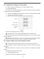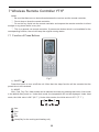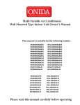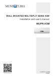
1
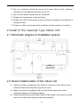
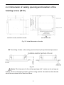
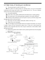
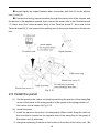
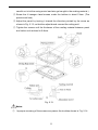
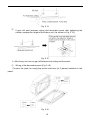
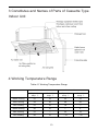
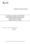
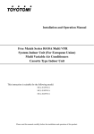
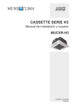
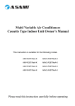
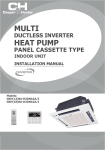
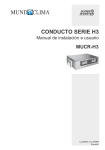
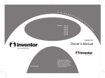
MULTISPLIT CASSETTE H3M Installation and user's manual MUCSR-H3M www.mundoclima.com CL20824 to CL20826 English User Notice When operating, the entire capacity of the cooperating indoor unit should be not larger than 150% of outdoor unit. Otherwise, it will cause the shortage of cooling (heating) capacity. The total capacity of the indoor units which runs at the same time can not exceed 150% of that of the outdoor units, otherwise, the cooling (heating) effect of each indoor unit would be poor. Switch the main power on 8 hours before starting the unit, helpful for a successful startup. A Breaker (or fuse) need to be installed in every indoor unit, and the capacity should in according with indoor unit’s electrical parameter; all the indoor units are required to be centralized controlled by a total Switch, this Switch can cut off the electric power supply in case of emergency. The Breaker (or fuse) on each indoor units have the function of short circuit prevention and abnormal overload avoiding, it should be connected in normal situation. The total switch controlling the power supply of all the indoor units. Before clearing and maintenance job being carried out to the indoor units, it is very important to turn off the total power supply switch. In order to turn on the units successfully, the main power switch should be opened 8 hours before the operation. After receiving the turn off signal, every indoor unit will continue to work for 20-70sec to make use of the rest cool air or the rest heat air in the heat exchanger, while preparing for the next operation. And this is normal. When the selected operating mode of the indoor unit are clash with the operating mode of the outdoor unit, the malfunction light will blink after 5s on the indoor unit or remote controller showing that the operation clash, then the indoor unit will stop. At this time, change the operation mode of the indoor unit to the one that would not clash with the outdoor operating mode to make the operation n ormal. The cooling mode is not clash with the dry mode, while the fan mode is not clash with any mode. The appliance shall not be installed in the laundry An all-pole disconnection switch having a contact separation of at least 3mm in all poles should be connected in fixed wiring Information regarding transport/storage temperature (-25-55°C) is missing Main switch provided by end user: main switch handle should be black or gray, it can be locked in “OFF” position with padlock The main disconnection device s hould be explained in user manual and the height should be recommended at 0.6-1.7m. Over current protection is required(EN 60947-3, EN 60947-2) The cooling range of the unit is the outdoor environment temp.-5~48°C DB, the heating range of the unit ( only for the heat pump type unit) is the outdoor environment temp. -15~27°C WB. This appliance can be used by children aged from 8 years and above and persons with reduced physical, sensory or mental capabilities or lack of experience and knowledge if the y ha ve been given supervision or instruction concerning use of the appliance in a safe way and understand the hazards involved. Children shall not play with the appliance. Cleaning and user maintenance shall not be made by children without supervision. If the supply cord is damaged, it must be replaced by the manufacturer, its service agent or similarly qualified persons in order to avoid a hazard. The appliance shall be installed in accordance with national wiring regulations. Correct Disposal of this product This marking indicates that this product should not be disposed with other household wastes throughout the EU. To prevent possible harm to the environment or human health from uncontrolled waste disposal, recycle it responsibly to promote the sustainable reuse of material resources. To return your used device, please use the return and collection systems or contact the retailer where the product was purchased. They can environmental safe recycling. R410A (R32/125:50/50):2087.5 take this product for Contents 1 Safety Information ................................................................................. 1 2 Install of The Cassette Type Indoor Unit ................................................ 2 2.1 Schematic diagram of installation spaces ................................................................... 2 2.2 Select install location of the indoor unit ....................................................................... 2 2.3 Important notice ............................................................................................................... 3 2.4 Dimension of ceiling opening and location of the hoisting screw (M10) ................. 4 2.5 Main body of hoisting air conditioner............................................................................ 5 2.6 Connection of the refrigerant pipe ................................................................................ 6 2.7 Drainage hose.................................................................................................................. 7 2.8 Electrical wiring ................................................................................................................ 9 2.9 Install the panel.............................................................................................................. 10 3 Constitutes and Names of Parts of Cassette Type Indoor Unit ............. 13 4 Working Temperature Range ............................................................... 13 5 Malfunction Debarring ......................................................................... 14 5.1 Check the following items before contacting maintenance center ........................ 14 5.2 Instruction ....................................................................................................................... 15 5.3 The following circumstance are not malfunction ...................................................... 15 5.4 After-sales Service ........................................................................................................ 15 6 Maintenance Method ........................................................................... 16 6.1 Cleaning air filter............................................................................................................ 16 6.2 Clean air inlet grille........................................................................................................ 17 6.3 Install and change of air purifier .................................................................................. 18 6.4 Clean Outlet vent and Surface Panel......................................................................... 18 6.5 Maintenance before or after usage season............................................................... 19 7 Wireless Remote Controller Y T1F ........................................................ 20 7.1 Function of Press Buttons .......................................................................... 20 7.2 Guide for General Operation ...................................................................... 22 7.3 Guide for Optional Operation ..................................................................... 23 1 Safety Information Please read this manual carefully before use this unit, and operate it correctly according to the guide in this manual. Please take specially note to the meaning of these two marks: Warning!: This mark means that it may cause casualty or badly heart if the operation is incorrect. Note !: This mark means that it may cause casualty or property loss if the operation is incorrect. Warning: Do not adopt fuse with unsuitable capacity or adopt iron thread instead of fuse, otherwise malfunction or fire may happened. Cut down the main power switch immediately if malfunction (such as smell the burning odor etc.) happened. Maintain ventilation to prevent oxygen leakage in room. Don’t insert finger or stick like things into discharge vent or outlet grill. Please make sure that the unit is installed in the place that can bear the weight of it adequately. If the place is not strong enough, the air cond itioner may drop and cause casualty event. Don’t spray or smear any oil paint or insecticide on the surface of unit, otherwise, fire may be leaded. Do not refit the conditioner. Please contact the agency or prefect ional personnel to repair or move the conditioner. An all-pole disconnection switch having a contact separation of at least 3mm in all poles should be connected in fixed wiring. Note !: ①. Please check and make sure that the cord, drainage pipe and tubes are connected in the correct way to prevent leakage of water, refrigerant, electric shock or fire. ②. The main power must connectable to the earth in order to assure the conditioner earthing effectively and to prevent electric shock. Please don’t connect the earthing line with the gas pipe, water pipe, lightening rod or the connecting line of telephone. 1 ③. The air conditioner should be turned off at least after 5 mins’ operation , otherwise it would affect the duration of the unit. ④. Don’t let the children operate the air conditioner. ⑤. Please don’t operate the unit by wet hand. ⑥. Please turn off the main power of the unit before cleaning the conditioner or change the filter. ⑦. Please cut off the main power if the conditioner will be used for a long time. 2 Install of The Cassette Type Indoor Unit 2.1 Schematic diagram of installation spaces MUCSR-12-H3M MUCSR-18-H3M MUCSR-24-H3M Fig. 2.1 2.2 Select install location of the indoor unit (1) Obstruct should put away from the intake or outlet vent of the indoor unit so that the airflow can be blown though all the room. (2) Make sure that the installation had accord with the requirement of the schematic diagram of installation spaces. (3) Select the place where can stand 4 times of the weight of the indoor unit and would not increase the operating noise and oscillate. 2 (4) The horizontally of the installation place should be guaranteed. (5) Select the place where easy drain condensated coagulated water, and easy connect with outdoor unit. (6) Make sure that there are enough space for care and maintenance. Make sure that the weight between the indoor unit and ground is above 2500mm. (7) When installing the steeve bolt, check if the install place can stand the weight 4 times of the unit’s. If not, reinforce before installation. (Refer to the install cardboard and find where should be reinforced) Note ! There will be lots of lampblack and dust stick on the acentric, heat exchanger and water pump in dining room and kitchen, which would reduce the capacity of heat e xchanger, lead water leakage and abnormal operation of the water pump. The following treatment should be taken under this circumstance: (1) Ensure that the smoke trap above cooker has enough capacity to obviate lampblack to prevent the indraft of the lampblack by the air conditioner. (2) Keep the air conditioner far from the kitchen so that the lampblack would not be indraft by the air conditioner. 2.3 Important notice (1) To guarantee the good performance, the unit must be installed by professional personnel according with this instruction. (2) Please contact the local Mundoclima special nominated repair department before installation. Any malfunction caused by the unit that is installed by the department that is not special nominated by Mundoclima would not deal with on time by the inconvenience of the business contact. 3 2.4 Dimension of ceiling opening and location of the hoisting screw (M10) MUCSR-12-H3M, MUCSR-18-H3M MUCSR-24-H3M Fig. 2.2 Install dimension of mode The drilling of holes in the ceiling must be done by the professional personnel. Fig. 2.3 Notes: The dimension for the ceiling openings with * marks can be as large as 610mm. But the overlapping sections of the ceiling and the decorated surface boards should be maintained at no less than 20mm. 4 2.5 Main body of hoisting air conditioner (1) The primary step for install the indoor unit. When attach the hoisting stand on hoisting screw, d o use nut and gasket individually at the upper and lower of the hoisting stand to fix it. The use of gasket anchor board can prevent gasket break off. (2) Use install cardboard Please refer to the install cardboard about the dimension of ceiling opening. The central mark of the ceiling opening is marked on the install cardboard. Install the install cardboard on the unit by bolt (3 piece), and fix the angle of the drainage pipe at the outlet vent by bolt. (3) Adjust the unit to the suitable install place. (Refer to the Fig. 2.3) (4) Check if the unit is horizontal. Inner drainage pump and bobber switch are included in the indoor unit, check if 4 angle of every unit are horizontal by water le ver. (If the unit is slant toward the opposite of the coagulate water flow, there may be malfunction of the bobber switch and lead water drop.) (5) Backout the gasket anchor board used to prevent gasket break off and tighten the nut on it. (6) Backout the install cardboard. Fig. 2.4 5 Note ! Please do tighten the nuts and bolts to prevent air conditioner break off. 2.6 Connection of the refrigerant pipe When connect the pipe to the unit or backout it from the unit, please do use both spanner and torque wrench. as shown in Fig. 2.5. When connect, smear both inside and outside of the flare nut with freeze motor oil, screw it by hand and then tighten it with spanner. Refer to Table 2.1 to check if the wrench had been tightened (too tight would mangle the nut and lead leakage). Examine the connection pipe to see if it had gas leakage, then take the treatment of heat insulation, as shown in the Fig. 2.5. Only use median sponge to entwine the wiring interface of the gas pipe and heat preservation sheath of the gas collection tube. Fig. 2.5 Table 2.1: The tightening torque needed for tightening nut Diameter(Inch) Surface thickness(mm) Tightening torque (N·m) Φ1/4’’ ≥0.5 15-30 (N·m) Φ3/8’’ ≥0.71 30-40 (N·m) Φ1/2’’ ≥1 45-50 (N··m) Φ5/8’’ ≥1 60-65 (N·m) Φ3/4’’ ≥1 70-75 (N··m) 6 2.7 Drainage hose (1) Install the drain hose The diameter of the drain hose should be equal or bigger than the connection pipe’s. ( The diameter of polythene pipe: Outer diameter 25mm Surface thickness ≥ 1.5mm) Drain hose should be short and drooping gradient should at less 1/100 to prevent the formation of air bubble. If drain hose cannot has enough drooping gradient, drain raising pipe should be added. To prevent bent of the drain hose, the distance between hoisting stand should is 1 to 1.5m. Fig. 2.6 Use the drain hose and clamp attached. Insert the drain hose to the drain vent, and then tighten the clamp. Entwine the big sponge on the clamp of drain hose to insulate heat. Heat insulation should be done to indoor drain hose. Fig. 2.7 7 Drain stepup pipe note The install height of the drain raising pipe should less than 280mm. The drain raising pipe should form a right angle with the unit, and distance to unit should not beyond 300mm. Fig. 2.8 Instruction The slant gradient of the attached drain hose should be within 75mm so that the drain hole doesn’t has to endure the unnecessary outside force. Fig. 2.9 Please install the drain hose according to the following process if several drain hoses join together. Fig. 2.10 8 (2) Check the smoothness of drain after installation. Check the drain state by immitting 600cc water slowly from the outlet vent or test hole. Check the drain in the state of refrigerating after installation of the electric circuit. Fig. 2.11 2.8 Electrical wiring Note : The power of the entire indoor unit must be connected in outdoor unit. About the electrical wiring, please see the circuit diagram attached with the unit. All the installation of electrical wiring must be done by professional personnel. Please do take the earthing treatment. Wiring method of connection unit and controller Connection wiring (communication): ①. Open electric box cover (1), drag the wiring (communication) from the rubber plug A, and impact them well individually by impact fastener. ②. Wiring according to the indoor side circuit diagram . Fix the impact fastener after connection. Entwine the small sponge on the electric wire ( do entwine it to pre vent condensation) 9 Impact tightly by impact fastener after connection and then fit on the electric box (1) and (2). Connect the wiring (communication) through the piping hole of the chassis and the bottom of the appliance upward, then connect the brown wire to the Terminal board “3”, black wire (the communication wire) to the Terminal board“2”, blue wire to the Terminal board“N(1)”.and connect the earthing wire to the screw terminal on the electric box. Fig. 2.12 2.9 Install the panel (1) Set the panel to the indoor unit body by matching the position of the swing flap motor of the panel to the piping position of the panel to the piping position of the indoor unit as shown by Fig. 2.13. (2) Install the panel ①. Install the panel on the indoor unit temporarily. When install, hang the latch on the hook that is located on the opposite side of the swing flap on the panel of the indoor unit. (2 positions) ②. Hang the remaining 2 latches to the hooks on the sides of the indoor unit. (Be 10 careful not to let the swing motor lead wire get caught in the sealing material.) ③. Screw the 4 hexagon head screws under the latches in about 15mm. (The panel would rise) ④. Adjust the panel by turning it toward the direction pointed by the arrow as shown in Fig. 2.13, so that the adjust board connect the ceiling well. ⑤. Tighten the screws until the thickness of the sealing material between panel and indoor unit reduced to 5-8mm. Fig. 2.13 Notes: ①. Improper screwing of the screws may cause the troubles shown in Fig. 2.14. 11 Fig. 2.14 ②. If gap still exist between ceiling and decoration panel after tightening the screws, readjust the height of the indoor unit. (As shown in Fig. 2.15). Fig. 2.15 ※ After fi xing, be sure no gap left between the ceiling and the panel. ③. Wiring of the decoration panel (Fig. 2.16) Connect the joints for swing flap motor lead wire (at 2 places) installed on the panel. Fig. 2.16 12 3 Constitutes and Names of Parts of Cassette Type Indoor Unit 4 Working Temperature Range Table 4.1 Working Temperature Range Indoor side state Outdoor side stae Dry bulb temp. ℃ Wet bulb temp. ℃ Dry bulb temp. ℃ Wet bulb temp. ℃ Rated Cooling 27 19 35 24 Max. cooling 32 23 48 26 Min. cooling 21 15 18 — Rated Heating 20 15 7 6 Max. heating 27 — 24 18 Min. heating 20 15 -15 -16 13 5 Malfunction Debarring Warning! ①. Cut down the main power switch immediately if malfunction (such as smell the burning odor etc.) happened, and then contact service center. If the abnormal state is maintained, the unit may be damaged or electric shock or fire may be happened. ②. Do not refit the conditioner. Please contact service center to repair or move the conditioner. 5.1 Check the following items before contacting maintenance center Phenomena Air conditioner doesn’t run at all Air conditioner runs but stops immediately Abnormal cooling or heating Reason Remedial Measures Blow of fuse or breaker Change fuse or close brea ker Power cut Resta rt when there is power supply Don’t connect with power Connect power well Low batteries of wireless remote controller Change new batteries Wireless remote controller exceed remote control area Signal could be received within 8m Blockage in inlet or outlet vent of indoor or outdoor unit Clean out blockage Blockage in inlet or outlet vent of indoor or outdoor unit Clean out blockage Improper of temp. setting Adjust settings in wireless remote controller Low setting of fan speed Adjust settings in wireless remote controller Incorrect of wind direction Adjust settings in wireless remote controller Door or window opened Close Direct sun burn Hang curtain or jalousie before windows Too many people in room Too many heater in room Filter blocked by dirt 14 Clean filter 5.2 Instruction If problem still cannot found out after above checking, please contact service center and instruct phenomena and model. 5.3 The following circumstance are not malfunction “Malfunction” Reason Start up unit immediately after turned off The overload protects switch makes it run after 3 minutes delay. When opening power Run for about 1 minute without other actions When cooling The high humidity air in room is cooled rapidly Slight click sound heard once begin running Sound of initialization for electric expand valve Hissing sound heard continuously when cooling The sound for gas refrigerant flowing in the unit Hissing sound heard when staring or stopping The sound for gas refrigerant stop s flow Slight hissing sound heard when running or after running Sound for running of drainage system Crea k sound heard when running or after running The grating sound caused by expands of panel and other parts for the change of temperature Dust be blown for air conditioner Started up after long time’s doesn’t run s Dust in indoor unit be blown out Odor gives out from air conditioner When running This is becau se when air conditioning, odors or cigarette smoke from the room that was sucked in is discharged again. Air conditioner doesn’t run Mist is blown from air conditioner Noise is heard from air conditioner 5.4 After-sales Service When having quality or other problems when purchasing air conditioner, please contact the local service center. 15 6 Maintenance Method When air conditioner won’t be used for a long time, please cut off the main power supply of air conditioner. Warning! ①. Do turn off the unit and cut off the main power supply when cleaning the air conditioner, otherwise electric shock or harm may happen. ②. It is forbidden to wash air conditioner by water rinsing, otherwise electric shock may happen. 6.1 Cleaning air filter When the usage environment has lots of dust, air filter should be cleaned more frequently (about once 6 months). (1) Open air inlet grille Pull the 2 handle on air inlet grille at the same time with the direction showed by arrow in Fig. 6.1, pull down slowly. (Re verse when closing) (2) Disassembly air filter As shown in Fig. 6.2, pull the handle behind air inlet grille, raise it and disassembly. Then discharge the 3 purifier fixed on filter. Fig. 6.1 Fig. 6.2 (3) Clean Adopts cleaner or water to wash filter; if the filter is too dirty ( like oil stain on it ), adopts warm water ( lower than 45 ℃) with neutral scourer to clean it, then dry it in the shade. 16 Note ! Do not clean the filter by hot water whose temp. is higher than 45 ℃to prevent fade or deformation. Do not burn it on fire or the filter would catches fire or deformation. (4) Install air filter Fix the 3 purifiers on filter, install filter on the several bulges on top of air inlet grille, pull the handle behind air inlet grille toward inside to fix filter. As shown in Fig. 6.3. (5) Close air inlet grille (Refer to the 1st step) Maintenance Method Fig. 6.3 Fig. 6.4 6.2 Clean air inlet grille (1) Open air inlet grille (the same with the 1st step of Clean Air Filter) (2) Take out air filter (the same with the 2nd step of Clean Air Filter) (3) Take out air inlet grille Open air inlet grille for an angle of 45°, as shown in Fig. 6.4, rise it. (4) Clean Clean it by pubescence brush, water and neutral cleaning, then throw water or dry it. Note ! Do not use water above 45 ℃ to wash the panel to prevent fade or deformation. (5) Install air inlet grille (refer to 3rd step) (6) Install air filter (refer to the 4th step of Clean Air Filter) (7) Close air inlet grille (refer to the 1st step) 17 6.3 Install and change of air purifier (1) Open air inlet grille (the same the 1st step of Clean Air Filter) (2) Disassembly purifier As shown in fig 21, disassembly air filter, screw out fixing bolts fixed on purifier on filter, then purifier could be disassembly. (3) Take out the package sack of static fiber net filter, then install the filter in stand of purifier, and fix purifier on air filter. (4) Install air filter (the same with the 4th step of Clean Air Filter) Fig. 6.5 Function and usage period for air purifying Could adsorb CO, CO2, benzene, aldehydes and odor of gasoline etc.. Could adsorb deleterious material that is smaller than 1μm in air, as dust, pollen, bacteria, and virus. Usage period is 6 months to 1 year. If it is necessary to be changed, purchase new purifier in the nearest Mundoclima special engaged maintenance center. 6.4 Clean Outlet vent and Surface Panel Clean the surface panel by soft dry cloth or wet cloth with neutral scoure r. It is forbidden to clean surface panel by gasoline, benzene, diluents, cleansing powder etc.. If the guide louver is too dirty, it may be removed to be cleaned. (As narrated below) Disassembly and install of guide louver (1) Disassembly guide louver Screw bolts in both end of guide louver to loose. 18 Note ! Do not wipe guide louver powerfully when cleaning, otherwise fluff on surface would fall off. (2) Install guide louver Rotate guide louver slightly could install the protruding edge of both end into grooves on both end of guide louver, and then tighten bolts. 6.5 Maintenance before or after usage season (1) Check before the usage season Check if there is blockage in inlet or outlet vent of air conditioner. Check if the earthing wire had earthed reliably. Check if the air filter had been installed well. In order to start up the air conditioner smoothly after long time’s turned off, turn on the main power supply 8 hours before turning on the air conditioner. (2) Maintenance after usage season Clean filter and body of air conditioner. Cut off the main power supply of air conditioner. The cooling or heating capacity and sound level are tested before leaving factory. If the parameter changed, refer to the data offered on nameplate. 19 7 Wireless Remote Controller Y T1F Notes: ① .Be sure that there are no obstructions between the receiver and the remote controller; ② .Do not drop or throw the remote controller; ③ .Do not let any liquid into the remote controller and expose the remote controller to direct sunlight or any place where is very hot. ④ .This is a general use remote controller. If press some button which is not available for the corresponding function, the unit will keep the original running status. 7.1 Function of Press Buttons Fig.17 1) ON/OFF ( ) Press this button to turn on/off the unit. After that, the sleep function will be canceled but the preset time is still remained. 2) MODE Auto, Cool, Dry, Fan, Heat modes can be selected circularly by pressing this button. Auto mode is the default after power on. Under Auto mode, the temperature will not be displayed. Under Heat mode, the initial value is 28℃ (82 ℉ ); Under other modes, the initial value is 25℃ (77 ℉ ). Auto Cool Dry Fan Heat(Only for the cooling and heating unit) 20 3) SLEEP Sleep On and Sleep Off can be selected by pressing this button. After powered on, the default is Sleep Off. After the unit is turned off, the Sleep function is canceled. When the sleep function is set already, the symbol will be displayed. And at this time, the time of timer can be adjusted. Under Fan and Auto modes, this unction is not available. 4) FAN Auto, Low, Medium, or High fan speed can circularly selected by pressing this button. After powered on, the default is Auto speed. Under Dehumidifying mode, only Low fan speed is available. Auto Low speed Medium speed High speed 5) CLOCK The clock can be set up by pressing this button, with the symbol displayed and blinking. In such a case, pressing + or - within 5 seconds can adjust the value. If the button is pressed down for more than 2 seconds, the value on ten’s place will increase by 1 in every 0.5 seconds. After that, repressing this button and then symbol stops blinking, which indicates the setting is made successfully. After powered on, the default value is 12:00 with displayed. Once the symbol is displayed, the current time is the Clock value; otherwise it is the Timer value. 6) LIGHT Light On and Light Off can be set by pressing this button when the unit is at On or Off status. After powered on, the default is Light On. 7) TURBO In Cool or Heat mode, pressing this button can activate or deactivate this function. When this function is on, its symbol will be displayed. Any change of either mode or fan speed will make this function canceled automatically. 8) X-FAN Pressing X -FAN button in COOL or DRY mode, the icon is displayed and the indoor fan will continue operation for 10 min utes in order to dry the indoor unit even though you have turned off the unit. After energization, X-FAN OFF is defaulted. X-FAN is not available in AUTO, FAN or HEAT mode. 9) - The preset temperature can be decreased by pressing this button. If the button is pressed down for more than 2 seconds, the temperature will be decreased quickly until it is released, with ℃ ( ℉ ) displayed al the time. Under Auto mode, the temperature adjustment is unavailable. 10) + The preset temperature can be increased by pressing this button. If the button is pressed down for more than 2 seconds, the temperature will be increased quickly until it is released, with ℃ ( ℉ ) displayed all the time. Under Auto mode, the temperature adjustment is unavailable. The setting range is 16-30 ℃ or 61-86 ℉ 11) TEMP It can be decided by pressing this button which temperature will be displayed, indoor set 21 temperature, or indoor ambient temperature. When the indoor unit is powered on, the indoor set temperature will be displayed, while if the status is changed to , the indoor ambient temperature will be displayed. However, the indoor set temperature will be displayed again when the controller receives other remote controls signals. Without setting this function, the default is the indoor set temperature. 12) SWING UP/DOWN ( ) The swing angle which circularly changes as below can be selected by pressing this button: OFF This kind of remoter controller is universal. And the three swing statuses of are the same as that of . If the swing function is deactivated when the air guide louver is swing up and down, it will stop at the current position. indicates that the air guide louver swings up and down among all five positions. 13) AIR ( ) AIR ON or Air OFF can be selected by pressing this button. 14) TIMER ON “ON” will be displayed and blink for 5 seconds by pressing this button, and soon adjust the time by pressing + or - within 5 seconds. Each press will make the time increased or decreased by 1 minute. If the button is pressed down for more than 2 seconds, the time will be changed quickly in such a way: firstly the value on the one’s place is changed and then is the value on the ten’s place. Once Timer ON has been set already, it can be canceled by repressing it. Before the setting, please adjust the CLOCK to the current actual time. 15) TIMER OFF TIME OFF can be activated by pressing this button, with “OFF” blinking. The method of setting is the same as that for TIMER ON. 16) HEALTH ( ) This function can be activated or deactivated by pressing this button. After the unit is turned on, the default is HEALTH ON. 17) I FEEL This function can be activated by pressing this button and canceled by another press. When this function is on, the I FEEL information will be sent out in 200ms after each operation on the controller and the remote controller will send the temperature information to the main controller every 10 minutes. 7.2 Guide for General Operation a. After powered on, press ON/OFF and then the unit will start to run. (Note: when powered off, the guide louver of the main unit will close automatically). b. Press MODE to select the desired running mode. c. Press + or - to set the desired temperature (it is unnecessary to set the temperature under the AUTO mode.) 22 d. Press FAN to set the fan speed, Auto, Low, Medium, or High. e. Press to select the swing angle. 7.3 Guide for Optional Operation a. About X-FAN This function indicates that moisture in the evaporator of the indoor unit will be dried after the unit is stopped to avoid mould. ① .X-FAN ON: When press the ON/OFF button to turn off the unit, the indoor fan will continue running for about another 10 minutes at the low speed. In this case, the indoor fan can be stopped directly by pressing the button X-FAN. ② .X-FAN OFF: When press the ON/OFF button to turn off the unit, the whole unit will be stopped completely. b. About AFTERHEAT X-FAN Under the Heat mode or Auto Heat mode, if the unit is turned off, the compressor and outdoor fan will stop running immediately and the upper and lower guide board will rotate to the horizontal position, while the indoor fan will still run at the low fan speed. Then, 10 seconds later, the unit will stop completely. c. About AUTO RUN When AUTO RUN is selected, the setting temperature will not be displayed on the LCD and the unit will choose the suitable running mode automatically in accordance with the room temperature. d. About TURBO If this function is activated, the unit will run at super-high fan speed to cool or heat quickly so that the ambient temperature will approaches the preset temperature as soon as possible. 23 ASK FOR MORE INFORMATION Phone: (+34) 93 446 27 80 eMail: [email protected] TECHNICAL ASSISTANCE Phone: (+34) 93 652 53 57 www.mundoclima.com