1
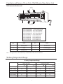
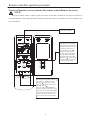
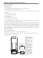
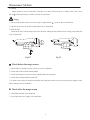
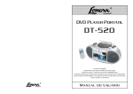
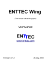
Multi Variable Air Conditioners
Wall Mounted Type Indoor Unit Owner’s Manual
This manual is suitable for the following models:
OV-R22G/NaB-K
OV-R28G/NaB-K
OV-R36G/NaB-K
OV-R45G/NaB-K
OV-R50G/NaB-K
OV-R56G/NaB-K
OV-R22G/NaC-K
OV-R28G/NaC-K
OV-R36G/NaC-K
OV-R45G/NaC-K
OV-R71G/Na-K
OV-R80G/Na-K
OV-R22G/H-K
OV-R28G/H-K
OV-R36G/H-K
OV-R45G/H-K
OV-R50G/H-K
OV-R56G/H-K
OV-R71G/H-K
OV-R80G/H-K
OVL-R22G/NaB-K
OVL-R28G/NaB-K
OVL-R36G/NaB-K
OVL-R45G/NaB-K
OVL-R50G/NaB-K
OVL-R56G/NaB-K
OVL-R22G/NaC-K
OVL-R28G/NaC-K
OVL-R36G/NaC-K
OVL-R45G/NaC-K
OVL-R71G/Na-K
OVL-R80G/Na-K
OVL-R22G/H-K
OVL-R28G/H-K
OVL-R36G/H-K
OVL-R45G/H-K
OVL-R50G/H-K
OVL-R56G/H-K
OVL-R71G/H-K
OVL-R80G/H-K
Please read this manual carefully before operating
Thank you for your selecting of ONIDA airconditioner, please read this usage and
install instruction carefully and keep it well in order to use this unit correctly.
User Notices
1
Safety information
2
The installation of Wall mounted type indoor unit
3
Constitutes and Names of Every Part of Wall Mounted Type Indoor Unit
6
Working Temperature Range
6
Contents
Wired Remote Controller Operation
Procedure
The components of the wired remote control
7
ON/OFF operation
7
Timer setting
8
SLEEP mode setting
9
Swing Control
9
Fan Speed Control
9
Remote controller
operation
procedure
Temp. adjusting
10
Set of running mode
10
Malfunction display
10
Names and functions of every button of the remote control
12
Names and functions of every button of the remote control
(Remove the cover)
13
Operation procedure
14
How to insert batteries
14
The Best Usage Method
15
Maintenance Method
16
Malfunction Analyzing
18
Adjusting Method of Air Direction
19
Function description of functional dial switch S7
19
Model and Technical Parameter
20
USER NOTICES
☆ When operating, the entire capacity of the cooperating indoor unit should be not larger than
that of outdoor unit. Otherwise, it will cause the shortage of cooling (heating) capacity.
☆ A Breaker(or fuse) need to be installed in every indoor unit, and the capacity should in
according with indoor unit’s electrical parameter; all the indoor units are required to be
centralized controlled by a total Switch, this Switch can cut off the electric power supply in
case of emergency. The Breaker(or fuse) on ea ch indoor units have the function of short
circuit prevention and abnormal overload avoiding, it should be connected in normal
situation. The total switch controlling the power supply of all the indoor units. Before
clearing and maintenance job being carried out to the indoor units, it is very important to
turn off the total power supply switch.
☆ In order to turn on the units successfully, the main power switch should be opened 8 hours
before the operation.
☆ After receiving the turn off signal, every indoor unit will continue to work for 20-70sec to
make use of the rest cool air or the rest heat air in the heat exchanger, while preparing for the
next operation. And this is normal.
☆ When the selected operating mode of the indoor unit are clash with the operating mode of the
outdoor unit, the malfunction light will blink after 5s on the indoor unit or remote controller
showing that the operation clash, then the indoor unit will stop. At this time, change the
operation mode of the indoor unit to the one that would not clash with the outdoor operating
mode to make the operation normal. The cooling mode is not clash with the dry mode, while
the fan mode is not clash with any mode.
☆ The appliance shall not be installed in the laundry
☆ An all-pole disconnection switch having a contact separation of at least 3mm in all poles
should be connected in fixed wiring
☆ Missing information regarding electric supply tolerances(+/-10%, +/-1Hz) in documentation
☆ Missing information regarding humidity (30-95%) in documentation
☆ Missing information regarding installation altitude (max 1000m) in documentation
☆ Information regarding transport/storage temperature (-25-55°C) is missing
☆ Main switch provided by end user: main switch handle should be black or gray, it can be
locked in “OFF” position with padlock
☆ The main disconnection device should be explained in user manual and the height should be
recommended at 0.6-1.7m. Over current protection is required (EN 60947-3, EN 60947-2)
☆ The cooling range of the unit is the outdoor environment temp.18-43
DB, the heating range
of the unit( only for the heat pump type unit) is the outdoor environment temp. -16-15
WB.
1
Safety information
1.
Please read this manual carefully before use this unit, and operate it correctly according to the guide in
this manual.
2.
Please take specially note to the meaning of these two marks:
Warning !This mark means that it may cause casualty or badly hurt if the operation is incorrect.
Note!This mark means that it may cause casualty or property loss if the operation is incorrect.
Warning !
● For the usage safety of the air cond itioner, the units should be earthed reliably, and the earth wire should be
connected to the special earth equipment in building. If there is no this kind of equipment, have the units installed by
specialized personnel. Do not connect the earth line with the gas pipe, water pipe, drainage pipe or other places that
specialized personnel considers unsafe.
● Air conditioner must use special power supply circuit and switches for creepage protect and air with enough
capacity should be installed in the circuit.
●
Ensure that the connecting of power cord is normal, otherwise, electric shock or fire may happened.
● Do not cut off the power supply to turn off the unit when it is running, otherwise the useful life of units may
shortened.
● Do not mangle wire or adopts wires that are not re commend to use, otherwise, electric shock or fire may
happened.
●
Please don’t operate the unit by wet hand, or electric shock may happened.
●
Don’t insert finger or stick like things into outlet vent, otherwise, damage may be happened.
● Cut down the main power switch immediately if malfunction (such as smell the burning odor etc.) happen, and
then contact the special engaged maintenance center. If the abnormal state is maintained, the unit may be damaged or
electric shock or fire may be happened.
● Do not refit the conditioner. Please contact the agency or professional personnel to repair or move the
conditioner.
● Do not adopt fuse with unsuitable capacity or adopt iron thread instead of fuse, otherwise malfunction or fire
may happened.
●
Do cut off the main power supply of air conditioner if it would not be used for a long time.
● Please turn off the main power of the unit before cleaning the conditioner, otherwise electric shock or harm may
be happened.
●
Don’t blow the heater otherwise carbon monoxide may be produced for uncompleted burning.
●
Chemical sprayer should be placed 1m or more away from the unit, otherwise fire or explode may be caused.
● Do not let blockage happened in the inlet or outlet vent of the air conditioner, this would cause low efficacy or
unit stop.
2
The installation of Wall mounted type indoor unit
●
Schematic diagram of installation spaces
ceiling
>150
ceiling
>150
>150
wall
>2000
>3000
unit:mm
ground
ground
Important Notice:
● The unit must be installed by the professional personnel according to this install instruction to ensure the well use.
●Please contact the local ONIDA special nominated repair department before installation. Any malfunction caused by
the unit that is installed by the department that is not special nominated by ONIDA would not deal with on time by the
inconvenience of the business contact.
● It should be guide under the professional personnel when the air conditioner unit is moved to other place.
●
The installation of the rear panel
Fig.1
1. Find the horizontal position by seton method; since the drainage pipe is on the left side, adjust the rear panel to
make its left side a little bit lower.
2. Fix the rear panel on the wall by bolt.
3. After installing the rear panel, pull it by hand to check if it is firm enough. The hang panel should support the
weight of an adult (60KG), and the weight shared by every bolt for steady should be fairly even.
4. The diameter showed on the fig.1 is 65mm.
3
Installation the Wall Mounted Type indoor unit
●
Install the piping hole
☆ Make the piping hole (Φ65mm) in the wall at a slight downward slant to the outdoor side. The center of the hole
should be determined refer to Fig.1
☆ Insert the piping-hole sleeve into the hole to prevent the connected piping and wiring from being damaged when
passing through the hole.
● Install the drainage pipe
☆
For well draining, the drain hose should be placed at a
Wrenched
Bent
downward slant.
☆
Do not wrench or bend the drain hose or flood its end by
Flooded
water. (Fig.2)
☆ Wrap heat resistant material when connect the longer drainage
tubethoughindoor.
Fig.2
● Install the connection pipes
Connect the connect pipe with the two relative leading pipe, tie the nut on tie –in of the connect pipe tightly.
Note!
☆ Be careful in bending the connection pipes, or you will damage the pipes.
☆ If the tightening torque is too great in tightening the flare nut, leakage will happen.
● Electrical wiring
Note: The power of every indoor unit should be unity power supply.
1. Open the panel upward;
2. Disassembly the set screw on the connect panel, refer to fig.3;
3. Route the power connection cord from the back and button of the appliance box and though the wiring hole
upward;
4. Wiring the power cord to correspondent terminals via instruction of wiring diagram, which is pasted on the indoor
units. The Yellow-Green cable (i.e. earth wire) should connect to “
” terminal. Use the wire firming slot which
locates in front of wiring row in the electric cabinet to press and firm the connection of power cord, as shown in
fig.4.
Connect pipe
platoon
Wiring cover
Wiring cover
Wiring cover
Wiring cover
Indoor power cord
Fig.4
Fig.3
4
Installation the Wall Mounted Type indoor unit
5. Connect the wiring (communication) through the piping hole of the chassis and the bottom of the appliance upward,
then insert them on the control panel CN15, CN16 and CN17 of the indoor unit, and clamp them with the wire clamp
packed in the chassis;
6. Reinstall the wiring cover on the original place and tighten the bolt;
7. Recover the surface panel.
Note!
● The incorrect of wiring connecting would lead malfunction of some of the electric elements.
● Make sure that the lead between the connect end and the clamp end has some need space after the wire is fixed.
●
Install the indoor unit
1. When routing the piping and wiring from the left or right side of the indoor unit, cut off the tailings from the pipe
holder in necessary (shown in fig.5)
☆ Cut down tailings 1 when only the power cord is led.
☆ Cut down tailings 1,2 (or 1,2,3) when the connection cord and wire are led.
☆ The pad wire type ①、②、③ are recommended.
2. Let the tubing and cord pass though the piping hole after tied up (refer to fig .5 (d)).
3. Hang the claw behind the indoor unit on the pothook on the wall rear panel, move the unit left and right to check if
the body is firm.
4. Guarantee that the install height of the indoor unit should above 2.0m from the floor.
④Left tubing
①Right tubing
②Right rear tubing
(a)
Low material 3
③Left rear tubing
(b)
Connection
pipe
Wrapping tape
Power
connection
cord
Control cord
Low material 2
Low material 1
(c)
Fig.5
5
Drain hose
(d)
Constitutes and Names of Every Part of Wall Mounted Type Indoor Unit
Wall mounted indoor unit
Air in
③
②
①
④
⑤
Air out
OV(L)-R22G/NaB-K
OV(L)-R36G/NaB-K
OV(L)-R50G/NaB-K
OV(L)-R22G/NaC-K
OV(L)-R36G/NaC-K
OV(L)-R71G/Na-K
OV(L)-R22G/H-K
OV(L)-R36G/H-K
OV(L)-R50G/H-K
OV(L)-R71G/H-K
OV(L)-R28G/NaB-K
OV(L)-R45G/NaB-K
OV(L)-R56G/NaB-K
OV(L)-R28G/NaC-K
OV(L)-R45G/NaC-K
OV(L)-R80G/Na-K
OV(L)-R28G/H-K
OV(L)-R45G/H-K
OV(L)-R56G/H-K
OV(L)-R80G/H-K
Name
No.
Name
1
Surface panel
4
Guide louver
2
Filter
5
Connecting pipe
3
Wiring cover
No.
Note:The appearances will be different by the different models of air conditioners.
Working Temperature Range
Working Temperature Range
Indoor side state
Dry bulb temp
Outdoor side state
Wet bulb temp
Dry bulb temp
Wet bulb temp
Rated Cooling
27
19
35
24
Max. cooling
32
23
43
26
Min. cooling
21
15
18
—
Rated Heating
20
15
7
6
Max. heating
27
—
24
18
Min. heating
20
15
-15
-16
6
Wired Remote Controller Operation Procedure
The components of the wired remote control
MODE
FAN
SWING
TIMER
ON/OFF
Fig.1
Every part of wired remote controller
1
Operating mode display (Cool, Dry, Fan, Heat)
9
On/Off button
2
Sleep mode display
10
Timer button
3
Environmental temp.display / Malfunction display
11
Swing button
4
Fan control display (automatic, high, media, low)
12
Swing display
5
Set Temp. display
13
Fan control button
6
Defrosting display
14
Temp. / Timer reducing button
7
Timer display
15
Temp. / Timer rising button
8
Signal receptor
16
Mode button
1) On/Off operation(Fig.2)
●
●
●
Press On/Off button to turn on air conditioner.
Repress On/Off button once to turn off air conditioner.
MODE
Note:The displaying in Fig.2 is the turned off state after connecting with
power supply. After connecting power and normal communication, the
environmental temp. will be displayed on LCD under state of both turned on
FAN
or off. At this time, as shown in Fig.2 there is no pane displayed on LCD,
SWING
which means that the air conditioner is turned off.
TIMER
ON/OFF
Fig2
7
Wired Remote Controller Operation Procedure
2)Timer setting(Fig.3,the following sketch is displayed according
to the functions of wired remote controller)
●
Press TIMER under off state can set On Time; press
MODE
TIMER under on state can set Off Time.
●
Under the circumstance that without setting time ( there isn’t
information in the Timer Time Display Zone), press TIMER, then
the LCD will display the pattern of “
“
xx.x Hours”, and the
FAN
SWING
”and“hours”will keep blinking for 0.5s, press adjusting
button“▲”or
TIMER
can adjust set time. After adjusting set time
by button “▲”or
, repress TIMER once, the pattern“
ON/OFF
”
and “hours” will no longer blinking, which indicates that
Fig3
TIMER had been set.
●
Press TIMER once after electrify, “
0.0 hour” is displayed and both of the two patterns are blinking on LCD,
repress TIMER once again, then the Timer pattern no loner displayed on LCD, which indicated that the
TIMER setting had been cancelled.
●
Under the circumstance of TIMER time had been set ( i.e. the state that "
repress TIMER, then the "
" and " hours" don’t blink),
xx.x hours" will be redisplayed on LCD (note:"xx.x" indicates the set time of last
”and “hours”are blinking, at this time, adjust
time, and will be cancelled after electrify), and both “
“▲”or“ ”to reset timer, or repress TIMER to confirm timer function.
●
The timer of turning on/off ranged from 0.5-24 hours. Every single press of“▲”or
be added or subtracted 0.5 hour. Press“▲”or
serially the set time will add or subtract 0.5 hour
automatically for every 0.5s. The adjusting range of“▲”and
are from 0 to 24, and the mode is
recycling mode.
Button “▲”:
Button
:
0.0
0.0
0.5
0.5
1.0
1.0
, the set time will
······
....
Note:The above displayed is the relative displaying zone.
8
23.5
23.5
24.0
24.0
Wired Remote Controller Operation Procedure
3)SLEEP mode setting (Fig.4)
●
When under the cooling or dehumidifying mode, after
MODE
receiving the SLEEP order for 1 hour, the previous set temp.
Tset will be risen for 1
, and another 1
will be risen after
2 hours that means that the temperature been risen 2
within 2 hours. Then the unit will run according to this set
FAN
temp.
●
SWING
When under the heating mode, after receiving the SLEEP
TIMER
order for 1 hour, the previous set temp. T set will be lower for
, and another 1
ON/OFF
will be lower after 2 hours that means
that the temperature been lowered 2
within 2 hours. Then
Fig4
the unit will run according to this set temp.
●
There is no SLEEP mode under fan mode.
Note:The wired remote controller has no SLEEP mode button; if
SLEEP mode is needed to be set, complete the procedure by
wireless remote controller.
4)
●
●
MODE
Swing Control(Fig.5)
FAN
Press Swing button then the swing mode will be operated
SWING
by the air conditioner.
TIMER
Repress Swing button once to stop swing mode.
ON/OFF
Note: There is no swing mode for duct type indoor unit
Fig5
5)Fan Speed Control(Fig.6)
●
Every press of the fan speed button, the fan speed will be changed
according to the following order:
Auto
●
Low
Medium
High
MODE
Under dehumidifying mode : Fan speed will be set to low
FAN
automatically.
SWING
TIMER
ON/OFF
Fig6
9
Wired Remote Controller Operation Procedure
6)Temp. adjusting (Fig.7)
●
Under the state without time setting, press“▲”and
to
MODE
adjust temp..
▲:To rise set temp.;
To reduce set temp.
(every press of this button, temp. will be risen or subtracted
FAN
for 1
●
SWING
Temp. adjusting ranged from 16
30
under any running
TIMER
mode.
ON/OFF
7)Set of running mode(Fig.8)
●
Every once press of the mode key, the running mode would be
Fig7
changed according to the following order:
COOL
DRY
FAN
HEAT
MODE
●
Under cooling mode, the display of cooling will on, and the
set temp. should be lower than the present room temp. If the
set temp. is higher than the present room temp., air
FAN
conditioner would not enter cooling mode.
●
SWING
Under dehumidify mode, display of dehumidify will on.
Fan will run in low speed in certain temp. range. The
TIMER
dehumidifying effect of this mode is better than that of
ON/OFF
cooling mode, and saves more energy.
●
Under heating mode, the display of heating will on. The set
Fig8
temperature should be higher than that of present room; if the
set temp. was lower than that of present room, heating mode
would not be operated.
●
MODE
Under fan mode, the display of fan will on.
8)Malfunction display(Fig.9)
●
When malfunction happened in running, malfunction code
FAN
will be showed in environmental temp. display zone. Fig.9
SWING
indicates that the compressor is operating high pressure
TIMER
protect.
●
When malfunction happened, except fan mode will still work
ON/OFF
in normal, outdoor unit and fan will close under mode of
cooling, dehumidify and heating, but LCD display will not be
affected.
10
Fig9
Wired Remote Controller Operation Procedure
●
When controller displaying malfunction, please turn off the unit to stop
displaying and has it repaired by specialized personnel.
The meaning of malfunction code is as following:
Malfunction code
Malfunction
E1
High pressure protection of compressor
E2
Indoor anti-frozen protection
E3
Low pressure protection of compressor
E4
Discharge temp. protection of compressor
E5
Compressor overload protection
E6
Transmit malfunction
E7
Modes conflict
F0
Indoor environment temp. sensor malfunction
F1
Indoor pan tube inlet tube temp. sensor malfunction
F2
Indoor pan tube middle temp. sensor malfunction
F3
Indoor pane tube outlet tube temp. sensor malfunction
F4
Outdoor environment temp. sensor malfunction
F5
Outdoor pan tube inlet tube temp. sensor malfunction
F6
Outdoor pan tube middle temp. sensor malfunction
F7
Outdoor pan tube outlet tube temp. sensor malfunction
F8
Discharge temp. sensor 1 (rated frequency) malfunction
F9
Discharge temp. sensor 2 (digital) malfunction
FA
Greasy temp. sensor 1 (rated frequency) malfunction
Fb
Greasy temp. sensor 2 (digital) malfunction
Fc
High pressure sensor malfunction
Fd
Low pressure sensor malfunction
11
Remote controller operation procedure
Names and functions of every button of the remote control
NOTE!
●
Make sure that there is no obstruction between the remote control and the signal receptor.
● The remote control signal can be received at the distance of up to about 10m.
● Don’t drop or throw the remote control.
● Don’t let any liquid flow into the remote control.
● Don’t put the remote control directly under the sunlight or any place where is very hot.
SWING button
the guide louver swings
according to certain
angle when press once;
repress once to stop
operating.
FAN button
Press the button to
change the speed of the
fan according to the
following order.
SWING
FAN
AUTOFAN
TEMP. button
Set temp. increases 1 c
by pressing "+" and
decreases 1 c by pressing
"-" once.
Set temp. : 16 c~30 c
Set temp. : 16 c~30 c
AUTO FAN
SPEED
OPER
AUTO
AIR
SWINGHUMIDLIGHT SAVE
TIMER
ONOFF
HR.
COOL
DRY
FAN
HEAT
Set temp. : 16 c~30 c
Set temp. : 16 c~30 c
on/off button
Press the button to turn on
the unit. Press the button
once again to turn off the
unit and cancal the timer.
MODE button
Press the button to change
the mode according to the
following order
MODE
ON/OFF
NOTE: The cooling only
units have no
mode.
NOTE!
After every indoor unit received the turn off signal, the fan and electric inflate valve will continue to work for
20-70mins to make use of the rest cool or rest heat, while for preparation for the next work. And this is normal
phenomenon.
12
Remote controller operation procedure
Names and functions of every button of the remote control (Remove the cover)
NOTE!
This type of remote control is a kind of general use remote control that is suitable for several types (function) of
air conditioner units. Please understand that the functions and buttons that are not suitable for this air conditioner will
not be introduced.
Liquid crystal displayer
It shows all set contents.
SWING
FAN
AUTOFAN
SLEEP button
Press the button to set SLEEP
mode, and stop when repressed.
When the sleep mode is in the
cool and dry mode, the set
temp. will increases 1~2
during the set time, then the
unit will operate according to
the temp.. When sleep mode is
in the heat mode, the set temp.
decreases 1~2
during the set
time, then the unit will operate
according to the set temp..
OPER
AUTO
AIR
SWING HUMID
LIGHT SAVE
TIMER
ONOFF
HR.
SLEEP
AIR
LIGHT
HUMID
TIMER ONTIMER OFF ANION
SAVE
MODE ON/OFF
Temp./Timer button
When the unit is operating, increase 1
by pressing "+" button once, and
decrease 1 by pressing "-" button
once. The indoor temp. can be set in
the range of 16-30 .
Press the "Timer OFF/TIMER ON"
button at operating/ stopping to set the
off/on time. Press "Timer OFF/TIMER
ON" once to increase 0.5 hour for the
set time. The longest set time is 24
hours; repress it once to cancel timer.
13
Remote controller operation procedure
Operation procedure
Normal procedure
1. Press on/off button after connected with the power, and then the unit is operating.
2. Press MODE button to choose the need operation mode.
3. Press button SWING to make the guide louver swings according to certain angle when press once; repress once to
stop operating.
4. Press FAN button to set the fan speed.
5. Press +/- button to set the need temp.
Selectable procedure
6. Press SLEEP mode to set the sleep state.
7. Press TIMER OFF button to set the set time.
8. Repress on/off turn off indoor air conditioner. Under cooling and dehumidify mode, rest cool air will be blow for
20~70s; Rest heat air will be blow for 60s under heating mode.
Note: When the operating mode selected by the indoor unit is clash with the one selected by the outdoor unit,
the remote controller will display the operating clash after 5 seconds and the power light will flicker, then the
indoor unit turns off. At this time, the units will become normal after the operating mode of the indoor unit is
changed to cooperate with the outdoor unit. Cool mode can cooperate with dry mode, and fan mode can
cooperate with any mode.
How to insert batteries
Two batteries (Two AAA dry-cell batteries) are used by the remote control
1. Remote the cover from the back of the remote control downward, take out the worn batteries and insert two new
ones (Make sure the two poles are correct)
2. Re-attach the cover.
ACL
1.All the prints and code no. will
be showed on the displayer
after the insert of batteries. The
remote control can be operated
after 10sec.
2.The lifetime of the batteries is
about one year.
3.Don't confuse the new and
worn or different types of
batteries.
①Remove the cover
4.Remove batteries when the
③Re-attach the cover remote control is not in use for
a longtime to avoid malfunction
caused by liquid leakage.
5.The remote control should be
open
placed about 1m or more from
the TV set or any other electric
appliances.
6.The remote control should be
RESET KEY
used in the receivable range
(the reception range is 10m)
7.When the remote control can
not be controlled in the
situation of inserted batteries,
please remove the back cover
②Insert two AAA dry-cell and press "ACL" button to
make it normal.
battaries(attachment)
14
The Best Usage Method
Adjust to proper indoor
temperature; too cool of
indoor temperature is not
good for health.
Clean filter
thoroughly
Take out the batteries
when the air
conditioner won't be
used for a long time
Prevent direct burn
of sunlight and
leakage of cooled air
●
The best usage method
● Adjust set temp. in proper to prevent electricity wasting. It is better to adjust indoor temp. 5
or less higher or
lower than outdoor temperature.
● The better effect will be maintained by adjusting guide louver swings downward when heating and swing in
horizontal direction when cooling.
● When air conditioner is running, don’t open indoor windows or doors for long, otherwise the efficacy of unit will
be lowered.
●
Prevent cooled air swing to body directly for long time and making indoor temp. too low, for it is bad for health.
●
Do not pour water to unit or clean it by water, otherwise malfunction or electric shock may happened.
● Do not mangle power cord and signal control wire; If power cord and signal control wire of the air conditioner
are damaged, do change it by special cord or wire.
● This air conditioner allows voltage fluctuate within 220±10%V.
● This air conditioner cannot used for drying clothes and refrigerating food, etc..
15
Maintenance Method
Warning!
!
● Do turn off the unit and cut off the main power supply when cleaning the air conditioner, otherwise electric shock
may happened.
● Do not make the air conditioner wet or electric shock may be lead; Ensure that the air conditioner will not be
cleaned by water rinsing under any circumstance.
● Volatility liquid like thinner or gasoline would damage the appearance of air conditioner. (So, only soft dry cloth
and wet cloth moistened by neutral cleaning fluid could be used to clean the surface panel of air conditioner.)
●
Cleaning panel
Note!Do take down it before cleaning.
1. Pull along the direction of arrows to take down the panel.
2. Clean
Clean it by pubescence brush, water and neutral cleaning fluid, then throw water or dry it.
Note!
Do not use water above 45
to wash the panel to prevent fade or deformation.
3. Install panel
As shown in Fig.II, install the stands of both ends of panel into slot and put the middle rotating shaft into the
groove, then cover the panel and clasp according to the arrow direction.
Fig.I
●
Fig.II
Cleaning the air filters
☆ Clean it once about 3 months; When the usage environment has lots of dust, it should be cleaned more frequently.
1. Take down the air filter
As shown in Fig.III, open the surface panel by holding the both ends of groove by the arrow direction, then take
the air filter out downward.
16
Maintenance Method
2. Cleaning
Adopts cleaner or water to wash filter; if the filter is too dirty ( like oil stain on it ), adopts warm water ( lower
than 45
) with neutral scourer to clean it, then dry it in the shade.
Note!
☆ Do not clean the filter by hot water whose temp. is higher than 45
to prevent fade or deformation.
☆ Do not burn it on fire or the filter would catches fire or deformation.
3. Install air filter
Install the air filter well according to the arrow direction, making the side marked “Front” facing yourself and then
cover the panel well.
Fig.III
Fig.IV
● Check before the usage season
☆ Check if there is blockage in inlet or outlet vent of air conditioner.
☆ Check if the earth wire had earthed reliably.
☆ Check if the batteries in wireless remote controller had been exchanged.
☆ Check if the air filter had been install well.
☆ In order to start up the air conditioner smoothly after long time’s turned off, turn on the main power supply 8 hours
before turning on the air conditioner.
●
Check after the usage season
☆ Clean filter and body of air conditioner.
☆ Cut off the main power supply of air conditioner.
17
Malfunction Analyzing
Warning!
Do not repair air conditioner by yourself for the incorrect repair would lead electric shock or fire. Please
contact service center and had the unit repaired by specialized personnel. Check the following item before
contacting to repair could save your time and cost.
Malfunction Phenomena
Malfunction Analyzing
The air conditioner can’t start up just after turned off
The over load protect switch of the unit makes it runs after
3 mins delay
Odor gave out when the unit just turned on
This is because when air conditioning, odors or cigarette
smoke from the room that was sucked in is discharged
again.
Slight bicker was heard when the unit is running
This is the sound for inner refrigerant flowing
Mist come from air outlet vent when cooling
Indoor air is cooled rapidly
Creak sound is heard when running or after run
The grating sound caused by expands of panel and other
parts for the change of temperature.
The air conditioner cannot run
Is power cut?
Is the power supply connected?
Is the circuit protector started aside?
Is the voltage too high or too low?
If TIMER had been set in wireless remote controller?
The cooling (heating) effect of the air conditioner is
not good
Is the temp. set in proper?
Is the inlet, outlet vent of outdoor unit blocked?
Is the air filter too dirty to cause blockage?
Are windows and doors closed?
Is air quantity set to Low speed?
Is there other heating resource in room?
Under the circumstance of changed batteries, the wireless
remote controller sometimes would appear the phenomena
of couldn’t control. Take out the back cover and
press ”ACL” button to make it normal.
Wireless remote controller cannot control
The air conditioner is under abnormal disturbance or
changing function too frequently, to make wireless remote
controller cannot control. Cut off main power switch and
re-electrify could resume normal operation.
Is the controller within the receiving area?Or is there
blockage?
Check if the voltages of batteries in wireless remote
controller are enough; Otherwise change the batteries.
18
Malfunction Analyzing
● service center
When the following phenomena appeared, please stop operating immediately, cut off main power supply of unit and
contact service center for the conditioner.
☆ Harsh sound heard when running;
☆ The fuse or protector cut frequently;
☆ Substance or water pulled in the unit involuntary;
☆ Water leakage in room;
☆ Over heat of power cord;
☆ Odor is given out when running;
●
After-sales Service
☆ When having quality or other problems when purchasing air conditioner, please contact the local service center.
Adjusting Method of Air Direction
●
Adjusting air direction up and down
☆ Control guide louver motor by wireless remote controller could make guide louver swings with rotating up and
down, or makes the guide louver stop at a certain angle to have air supplied.
☆ Press SWING button on wireless remote controller to make guide louver swing with rotating up and down;
Repress once to stop the operation.
●
Adjusting air direction left and right
☆ Move the horizontal louver left and right could adjust left and right direction of air outlet, or adjust the air outlet to
reach every corner of the room by 3 different outlet direction to make indoor temp. more even.
Function description of functional dial switch S7
1. The 3-bit dial switch must be set before energizing the main board and it determines running state of
indoor unit.
2. Function of it is as follow:
Dial switch
Silk screen
Function
1(S / R)
Selection of memory mode:
A、Election between reset mode and standby mode after
energizing;
B、This function is available without wired controller.
2(L / I)
Selection between manual controller and receiver:
A、If manual controller is selected, remote-control function of
receiver will be shielded;
B、If receiver is selected, wired controller will be non-effective.
3(M / S)
Setting of main and slave indoor units:
A、For resolution of conflict among the modes;
B、This function is available without wired controller.
19
Dial ON
Dial OFF
Standby after
energizing
Reset after
energizing
Selecting wired
controller
Selecting
receiver joint
Main indoor unit
Slave indoor unit
Model and Technical Parameter
●Parameter of wall mounted type indoor unit
Model
OV(L)-R22G/NaB-K
OV(L )-R28G/NaB-K
OV(L)-R36G/NaB-K
Cooling Capacity
kW
2.2
2.8
3.6
Heating Capacity
kW
2.5
3.2
4.0
Air volume
3
m /h
360
360
500
Noise(H/L)
dB(A)
37/28
37/28
43/28
220-240V~ 50Hz
220-240V~ 50Hz
220-240V~ 50Hz
0.032
0.032
0.048
Φ9.52
Φ9.52
Φ12.7
Φ6.35
Φ6.35
Φ6.35
Flare Connection
Flare Connection
Flare Connection
φ20×1.5
φ20×1.5
φ20×1.5
770×190×250
770×190×250
830×189×285
Power Supply
Fan Motor
Input
kW
Gas Pipe
mm
Connection
Liquid
mm
Pipe
Pipe
Connecting Method
Drain pipe
mm
(Outter Dia.×Thickness)
Outline Dimension
mm
(W×D×H)
Model
OV(L)-R45G/NaB-K
OV(L)-R50G/NaB-K
OV(L)-R56G/NaB-K
Cooling Capacity
kW
4.5
5.0
5.6
Heating Capacity
kW
5.0
5.8
6.3
Air volume
3
m /h
500
700
750
Noise(H/L)
dB(A)
43/28
45/40
45/40
220-240V~ 50Hz
220-240V~ 50Hz
220-240V~ 50Hz
Power Supply
Fan Motor
Connection
Pipe
Input
kW
0.048
0.056
0.058
Gas Pipe
mm
Φ12.7
Φ12.7
Φ15.9
Liquid
Pipe
mm
Φ6.35
Φ6.35
Φ9.52
Flare Connection
Flare Connection
Flare Connection
Connecting Method
Drain pipe
(Outter Dia.×Thickness)
mm
φ20×1.5
φ30×1.5
φ30×1.5
Outline Dimension
(W×D×H)
mm
830×189×285
1020×228×310
1020×228×310
20
Model and Technical Parameter
Cooling Capacity
kW
OV(L)R22G/NaC-K
2.2
Heating Capacity
kW
2.5
3.2
4.0
5.0
Air volume
3
m /h
360
360
500
500
Noise(H/L)
dB(A)
37/28
37/28
43/28
43/28
220-240V~ 50Hz
220-240V~ 50Hz
220-240V~ 50Hz
220-240V~ 50Hz
0.032
0.032
0.048
0.048
Φ9.52
Φ9.52
Φ12.7
Φ12.7
Φ6.35
Φ6.35
Φ6.35
Φ6.35
Flare Connection
Flare Connection
Flare Connection
Flare Connection
φ20×1.5
φ20×1.5
φ20×1.5
φ20×1.5
770×190×250
770×190×250
830×189×285
830×189×285
Model
Power Supply
Fan Motor
Input
kW
Gas Pipe
mm
Liquid
mm
Pipe
Connecting Method
Drain pipe
mm
(Outter Dia.×Thickness)
Outline Dimension
mm
(W×D×H)
Connection
Pipe
Model
OV(L)R28G/NaC-K
2.8
OV(L)R36G/NaC-K
3.6
OV(L)R45G/NaC-K
4.5
OV(L)-R71G/Na-K
OV(L)-R80G/Na-K
Cooling Capacity
kW
7.1
8.0
Heating Capacity
kW
8.0
9.0
Air volume
3
m /h
1200
1200
Noise(H/L)
dB(A)
49/42
49/42
220-240V~ 50Hz
220-240V~ 50Hz
Power Supply
Fan Motor
Connection Pipe
Input
kW
0.063
0.085
Gas Pipe
mm
Φ15.9
Φ15.9
Liquid Pipe
mm
Φ9.52
Φ9.52
Flare Connection
Flare Connection
φ30×1.5
φ30×1.5
1178 ×227×326
1178 ×227×326
Connecting Method
Drain pipe
mm
(Outter Dia.×Thickness)
Outline Dimension
(W×D×H)
mm
21
Model and Technical Parameter
Cooling Capacity
kW
OV(L)R22G/H-K
2.2
Heating Capacity
kW
2.5
3.2
4.0
5.0
Air volume
3
m /h
360
360
500
500
Noise(H/L)
dB(A)
37/28
37/28
43/32
43/32
220-240V~ 50Hz
220-240V~ 50Hz
220-240V~ 50Hz
220-240V~ 50Hz
0.032
0.032
0.048
0.048
Φ9.52
Φ9.52
Φ12.7
Φ12.7
Φ6.35
Φ6.35
Φ6.35
Φ9.52
Flare Connection
Flare Connection
Flare Connection
Flare Connection
φ20×1.5
φ20×1.5
φ20×1.5
φ20×1.5
770×190×250
770×190×250
830×189×285
830×189×285
OV(L)R56G/H-K
5.6
OV(L)R71G/H-K
7.1
OV(L)R80G/H-K
8
Model
Power Supply
Fan Motor
Input
kW
Gas Pipe
mm
Liquid
mm
Pipe
Connecting Method
Drain pipe
mm
(Outter Dia.×Thickness)
Outline Dimension
mm
(W×D×H)
Connection
Pipe
OV(L)R28G/H-K
2.8
OV(L)R36G/H-K
3.6
OV(L)R45G/H-K
4.5
Cooling Capacity
kW
OV(L)R50G/H-K
5
Heating Capacity
kW
5.8
6.3
8
9
Air volume
3
m /h
700
750
1200
1200
Noise(H/L)
dB(A)
45/40
45/40
49/42
49/42
220-240V~ 50Hz
220-240V~ 50Hz
220-240V~ 50Hz
220-240V~ 50Hz
0.056
0.058
0.063
0.085
Φ12.7
Φ15.9
Φ15.9
Φ15.9
Φ9.52
Φ9.52
Φ9.52
Φ9.52
Flare Connection
Flare Connection
Flare Connection
Flare Connection
φ30×1.5
φ30×1.5
φ30×1.5
φ30×1.5
1020×228×310
1020×228×310
1178 ×227×326
1178 ×227×326
Model
Power Supply
Fan Motor
Input
kW
Gas Pipe
mm
Connection
Liquid
mm
Pipe
Pipe
Connecting Method
Drain pipe
mm
(Outter Dia.×Thickness)
Outline Dimension
mm
(W×D×H)
☆ If the parameter changed, refer to the data offered on nameplate.
22