1
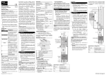
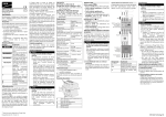
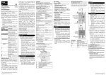
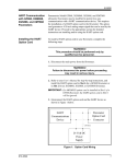
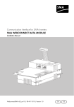
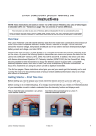
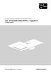
SMA Energy Meter
Installation Manual
EN
251851.0100
Validity
This document is valid for the
SMA Energy Meter* (EMETER-10.GR1)
from firmware version 1.02.04.R.
Target Group
Only qualified persons with the following skills
are allowed to perform the tasks described in this
document:
• Training in the installation and commissioning
of electrical devices
• Training in electrical hazards and local safety
regulations
• Knowledge of all applicable standards and
directives
• Knowledge of and compliance with this document and all safety precautions
Symbols Used
Symbol
☐
☑
✖
Explanation
Indicates a hazardous situation which, if not avoided,
will result in death or serious injury
Indicates a hazardous situation which, if not avoided,
can result in death or serious injury
Indicates a hazardous situation which, if not avoided,
can result in minor or moderate injury
Indicates a situation which,
if not avoided, can result in
property damage
Information that is important for a specific topic or
goal, but is not safety-relevant
Indicates a requirement for
meeting a specific goal
Desired result
A problem that might occur
Intended Use
The Energy Meter is a measuring device which
detects electrical measured values at the connection point and makes them available via Speedwire.
The Energy Meter is for private use only.
This product is NOT an energy meter for the consumption of active power as defined in the EU Directive 2004/22/EC (MID). The Energy Meter
must not be used for billing purposes. The data
collected by the Energy Meter relating to the
power generated by your PV system may deviate from the data of the main Energy Meter.
The Energy Meter must only be connected to the
subdistribution of the household on the load side
behind the Energy Meter of the electric utility
company. For applications > 63 A, current transformers must be connected to the Energy Meter.
The Energy Meter is designed for indoor use only.
The Energy Meter is approved for use in all EU
member states. Only use the Energy Meter in accordance with the information provided in the enclosed documentation. Any other use can result
in personal injury or property damage.
For safety reasons, it is not permitted to modify
the product or install components that are not explicitly recommended or distributed by SMA Solar Technology AG for this product. Any use of
the product other than described in the Intended
Use section does not qualify as appropriate usage. It is prohibited to make any modifications
that are not approved by SMA.
The enclosed documentation is an integral part
of the product and must be read and observed.
Keep in a convenient place for future reference.
Supported Products
For information on the supported products, see
the product page of the Energy Meter at
www.SMA-Solar.com.
Safety Precautions
DANGER
Danger to life due to electric shock
Lethal voltages are present in the live
components.
• Only use the Energy Meter in a dry environment and keep it away from liquids.
• Install the Energy Meter in the switch
cabinet only and ensure that the connection areas for the line conductors and
the neutral conductor are behind a cover or have contact protection.
• Disconnect the Energy Meter from
voltage sources before cleaning. The
Energy Meter must be cleaned with a
dry cloth only.
• Observe the prescribed minimum clearance between the network cable and
live installation components, or use suitable insulation.
Technical Data
Communication
Nominal voltage
Frequency
Self-consumption
Limiting current/line conductor
Connection cross-section
with current transformers
Speedwire
230 V/400 V AC
50 Hz/60 Hz ± 5%
2W
63 A
See recommendations of the current
transformer manufacturer
Connection cross-section 10 mm2 to 25 mm2
without current transformers
Torque for screw termi- 2 Nm
nals
Weight
0,30 kg
Dimensions (W / H / D) 70 mm x 88 mm x
65 mm
Ambient temperature in − 25°C to +40°C
operation
Ambient temperature dur- − 25°C to +70°C
ing transport/storage
Relative air humidity*
5% to 95%
Protection class
none
Degree of protection** IP2X
* non-condensing
** in accordance with IEC 60529
• Flashing green: Energy Meter is sending or
receiving data.
Information on Connection and Commissioning
The line conductor L1 supplies the Energy Meter
with power. At least the line conductor L1 and
the neutral conductor must be connected for the
Energy Meter to switch on.
DANGER
Danger to life due to electric shock if
external disconnect switch is missing
Lethal voltages are present in the live components of the Energy Meter.
• Install an external disconnect switch between the Energy Meter and the gridconnection point. The external disconnector must be close to the
Energy Meter and easily accessible.
Complete Multicast support required
Incomplete Multicast support of individual
network components can lead to malfunction
of the Energy Meter.
Electrical Connection for Applications
< 63 A
The following figure shows a connection example. For exact connection specifications, contact
your electric utility company.
Scope of Delivery
• 1 x Energy Meter (EMETER-10.GR1)
• 1 x installation manual
Contact your distributor if the scope of delivery is
incomplete or damaged.
Product Description
NOTICE
Damage to or destruction of the
Energy Meter if connected to ISDN
• Do not connect an ISDN cable to the network terminal of the Energy Meter.
Damage to or destruction of the
Energy Meter due to inappropriate use
• The Energy Meter must not be operated
beyond the values specified in the technical
data.
A
B
C
D
E
Connection area for line conductors
and neutral conductor
Network terminal (Speedwire)
Reset button
Speedwire LED
Status LED
LED States
Status LED (
):
• Glowing green:
Energy Meter is switched on.
• Flashing green slowly:
Energy Meter starting up.
• Flashing green fast:
firmware update running.
• Glowing or flashing red or orange:
an error has occurred. Refer to Section "Troubleshooting".
Speedwire LED (
):
• Off: no Speedwire connection established
• Glowing green: Speedwire connection established.
DANGER
Danger to life due to electric shock
Lethal voltages are present in the switch
cabinet.
• Disconnect the connection point from
voltage sources and make sure it cannot
be reconnected.
• Ensure that the conductors to be connected to the Energy Meter are free of
voltage.
Designation
L1, L2, L3
N
OUT
IN
The following figure shows a connection example. For exact connection specifications, contact
your electric utility company.
WARNING
Fire hazard
If a fuse is missing or incorrect and a fault
occurs, a fire may be caused. This can result
in death or serious injury.
• Protect the line conductors of the
Energy Meter with a fuse or a main/
selective circuit breaker, max. 63 A.
1. Mount the Energy Meter on the top-hat rail.
Hook the Energy Meter into the top edge of
the top-hat rail and press down until it snaps
into place.
2. Connect the conductors to the Energy Meter.
Observe the permitted connection cross-section and torque for screw terminals (see Section "Technical Data"):
• In a three-phase utility grid, connect the
line conductors L1, L2 and L3 and the
neutral conductor to the Energy Meter in
accordance with the wiring diagram.
• In a single-phase utility grid, connect the
line conductor L1 and the neutral
conductor to the Energy Meter in
accordance with the wiring diagram.
Electrical Connection for Applications
> 63 A
Additionally required material (not included in the scope of delivery):
☐ 3 x current transformer
☐ Connection cables for current transformers
Recommendations for the current transformer
SMA Solar Technology AG recommends current transformers designed for a secondary
current of 5 A. The current transformers
should have at least accuracy class 1.
WARNING
Danger to life due to electric shock
If network cables are laid outdoors, they
may be subject to overvoltages, e.g. due to
flash of lightning. This can result in death or
serious injury.
• Network cables laid outdoors must be
suitably protected from overvoltage.
Procedure:
Designation
L1, L2, L3
N
OUT
IN
Explanation
Line conductor
Neutral conductor
Meter output, load side
Meter input, grid side
Explanation
Line conductor
Neutral conductor
Meter output, load side
Meter input, grid side
* referred to in this document as Energy Meter
EnergyMeter-IA-en-16 | Version 1.6
SMA Solar Technology AG
Procedure:
DANGER
Danger to life due to electric shock
Lethal voltages are present in the subdistribution of the household.
• Disconnect the connection point from
voltage sources and make sure it cannot
be reconnected.
• Ensure that the conductors to be connected to the meter are free of voltage.
WARNING
Fire hazard
If a fuse is missing or incorrect and a fault
occurs, a fire may be caused. This can result
in death or serious injury.
• Protect the line conductors of the
Energy Meter with a fuse or a main/selective circuit breaker switch, max. 63 A.
1. Connect one current transformer to each line
conductor L1, L2 and L3.
2. On each current transformer, connect one
connection cable for current measurement to
each of the secondary current terminals
(k/S1 and l/S2). Observe the permitted connection cross-section of the Energy Meter (see
Section "Technical Data"):
3. Connect the connection cables for current
measurement to the Energy Meter. Observe
the prescribed torque for screw terminals (see
Section "Technical Data"):
4. Connect the connection cables for voltage
measurement to the Energy Meter. Observe
the prescribed torque for screw terminals (see
Section "Technical Data"):
5. Connect the connection cables for voltage
measurement to the corresponding line conductors.
Network Terminal
IGMP protocol from version 2 must be
supported
The Energy Meter works with Multicasts. For
the correct function of the Energy Meter, all
network devices used must support the IGMP
protocol, minimum required version 2
(IGMP V2).
Additionally required material (not included in the scope of delivery):
☐ 1 x network cable
Recommended cable types:
• SF/UTP, S-FTP, S/UTP, SF/FTP, S/FTP, S-STP
For further information on cable types, refer to
the Technical Information "SMA Speedwire
Fieldbus" at www.SMA-Solar.com.
Procedure:
1. Connect the network cable to the network terminal (Speedwire) of the Energy Meter.
2. Connect the other end of the network cable to
a router/network switch. SMA products
which are to receive measured values must be
integrated in the same local network.
EnergyMeter-IA-en-16
Commissioning
1. Cover the Energy Meter with the cover or the
contact protection of the subdistribution.
2. Switch the power supply to the subdistribution
back on.
☑ The LEDs of the Energy Meter glow during
start-up. If there is only one Energy Meter in
the system, the Energy Meter connects
automatically to SMA communication
products in the same local network. For more
information on commissioning, see the user
manual of the supported devices.
✖ The LEDs are not glowing or the
Energy Meter is not displayed by the SMA
communication products?
• Correct the error (see Section "Troubleshooting").
Resetting the Energy Meter to
Default Settings
Procedure:
• Press the reset button with a sharp object and
hold it for two to six seconds.
Restarting the Energy Meter
Procedure:
• Press the reset button with a sharp object and
hold it for six seconds or longer.
Accessing the User Interface
Procedure:
1. Call up the Internet browser and in the address line enter
http://energymeter“Serial number“.local,
e.g.:
http://energymeter7435667356.local
Note: The serial number can be found on the
type label of the Energy Meter.
2. Press Enter.
☑ The user interface of the Energy Meter opens.
✖ The user interface does not open?
• Correct the error (see Section "Troubleshooting").
Configuring the Current Transformer
Procedure:
1. Open the user interface of the Energy Meter
(see Section "Accessing the User Interface")
2. On the homepage, select Device settings >
Current Transformer settings.
3. Activate the checkbox
Use Current Transformers.
4. Enter the required transformation ratio in the
field Current Transformer ratio.
5. Select [Apply].
.Performing
a Firmware Update
Procedure:
1. Download the update file from
www.SMA-Solar.com and save it to your
computer.
2. Open the user interface of the Energy Meter
(see Section "Accessing the User Interface")
3. Follow the instructions in the menu
Firmware update.
Procedure after Replacing an
Energy Meter
Procedure:
• If more than one Energy Meter is installed in
your system and you have replaced one or
more Energy Meters, you will need to adjust
the serial number of the corresponding
Energy Meter in the Sunny Island/Sunny Boy
Smart Energy. This will avoid inaccurate meter reading data in the Speedwire data module Sunny Island/Sunny Boy Smart Energy:
– In systems without Sunny Home Manager,
enter the serial number of the
Energy Meter via Sunny Explorer in the
Sunny Island/Sunny Boy Smart Energy
(for information on changing device parameters, see user manual of the Sunny Explorer).
– In systems with Sunny Home Manager,
configure
the
Energy Meter
in
Sunny Portal (see user manual of the
Sunny Home Manager).
Troubleshooting
The status LEDs are off.
The Energy Meter is not supplied with power.
• Make sure that at least the line conductor L1
and the neutral conductor are connected to
the Energy Meter.
The status LEDs are glowing or flashing red
or orange.
An error has occurred.
• Restart the Energy Meter (see Section "Restarting the Energy Meter").
• Contact the SMA Service Line.
The Speedwire LEDs are not glowing.
or
The Energy Meter is not displayed by the
SMA communication product.
The network cable has not been correctly connected to the network terminal.
• Make sure that the network cable is correctly
connected to the network terminal.
The Energy Meter is not integrated into the same
local network as the SMA communication product.
• Connect the Energy Meter to the same router/network switch as the SMA communication product.
The Energy Meter provides unrealistic measured values.
The Energy Meter has been installed the wrong
way round.
• Connect and commission again.
The user interface cannot be called up via
http://energymeter“Serial number“.local.
The name resolution via Avahi (Multicast DNS) is
not working.
• Call up the user interface via the current IP address of the Energy Meter. Call up the user interface of the router and read off the IP
address of the Energy Meter (see router manual).
• With Windows XP/7/8:
Install Apple Bonjour® (download links at
www.apple.com. Note: Apple Bonjour® is
also contained in Apple iTunes®.).
• Contact your network administrator.
Disposal
Procedure:
• Dispose of the Energy Meter in accordance
with the locally applicable disposal regulations for electronic waste.
Open Source Licenses
The license text and corresponding information is
displayed in the user interface of the
Energy Meter. You can request the source code
with modifications from the SMA Service Line.
Contact
If you have technical problems concerning our
products, contact the SMA Service Line. We require the following information in order to provide you with the necessary assistance:
• Type and serial number of the Energy Meter
(see type label of the Energy Meter)
• Type and serial number of the SMA products
(e.g. Sunny Home Manager, Sunny Explorer,
Sunny Island)
• Error description
SMA Solar Technology AG
Niestetal
International SMA Service Line
Toll free worldwide:
00800 SMA SERVICE
(+800 762 7378423)
www.SMA-Solar.com
© 2004 to 2014 SMA Solar Technology AG.
All rights reserved.
SMA Solar Technology AG