1
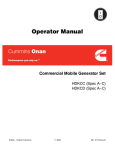
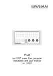
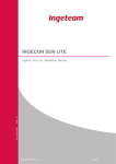
Installation Manual Ingecon® Sun Three-Phase Inverter INGECON SUN SMART AAS2000I KI 02 Rev._ Ingecon Sun Three-Phase Inverter – Installation Manual Ref.: AAS2000IKI02 Rev.:_ Dec-2009 Ingeteam Energy S.A. Pg. 1 de 40 12/2009 Installation Manual Ingecon® Sun Three-Phase Inverter Ingecon® Sun Three-Phase Inverter – Installation Manual Note: Because of the continuous evolution of its products, Ingeteam Energy S.A. reserves the right to update and modify this manual without prior notice. Table of Contents Page 1. Introduction............................................................................................5 1.1 General Remarks on Safety.................................................................................5 1.2 Description of the Activities on the Device............................................................7 2. Assembly................................................................................................8 2.1 Delivery and Unpacking........................................................................................8 2.2 Location................................................................................................................9 2.3 Disposal.............................................................................................................. 11 3. Electrical Connection...........................................................................12 3.1 Opening the equipment and access...................................................................13 3.2 Earth Fault Contact / Grid Connection Indicator.................................................14 3.3 Access to Auxiliary Connections.........................................................................14 3.4 GSM / GPRS - Modem communication connection............................................15 3.5 RS-485 line - Communication connection..........................................................15 3.6 Ethernet - Communication connection................................................................15 3.7 Optical Fibre - Communication connection.........................................................15 3.8 Ground connections............................................................................................15 3.9 Connection to the Power Grid.............................................................................16 3.10 Connection to the PV array.................................................................................17 3.11 Prior to start up...................................................................................................18 3.12 Hermetic seal......................................................................................................18 4. Start-up................................................................................................19 4.1 Equipment checking...........................................................................................19 4.1.1 Inspection...........................................................................................................................19 4.2.1 4.2.2 Adjusting the settings............................................................................................20 Starting up.............................................................................................................20 4.2 Power up.............................................................................................................20 Pg. 2 de 40 Ref.: AAS2000IKI02 Rev.:_ Dec-2009 Installation Manual Ingecon® Sun Three-Phase Inverter 5. Uninstalling the inverter........................................................................21 6. Preventive Maintenance.......................................................................23 6.1 Maintenance Procedures....................................................................................23 7. Using the display and keyboard...........................................................25 7.1 7.2 7.3 7.4 7.5 7.6 7.7 Keyboard............................................................................................................25 Display................................................................................................................26 Main Menu..........................................................................................................27 Monitoring...........................................................................................................27 Stop reasons.......................................................................................................30 Adjustments........................................................................................................31 Inverter data........................................................................................................31 8. Troubleshooting....................................................................................32 8.1 LED indications...................................................................................................32 8.1.1 Green LED............................................................................................................32 8.1.2 Orange LED..........................................................................................................33 8.1.3 Green LED............................................................................................................33 8.1.1.1 Flashing slowly.................................................................................................................32 8.1.1.2 Flashing quickly................................................................................................................32 8.1.1.3 LED remains on...............................................................................................................32 8.1.2.1 Flashing quickly................................................................................................................33 8.2 8.3 8.4 8.5 8.6 8.7 8.1.3.1 LED remains on...............................................................................................................33 List of the Alarms and shutdown reasons...........................................................35 Inverter alarms caused by protections................................................................36 Disconnection from the Grid...............................................................................36 Replacement of the ‘Electronics Block’...............................................................37 Replacement of the Control Board.....................................................................38 Replacement of Varistors in the Measure Boards..............................................38 Ref.: AAS2000IKI02 Rev.:_ Dec-2009 Pg. 3 de 40 Installation Manual Ingecon® Sun Three-Phase Inverter documentation related to this manual CATALOGUES Ingecon® Sun Commercial Catalogue PC00ISA03 MANUALS Ingecon® Sun Single-Phase Installation Manual Ingecon® Sun IP20 Three-Phase Inverter Installation Manual Ingecon® Sun Three-Phase IP54 Installation Manual AAP2000IKR01 AAS2000IKR01 AAS2000IKR03 Ingecon® Sun Hybrid Single-Phase Installation Manual Ingecon® Sun Hybrid Three-Phase Installation Manual Communication Accessories Installation Manual AAR2000IKR01 AAR2000IKR01 AAX2002IKR01 Ingecon® Sun SinglePhase Operation Manual Ingecon® Sun Three-Phase IP20 Operation Manual Ingecon® Sun Three-Phase IP54 Operation Manual AAP2000IKT01 AAS2000IKT01 AAS2000IKT03 Monitoring Software Operation Manual Ingecon® Sun Hybrid Monitor Operation Manual Ingecon® Sun Hybrid Single-Phase Operation Manual AAP2005IKT01 AAR2005IKT01 AAR2000IKT01 Ingecon® Sun Hybrid Three-Phase Operation Manual Ingecon® Sun Manager Operation Manual Ingecon® Sun String Control Installation Manual AAR2000IKT02 AAX2005IKT01 AAS2002IKR01 Ingecon® Sun ThreePhase + 100 kW Installation Manual AAV2000IKR01 Pg. 4 de 40 Ref.: AAS2000IKI02 Rev.:_ Dec-2009 Installation Manual Ingecon® Sun Three-Phase Inverter 1. Introduction Carefully read this manual and carry out the installation in conformity with the instructions provided. 1.1 General Remarks on Safety Attenzione. Non aprire. Solo personale autorizzato. Caution. Do not open. Only authorized operators The operations described in this manual must be performed exclusively by duly qualified operators, especially trained to work on electrical installations and having a suitable knowledge of this manual and of the wiring diagrams attached to the switchboard (hereafter the ‘qualified personnel’). Risk of electric shock! The system voltage is not automatically switched off upon the opening of the compartment coverings. Therefore, only qualified personnel is authorised to access those areas following the safety provisions described in this manual. The safety provisions described herein represent the minimum level of protection to be ensured. For a higher safety level we recommend to disconnect the main power supply and to test for the absence of voltage. The system may be subject to unexpected current returns. Risk of electric shock! Beside the safety provisions described in this manual, the user must also comply with all the applicable regulations related to the type of plant, Country, etc. Please make sure that the company charged of the installation carries out the work only with qualified personnel. Per qualsiasi intervento sul dispositivo, l’impianto deve essere disinserito dalla tensione. The system must be disconnected from the power supply any time it is necessary to work on the device. Ref.: AAS2000IKI02 Rev.:_ Dec-2009 Pg. 5 de 40 Installation Manual Ingecon® Sun Three-Phase Inverter In order to provide a minimum level of safety, the operators must always comply with the ‘5 golden rules’: 1. Disconnect the power supply 2. Make sure the system cannot be powered on unexpectedly 3. Test for absence of voltage 4. Earth and short-circuit the system 5. Protect yourself against any energised device in close proximity and mark the working area with safety panels, if necessary. Before these operations have been carried out, the system is to be considered as energised and nobody should be allowed to work on it. To test for absence of voltage it is compulsory to use measuring instruments of Class III - 1,000 Volt. Ingeteam Energy, S.A. cannot be held responsible for any damage arising from any improper use of its products. Pg. 6 de 40 Ref.: AAS2000IKI02 Rev.:_ Dec-2009 Installation Manual Ingecon® Sun Three-Phase Inverter 1.2 Description of the Activities on the Device INSPECTION: This kind of intervention involves opening the covering to carry out a visual inspection. MANOEUVRE: Any activity related to software loading, testing of the warming/cooling systems and corrective maintenance on the system (except on the switchboards) carried out by means of the operator-machine interface. MANIPULATION: Any activity of assembly and/or replacement of components, as well as any change to the calibration settings of the protection devices. The following provisions must be considered when performing an activity of inspection, manoeuvre or manipulation: The Ingecon® Sun devices can be opened exclusively by authorised personnel during installation and tuning operations. A serious risk of electric shock exists even after the device has been disconnected from the electric grid and photovoltaic panels. Wait at least 10 minutes to allow the system to discharge its natural capacitance. The use of the following Personal Protection Equipment (PPE) is compulsory: - Dielectric gloves compliant with the system’s voltage. - Gloves for protection against mechanical hazards. - Approved safety goggles for protection against electrical hazards. - Safety shoes. Never touch the radiator located behind the system’s Electronic Block, since it may reach extremely high temperatures. When handling the device, remember that: It is forbidden to handle the device when a source of power supply is still connected to the system. Always carry out a test to ensure that there are no electric contacts between the grid or any of the photovoltaic panels and a component of the device. Always wear safety gloves. Ref.: AAS2000IKI02 Rev.:_ Dec-2009 Pg. 7 de 40 Installation Manual Ingecon® Sun Three-Phase Inverter 2 Assembly General Provisions: The Ingecon® Sun Inverter must be installed by qualified personnel only, in conformity with the general provisions on safety described herein. The Inverter works under currents and voltages that may be dangerous to the operators. In case of high level of humidity or excess of condensation water inside the device, dry it carefully before carrying out any electric connection. 2.1 Delivery and Unpacking Delivery Upon delivery of the device, check the details on the delivery note, fill out the RECIPIENT SIGNATURE field and return it to the sender’s address. The following table shows the specifications of the packing pallets: MODEL PALET TYPE WEIGHT (Kg) HEIGHT/WIDTH/LENGTH (mm) 20 kW , 25 kW y 30 kW Wooden:Bubble wrap and wooden box 340 1300 / 750 / 600 Device handling The following provisions strictly apply to any handling operation of the device outside the factory premises. In case of non-compliance with these provisions, the warranty may become null and void without any responsibility of INGETEAM. The Inverter must be placed VERTICALLY, even in case it is necessary to return it to the factory. Avoid collisions and brisk movements. Use a fork lift to transport the device. Follow the basic provisions below: 1. Unscrew the front and rear covers of the base (never unscrew the side ones). 2. Insert the forks at their maximum width under the cabinet. 3. Insert the forks until they come out the opposite side of the cabinet, so as to ensure the stability of the device. Pg. 8 de 40 4. Make sure the forks are correctly levelled to prevent the device from tilting. 5. After placing the device in its definitive position, re-install the base covers. Ref.: AAS2000IKI02 Rev.:_ Dec-2009 Installation Manual Ingecon® Sun Three-Phase Inverter IIdentifying the equipment The serial number clearly identifies the inverter. All communications with Ingeteam S.A. should indicate this number.. Avda. Ciudad de la Innovación, 13 31621 Sarriguren (Navarra) ESPAÑA [email protected] Tel 948 288000 Fax 948 288001 Ingecon®Sun 25 IP 54 Pac: 25 Kw Udc: Uac: 3 X 400 Vac Fac: S/N 011070411C88 2009 405 - 900 Vdc 50 Hz 015070411C88 Std: Serial number Damage during transport Should the equipment sustain damage during transport: 1) Do not install it 2) Immediately notify your distributor of this situation within a 5 day period from the reception date. Should it be necessary to finally return the equipment to the manufacturer, the original packing should be used. Separate packing waste All packing waste can be given to an Authorised Manager for not-dangerous disposal. Anyway, each part of the packing will be: Wood (box, palets, corners): Authorised Manager for not-dangerous disposal.. Plastics (bag and bubble wrap): Adequated Collection Service container Cardboard: Adequated Collection Service container. 2.2 Location Dust free air must be provided in the enviroment of the equipment. Adequqted air quality, temperature and humidity will be asured. Leave at least 20 cm of clear space around the equipment to allow the free circulation of air. The Ingecon® Sun Three-phase inverters are equipped with fans. These fans will rotate for a few seconds when the grid connection is made. This routine offers a simple means of allowing the installer to check the fan operation. It is forbidden to leave any object on the equipment Locate the equipment in a particle free environment to prevent the ingress of particles through the vents. Ref.: AAS2000IKI02 Rev.:_ Dec-2009 Pg. 9 de 40 Installation Manual Ingecon® Sun Three-Phase Inverter Facilitate the circulation of incoming air through the vents and through the lower pit, if present, and also the outgoing air through the upper vents. Avoid corrosive enviroments. Due to its considerable weight, the equipment needs to be positioned on a firm and completely horizontal floor. If the equipment is seated over a pit to house the cabling conduits, then the equipment base must rest on the largest possible area of firm flooring without creating any mechanical stress in the equipment structure. The inverter should be located in an environment with an ambient temperature of between -10 to 45ºC. The equipment is designed for maximum performance in these temperature conditions. At higher temperatures the equipment will limit its power output. During operation, the inverter will make a slight buzzing noise. Do not locate the inverter in an occupied room or on supports that could amplify this buzzing noise. Install the equipment in a place that is easily accessible for installation and maintenance work and which offers sufficient space for personnel to operate the keypad, read the display and access the inverter interior. Anchoring Ingecon® Sun Three-phase inverters can be equipped with an optional sujection system. This system consist on metal plates that are screwed to the four corners of the plinth and to the concrete slab where the inverter is located. In following picture, shape and way of installation of this plates in the enclosures of 10 to 15 kW. Pg. 10 de 40 Ref.: AAS2000IKI02 Rev.:_ Dec-2009 Installation Manual Ingecon® Sun Three-Phase Inverter Following screwing prescriptions are mandatory: - Minimun distance between the center of thedrill on the concrete slab to its borders of 72 mm. - Diameter of the drill on the concrete slab to its borders of 8 mm. - Minimun depth of thedrill on the concrete slab of 65 mm. - Minimun thickness of the concrete slab of 100 mm. - Torque of 20 Nm. - Minimun depth of the screw of 45 mm. 45 mm. 65 mm. 72 mm. 100 mm. 2.3 Disposal At the end of the useful life of the equipment, the waste must be given to an Authorised Manager for disposal. Ref.: AAS2000IKI02 Rev.:_ Dec-2009 Pg. 11 de 40 Installation Manual Ingecon® Sun Three-Phase Inverter 3. Electrical connection Once the equipment has been mounted in its definitive location, the electrical connections can be made to the auxiliary equipment, the Power Grid and the PV array. The Ingecon® Sun inverter electrical connection must be made by qualified personnel, observing the general safety conditions set out in this manual. The inverter operates under hazardous voltages and currents. The basic inverter connections should be made in the following order: Connection of the insulation failure detection switch (optional) Connection of any auxiliary equipment (optional) Communication line (optional). Earth connection. See the «Earth connections» section. Inverter connection to the Power Grid. See the «Power grid connection» section. Contactor Inverter - L1 L2 L3 N DC voltage surge arresters (OPTIONAL) Pg. 12 de 40 Fuses Transformer 50 / 60 Hz DC Breaker (OPTIONAL) 3 X 400 Vac + + + + + + filter PV Input Connection to the PV array. See the «PV array connection» section. AC voltage surge arresters (OPTIONAL) Ref.: AAS2000IKI02 Rev.:_ Dec-2009 Installation Manual Ingecon® Sun Three-Phase Inverter 3.1 Opening the equipment and access Before opening the front door, make absolutely certain that there are no live voltages inside the cabinet. For this, the equipment needs to be disconnected from the PV array and from the power grid. LIkewise, it is essential to close the equipment before connecting it to the PV array or power grid. For Inspection, Operation or Manipulation tasks: Make an electrical check to ensure that no part of the equipment is in electrical contact with either the grid or any of the PV panels. The use of safety gloves and glasses homologued for electrical risk is compulsory to ensure lack of voltage. After disconnecting the equipment from the PV array and power grid, wait at least 10 minutes before opening the door. Due to its internal capacitance, the inverter may maintain hazardous voltage levels. Whilst the panels are receiving light, the DC cables may be under hazardouse voltage levels. Inverter access All the cables access the unit through the PG cable glands located in the cabinet base as indicated in the following drawings. If quick connectors option is chosen, they are located on the base too. Wire description in following table: Description Diameter Number of holes INPUT DC 32 2 Wire section 11-21 INPUT DC C.R. 12.5 28 PV quick connector Type3 or Type 4 OUTPUT AC 1 25 4 9 - 17 OUTPUT AC 2 40 1 19 - 28 GROUNDING 25 1 9 - 17 base view Ref.: AAS2000IKI02 Rev.:_ Dec-2009 Pg. 13 de 40 Installation Manual Ingecon® Sun Three-Phase Inverter 3.2 Earth Fault Contact / Grid Connection Indicator The inverter is equipped with a normally-open potential-free contact, which can perform one of the following two functions: Insulation failure detection in the DC circuit. - contact open: no insulation failure in the DC circuit - contact closed: insulation failure in the DC circuit Indicator to show that the unit is connected to the power grid by means of its internal contactor. - Contact open: the internal grid connection contactor is open, the inverter is not connected to the power grid. - Contact closed: the internal grid connection contactor is closed, the inverter is connected to the power grid. The equipment always takes measure of the Earth Fault although the contact is used in Grid connection indicator function. The equipment is factory configured to perform one or other function; the function option must be expressly requested when the order is sent to Ingeteam Energy S.A. The normally open contact admits a voltage of 230 Vac and a maximum current of 10 A. The contact is accessed through the cabinet side PGs. N.O. X1.1 3.3 X1.2 Access to the auxiliary connections In some PV installations the inverter needs to be connected to auxiliary equipment such as solar radiation sensors, thermal sensors, anemometers, etc. Consult the communication accessory installation manual «AAX2002IKI01 Communication accessories Installation Manual.» For enhanced operation, the cables transporting these auxiliary signals should be kept at a distance from the power cables. In these models the auxiliary signals are directly connected to the analogue input card «AAP0016 Tarjeta de Entradas Analógicas». Consult the communication accessory installation manual Communication accessories Installation Manual.» Pg. 14 de 40 «AAX2002IKI01 Ref.: AAS2000IKI02 Rev.:_ Dec-2009 Installation Manual Ingecon® Sun Three-Phase Inverter 3.4 GSM / GPRS - Modem communication connection At the installer’s request, optionally, the inverters may incorporate hardware to enable a GMS / GPRS communication link to be established with the inverter. Consult the communication accessory installation manual «AAX2002IKI01 Communication accessories Installation Manual.» 3.5 RS-485 line- Communication connection At the installer’s request, optionally, the inverters may incorporate hardware to enable communication through an RS-485 serial line. In all these units, the auxiliary signals are directly connected to card «AAP0022 Com RS-485» Consult the communication accessory installation manual «AAX2002IKI01 Communication accessories Installation Manual.» 3.6 Ethernet- Communication connection At the installer’s request, optionally, the inverters may incorporate hardware to enable communication through Ethernet. Consult the communication accessory installation manual «AAX2002IKI01 Communication accessories Installation Manual.» 3.7 Optical Fibre - Communication connection Upon the installer’s request and as an option, a hardware component for communication via optical fibre can be installed on the Inverter. On all these devices, the auxiliary signals are connected directly to the ‘AAP0009 fibre optics’ board. 3.8 Ground connections The metal parts of the inverter (equipment ground) are electrically connected to the ground plate located on the lower right side of the equipment. To guarantee personal safety, this point must be connected to the installation ground bar. Grounding Ref.: AAS2000IKI02 Rev.:_ Dec-2009 Pg. 15 de 40 Installation Manual Ingecon® Sun Three-Phase Inverter 3.9 Connection to the Power Grid The ports for the Power grid connection cables are located either on the cabinet side or base. If the distance between the inverter and the Grid connection point requires the use of a greater cable section, then the use of an external distribution box, located close to the inverter, is compulsory in order to change from one section to another. The cable section shall always be based on the equipment power rating. The inverter protections at the grid connection support a short-circuit current of up to 70 kAmp. Prior to any manipulation, check that there is no electrical hazard at the power input from the grid. The use of safety gloves and glasses homologued for electrical risk is compulsory to ensure lack of voltage. These models are equipped with a three terminal bi-metal connector (three phases with neutral) for connection to the power grid. The maximum permitted section for these terminals is 50 mm2 each phase. Pg. 16 de 40 Ref.: AAS2000IKI02 Rev.:_ Dec-2009 Installation Manual Ingecon® Sun Three-Phase Inverter 3.10 Connection to the PV array The cables connecting the equipment to the PV array access the unit through the PG cable glands located on the cabinet sides or base. Prior to any manipulation, always check to ensure there is no electrical hazard at the PV array voltage input. Never forget that any incident light on the panels generates voltage at the panel terminals. Therefore the inverter interior may hold voltages of up to 900 volts even when not connected to the Grid. The use of safety gloves and glasses homologued for electrical risk is compulsory to ensure lack of voltage. Caution: Connect the positive pole of the string of panels to the terminals marked +, and the negative pole to the terminals marked -. If the distance between the inverter and the PV array connection point requires the use of a greater cable section, then the use of an external distribution box, located close to the inverter, is compulsory in order to change from one section to another. The connection of these models to the PV array is made through 2 terminals with a maximum section of 50 mm2 . This type of connection ensures that the installer makes a safe disconnection between the inverter and PV array. If the installer decides to take the option of including quick connectors, there will be 14 pairs of terminals for push-in cables located on the base of the enclosure of the equipment. When the option is ordered, it has to be especify what type, type 3 or type 4 quick connectors are required. If the installer decides to take the PV array directly to this terminal strip (without using quick connectors) it is highly recommended to install a prior breaker element. Ref.: AAS2000IKI02 Rev.:_ Dec-2009 Pg. 17 de 40 Installation Manual Ingecon® Sun Three-Phase Inverter 3.11 Prior to start up The INGECON SUN SMART inverters are equipped with a series of MT breakers that protect different parts of the unit. Before the installation can be started up, these breakers need to be closed. Prior to manipulating the MT breakers in any way, first check that there are no electrical hazards in the unit interior. The use of safety gloves and glasses homologued for electrical risk is compulsory to ensure lack of voltage. Make sure that Q1, Q2 and Q3 MT breakers are in ON position: 3.12 Hermetic seal During installation, it is important to ensure that the unit’s IP rating is maintained. For all connections through the PG cable glands, allow sufficient cable length inside the equipment to ensure that there is no pull on the electric terminals inside. Check that any unused ports are hermetically sealed. Safety measures The front door should be only opened after disconnecting the inverter from the grid and PV array. Likewise, it is essential to close the unit before connecting it to the PV array or grid. If thre is no alarms, after the waiting time, the inverter will begin magnetizing the transformer producing a soft buzzing. Then, it will connect the grid and search the MPPT. Pg. 18 de 40 Ref.: AAS2000IKI02 Rev.:_ Dec-2009 Installation Manual Ingecon® Sun Three-Phase Inverter 4. Start up The inverter may only be started up once all the connections indicated in the previous section have been made and once the unit has been perfectly sealed. 4.1 Equipment checking The INGECON SUN SMART elements are protected by MT brakers. Make sure they are closed prior to start up. Prior to any manipulation on MT breakers, check there is not electrical hazard. To check that no voltage is present, it is mandatory to use: class III - 1000 Volt testing devices, and recommended protection equipment. 4.1.1 Inspection Prior to the inverter power-up, a general inspection of the equipment should be made, primarily consisting in: · Cabling inspection: - Check that there are no loose cables - Check that the cables are in good condition and that there are no nearby hazards which could lead to the deterioration of the cables, such as intense heat sources, sharp objects or devices which could impact against or pull on the cables. - Check that all protection devices are in ON position. - If AC surge arresters has been ordered, make sure they are correctly inserted on their base, and that their status indicator is not red.. It’s forbiden remove methacrylate protections to make this inspection. · DC module: If DC surge arresters option has been chosen, make sure they are correctly inserted on their bases and their status indicator is not red. · Electronic block module: - Check that MT breakers are closed. - Check that DC fuses are correctly installed. · AC module: Las comprobaciones a realizar en el módulo de salida AC son las siguientes: - Check that MT breakers are closed. - Check that AC fuses are correctly inserted on their bases. - If AC surge arresters has been ordered, make sure they are correctly inserted on their base, and that their status indicator is not red. Ref.: AAS2000IKI02 Rev.:_ Dec-2009 Pg. 19 de 40 Installation Manual Ingecon® Sun Three-Phase Inverter 4.2 Power up Once you have made a general visual inspection, checked the cabling and ensured that the unit is sealed correctly, you can then proceed to power up the equipment, whilst maintaining it in the stop position. Follow the guidelines set out in the equipment-specific instruction manual. When performing the tasks indicated in this point, it is mandatory to ensure that the equipment is sealed, thereby avoiding any possible contacts with live parts without IP5X protection. 4.2.1 Adjusting the settings Check that the equipments starts up. Red LED remains on because Manual Stop is activated. Check that the values of AC and DC voltages in Monitoring menu. They should be: 340V ≤ Vac1, Vac2, Vac3 ≤ 440V 400 ≤ Vdc ≤ 900 Vdc shows the value of DC actual voltage. Pressing OK while selecting this value it is able to see the Positive PV array Voltage (PPV) and the Negative PV array Voltage to Earth (NPV) to check that PV array is correctly balanced, and it don’t has any earth fault contact. Check there is not any alarm apart of Manual Stop: Alarm 1000H. 4.2.2 Starting up Once described actions have been completed, proceed to start up the equipment. - Change to Start Inverter from the display and keyboard. Red LED will switch off, and green LED will begin flash. - After one minute, the circuit will be connected authomatically, and the fans will start up for a few seconds. Green LED will remain on, and when checking the alarms, there won’t be any of them, showing 0000H, that means there is no alarm. Pg. 20 de 40 Ref.: AAS2000IKI02 Rev.:_ Dec-2009 Installation Manual Ingecon® Sun Three-Phase Inverter 5. Uninstalling the inverter To uninstall the inverter, proceed as follows: - Disconnect the unit from the power grid, the PV array and the back-up power sources. - Wait 10 minutes for the internal capacitance to discharge. - Open the unit and check that no voltage is present.. - Disconnect the cables as follows: - The insulation failure detector switch. - Auxiliary equipment (analogue inputs, etc...). - Communications line. - the connection to the Power Grid. See the section on «Connection to the Power Grid» - the connection to the PV array. See the section on «Connection to the PV array» - earth connection. See the section on «earth connections». Pay particular heed to the following warning note: Make an electrical check to ensure that there is no electrical contact whatsoever between either the grid or the PV panels and any part of the equipment. Remember that personal protective equipment (PPE) is compulsory: to verify that no voltage is present. And remember: The Ingecon® Sun units may only be opened by qualified personnel. During the installation, adjustment and maintenance operations, it is compulsory to use personal protective equipment (PPE): safety helmet, glasses, gloces and footwear. - Dielectric glasses appropiate for work voltages. - Safety glasses against mechanical risk damage. - Safety glasses homologued for electrical risk. - Safety footwear - Helmet Do not touch the radiator located behind the electronics block, it can reach high temperatures. Any installation work requiring the unit to be opened must be performed in a dry atmosphere, to prevent the ingress of moisture that could condensate and damage the electronics. Ingeteam Energy S.A. will assume no liability for damages caused by the improper use of its equipment. Ref.: AAS2000IKI02 Rev.:_ Dec-2009 Pg. 21 de 40 Installation Manual Ingecon® Sun Three-Phase Inverter Disposal At the end of the useful life of the equipment, the waste must be given to an Authorised Manager for disposal. The «User Manual» provides the Authorised Manager with information on the location of the components to be decontaminated. INGETEAM ENERGY S.A. don’t accept responsability of hazard produced by a inappropiate use of the devices. Any change in the device have to be previously suggested to INGETEAM. Applicable Enviromental Legislation compliance will be watched in the practice of our work, customer requirements included. Special attention will be paid to the handle of dangerous products, and the correct separation the disposal. Pg. 22 de 40 Ref.: AAS2000IKI02 Rev.:_ Dec-2009 Installation Manual Ingecon® Sun Three-Phase Inverter 6. Preventive Maintenance Recommended Preventive Maintenance Tasks will be done ONCE A YEAR. All Maintenance Procedures should be should only be carried out by suitable qualified personnel. There is a serious electrical discharge hazard. The set of conditions detailed in Chapter1 should be considered to acess to compartment enclosures. All Maintenance Checks and Procedures should be done with the INVERTER WITHOUT VOLTAGE following all manipulation safety conditions. 6.1 Maintenance Procedures. Check enclosure state. It is necessary a visual checking to verify the state of enclosures, doors and handles, IP54 door seals, and the anchorage of the inverter to their screws both top screw and bottom screw if available. It´s also necessary to check if there are dents, scratchs and rust that will damage the cabinet IP protection. If this type of defects appear, damaged pieces should be replaced. Check cables and terminals state. - Check the correct lay-out of the cablesavoiding the contact with live parts. - Check defects in isolations and hot points, verifying isolation and terminal colors. State of the tighten of screws of plates and cables of power Proceed to review the tighten of screws aplying the strength according to the following table: M8 24 Nm M10 47 Nm M12 64 Nm According to DIN 13. Check visually that the conection platesof AC output maintain security distance and their original electrical properties. Check humidity inside the cabinet. If there is humidity, it is compulsory drying it until connecting. Check the correct anchorage of the components of the cabinet to their screws. Ref.: AAS2000IKI02 Rev.:_ Dec-2009 Pg. 23 de 40 Installation Manual Ingecon® Sun Three-Phase Inverter Check the correct ventilation of the equipment: Check the state of the ventilator filters; Proceed to clean and replace it if necessary. Extract the filter removing previously the ventilation grid. Beat softly the filter to separete particles fixed on the filter. Use vacuum cleaner or similar. If the filter continues dirty, clean it in water at 40ºC. If the filter is oily or greasy, replace with a new one. Check the state of the air extraction ventilator; Proceed to clean and replace it if necessary. Clean radiator´s fins. Clean ventilation grids. The inverters make a slight buzzing noise. Check surrorroundings properties in order to avoid amplifying the buzzing. Install the inverters in an easily accesible place so there is enough room for carrying out installation and maintenance procedures and it is easy to use the keyboard, read the Display and open the inverter. Pg. 24 de 40 Ref.: AAS2000IKI02 Rev.:_ Dec-2009 Installation Manual Ingecon® Sun Three-Phase Inverter 7. Using the Screen and Keyboard The Ingecon® Sun inverters are equiped with a «Screen + Keyboard» unit for user and installer - machine communications. This interface displays the principal internal parameters and allows the entire system to be adjusted during installation. ESC OK The parameters, variables and commands are organised into menus and submenus. 7.1 Keyboard ESC The keyboard comprises the following four keys: Esc. Press to exit the parameter editor mode without making changes, to exit a menu and return to an upper level in the structure, when you do not want to confirm a change or accept a proposed value. Up. This key serves to scroll up a list of parameters or files within the same level, or increase the value of an editable parameter by one basic unit. Down. This key serves to scroll down a list of parameters or files within the same level, or decrease the value of an editable parameter by one basic unit. OK OK. Serves to validate a parameter change, to access a lower level menu, to confirm a change or accept a proposed value. Above the keyboard there are three LEDs: Green Led. Slow flickering: Waiting becouse of low radiation Status. Fast Flickering: Start-up Status. Continous light: Inverter connected. Orange Led. Fast Flickering: Alarm that don’t cause the stop of the inverter. Red Led. Continous light: Alarm that causes inverter stop. Ref.: AAS2000IKI02 Rev.:_ Dec-2009 Pg. 25 de 40 Installation Manual Ingecon® Sun Three-Phase Inverter 7.2 Display The display consists on: Upper line, where current time and date appear. Internal clock adjust Summer / Winter time authomatically. Central zone, where are shown instantaneous values of PV Array Voltage, Power injected by the inverter, and Output Voltages. Lower line, where appear the functions that the different keys have in the current screen. 12:00 12/04/09 NODO 1 99,2 KW 673V ALRM STOP 229 V 229 V 229 V MENU If the inverter is manually stopped, instead the injected power, a text with “STOPPED” will be shown. Key functios at initial screen are: Start Inverter / Stop Inverter. Enter to Main Menu. If an alarm is present in the inverter, there will be a flashing message of: ALRM on the lower left corner, and then the ESC key will serve to show the alarms in the equipment. For example: 12:00 12/04/09 FRECUENCY ALARM VOLTAGE ALARM MANUAL STOP ALARM Press ESC to quit this screen. para salir de esta pantalla, volver a pulsar Pg. 26 de 40 ESC . Ref.: AAS2000IKI02 Rev.:_ Dec-2009 Installation Manual Ingecon® Sun Three-Phase Inverter 7.3 Main menu Main menu has four submenus: MONITORING. Main parameters and internal variables are shown here. This data inform about the Status of the equipment. STOP REASONS. Five last Stop Reasons are shown here. AJUSTSMENTS: All adjustsments of the inverter are shown here. INVERTER DATA. Inverter data are shown here. 12:00 09/01/09 MAIN PRINCIPAL MONITORING STOP REASONS ADJUSTSMENTS INVERTER DATA 7.4 Monitoring Access by pressing OK once selected MONITORING. 12:00 09/01/09 MAIN PRINCIPAL MONITORING STOP REASONS ADJUSTSMENTS INVERTER DATA Listed below is a description of the variables in each particular screen: Screen 1. Pac: Power the inverter is delivering to the Power Grid in kW. Pdc: Power provided by the solar panels in kW. Etot: Total energy in kWh delivered by the inverter to the Grid since it left the factory. The recording of the serial number on the unit marks the start of this power record. E.Par: Total energy in kWh delivered by the inverter to the Grid since last time generated power record was set to zero. Ref.: AAS2000IKI02 Rev.:_ Dec-2009 Pg. 27 de 40 Installation Manual Ingecon® Sun Three-Phase Inverter Screen 2. Vdc: Voltage provided by the solar panels to the inverter in Volts. Vac1: Inverter output voltage for Power Grid phase 1 in volts. Vac2: Inverter output voltage for Power Grid phase 2 in volts. Vac3: Inverter output voltage for Power Grid phase 3 in volts. Screen 3. Idc: Current provided by the solar panels in Amps. Iac1: Output current for Grid phase 1 in Amps. Iac2: Output current for Grid phase 2 in Amps. Iac3: Output current for Grid phase 3 in Amps. Screen 4. Frec1: Output frequency in phase 1. Frec2: Output frequency in phase 2. Frec3: Output frequency in phase 3. Cos.Phi: Cosine of phi. This is the cosine of the phase angle existing between the grid voltage and the current delivered by the inverter Screen 5. Rpv: Impedance between PV array and Ground. Rpv+: Impedance between + pole of PV array and Ground. Rpv-: Impedance between - pole of PV array and Ground. Screen 6. Alarms: 0000H, 0001H, 0002H, 0004H, 0008H, 0010H, 0020H, 0040H, 0080H, 0100H, 0200H, 0400H, 0800H, 1000H, 2000H, 4000H, 8000H, Pg. 28 de 40 Current inverter alarm status. Everything is operating correctly. Grid frequency is out of range Grid voltage is out of range Current PI saturation (internal alarm) Unexpected reset (internal alarm) Continuous over-current at the output (Internal alarm) Temperature, power electronics AD converter reading (inverter internal alarm) Instantaneous overcurrent at the output (Internal alarm) AC circuit protections DC circuit protections DC circuit insulation failure Failure in power electronic Alarm due to a manual stop Alarm caused by a configuration change Overvoltage at the input from the panels Voltage very low at the input from the panels Ref.: AAS2000IKI02 Rev.:_ Dec-2009 Installation Manual Ingecon® Sun Three-Phase Inverter Alarmas Hist: From the«Alarma Inv» menu, pressing provides access to the submenu «Hist.Alarm», which shows the history of all alarms that have been activated since the inverter was last connected to the grid. TempInt: Inverter Power Electronics Temperature. TempCI: Inverter Control Electronics Temperature. Screen 7. N.Conex: The number of connections to the Grid made throughout all the operating hours. N.ConexPar: Número de conexiones a red efectuadas desde el último reseteo del contador. T.Conex: T.ConexPar: The number of connections to the Grid made since last RESET. Ref.: AAS2000IKI02 Rev.:_ Dec-2009 Es el número de horas que el inversor ha estado conectado a red. Pg. 29 de 40 Installation Manual Ingecon® Sun Three-Phase Inverter 7.5 STOP REASONS In this menu you can see the list of the last five reasons for an inverter shutdown, and time and date of each one. 12:00 09/01/09 STOP REASONS 13:43 17:30 17:37 17:22 13:15 (08/01) (07/01) (06/01) (05/01) (05/01) -> -> -> -> -> MANUAL STOP POW CONSUMPTION POW CONSUMPTION POW CONSUMPTION FREC Shutdown reasons: SR VDC High input voltage at the panels. SR FREC Incorrect grid frequency SR VAC Incorrect grid voltage SR VARISTORS Failures in the AC surge arresters SR INS. FAILURE DC isolation failure SR CURRENT RMS Overcurrent maintained at AC output SR TEMPERATUREPower electronics overheating SR CONFIG Stoppage due to a configuration change SR MANUAL STOP Manual stoppage SR MIN VPV Low input voltage at the panels. SR HW_DESCX2 Hardware failure (internal) SR FAULT (1) Power electronics failure SR FAULT (2 Power electronics failure SR FAULT (3) Power electronics failure SR CURR.PEAK Instantaneous overcurrent at AC output SR FIRMWARE.CH Stoppage due to a firmware change SR ADC READING AD converter reading failure (internal) SR LOW POWER Insufficient solar radiation SR DC.PROT DC protection SR AUX.TEMP Printed circuit overheating SR AC PROT AC protection SR AC MAG PROT Error at the AC magnetic breaker SR CONTACTOR Error when closing the contactor SR WD RESET Soppage due to Watch Dog reset (internal). SR ADC LAT AD converter error (internal). SR FATAL ERROR Power electronics fatal error SR CURR PI SAT Current PI saturation (internal). Pg. 30 de 40 Ref.: AAS2000IKI02 Rev.:_ Dec-2009 Installation Manual Ingecon® Sun Three-Phase Inverter 7.6 AJUSTMENTS Date and Date The current time and date can be changed from this menu. The internal clock automatically makes the time change from summer / winter. Change Inverter Number In this menu is assigned the number of the inverter in the installation. It’s neccessary to configure the communications. Language Here you can select the language of the display. Grid Quality Grid Quality parameters can be changed here. Security Code will be neccessary. Grounding PV array grounding type can be modificated here. Security Code will be neccessary. Connexion Tipe The time that waits the inverter to connect to the grid can be modified here.Security Code will be neccessary. Total Reset This option resets all partial counters. Security Code will be neccessary.. 7.7 INVERTER DATA Inverter data are shown in this screen: 12:00 09/01/09 INVERTER DATA NS: Firm: 011090102R34 AAS1040_P FirmDis: BootDis: AAS1091_ AAS1092_ Serial Number (SN) Number that identifies the inverter. Firmware Version (Firm) Name and Version of the Firmware of the inverter. Display Firmware Version (FirmDis) Name and Version of the Firmware of the display. Displayl Boot Version (BootDis) Name and Version of display’s Boot. Ref.: AAS2000IKI02 Rev.:_ Dec-2009 Pg. 31 de 40 Installation Manual Ingecon® Sun Three-Phase Inverter 8. Troubleshooting This is a troubleshooting guide to help resolve problems that may arise with regard to the Ingecon® Sun SMART installation. It isexplained how to replace some components or make some adjustments too. Any probelms arising with the Ingecon® Sun SMART should only be resolved by qualified personal, observing the general safety conditions set out in this manual. 8.1 LED indications Some LED indicate a particular problem in the PV installation: green ESC yellow red OK 8.1.1 Green LED This LED should be on when the start-up process and operation is normal, whilst the other LEDs should be off. There are three ON modes: 8.1.1.1 Flashing slowly Flashing every 3 seconds indicates on-hold status due to low radiation. This alarm is triggered when the PV array is not receiving sufficient radiation to provide the inverter with the minimum voltage required to deliver energy to the grid. This situation is typical between sunset and sunrise or at a time when rain, clouds or other atmospheric phenomena cast a dark shadow over the PV array area. If this situation occurs on a day which is not particularly dark, check that the panels are clean and correctly connected. 8.1.1.2 Flashing quickly This flashing indicates that the PV array is providing sufficient voltage to the inverter for delivering energy, and it is preparing to start-up. In this situation, the inverter checks the grid parameters in order to deliver current to the grid at the exact grid voltage and frequency. This process lasts about 1 minute. 8.1.1.3 LED remains on The inverter is connected to the grid. Pg. 32 de 40 Ref.: AAS2000IKI02 Rev.:_ Dec-2009 Installation Manual Ingecon® Sun Three-Phase Inverter 8.1.2 Orange LED This LED indicates that an alarm has been triggered in the inverter. 8.1.2.1 Flashing quickly This flashing LED indicates that there has been an alarm in the inverter, but the problem don’t require the stop of the inverter. The most common alarm of this type is the activation of high temperature protection: Inverter authomatically limits its power because it has reached its maximun temperature. Check that fans are working, and that they don’t have obstacles in their air flow inputs and outputs. Check there is not high heat sources near the inverter. If the problem persists, contact Ingeteam Energy S.A. 8.1.3 Red LED This LED indicates that an alarm has been triggered in the inverter. 8.1.3.1 LED remains on Inverter stops. It indicates that the problem requires the stopping of the inverter. More common alarms that require inverter stop are: 0400H, Manual stop.Verify that “emergency mushroom” has not been accidentally activated, and change to Start inverter with keyboard and display. 0001H, Grid frequency out of limits. 0002H, Grid voltage out of limits. Probably there are some problems on the grid. When it will disappear, inverter will work again. If problem persists, check the connection to the grid. If problem persists, contact with Ingeteam Energy S.A. 0800H, Failure in power electronic. There are two possible reasons: - There is a ground fault contact in DC circuit. - A surge arrester has been activated. An Insulation Failure can be life threatening. An Insulation Failure must be repaired by qualified personnel. Ref.: AAS2000IKI02 Rev.:_ Dec-2009 Pg. 33 de 40 Installation Manual Ingecon® Sun Three-Phase Inverter Procedure to determine which of the two causes is responsible for the insulation failure. Go to the submenu where PV array voltages are shown (PPV and NPV). PPV and NPV values will show us where is the fault. We will disconnect the PV array by PV panel quick connectors to determine if the fault is in or out the inverter. If Earth Fault is inside the inverter. We will proceed to review Overvoltage Surge Arresters. Disconnect the equipment from the power grid and PV array. Wait at leat 10 minutes for the internal capacitance to discharge. Open the inverter and check the the DC surge arrester status. Each arrester has an optical indicator. If the indicator is black, the arresters have been triggered. Caution: Some three-phase inverter Ingecon® Sun SMART may not be equipped with these surge arresters. Check the DC fuse status or MT breaker status protecting the surge arresters. Replace any faulty parts if necessary. Close the inverter, reconnect to the power grid and to the PV array. If the fault indication persists, check the PV array insulation. Locate the fault and correct it. 0020H, Temperature, power electronics alarm. Temperature has reached the limit for the electronics block, and the inverter has stopped. Pg. 34 de 40 Ref.: AAS2000IKI02 Rev.:_ Dec-2009 Installation Manual Ingecon® Sun Three-Phase Inverter 8.2 List of alarms and shutdown reasons The following table shows the reasons that can be in relation with each alarm: ALARM 0x0000 0x0001 FREC_ALARM 0x0002 VAC_ALARM 0x0004 CURR_PI_SAT_ALARM 0x0008 RESET_ALARM 0x0010 CURRENT_RMS_ALARM 0x0020 TEMPERATURE_ALARM 0x0040 ADC_ALARM SHUTDOWN REASON No shutdown No alarm, the inverter will start up if it has enough power SR_FREC Grid Frequency out of range SR_VAC Grid Voltage out of range SR_CURR_PI_SAT Red current is much more lower than the target current in that phase SR_WD_RESET Firmware fault. SR_CURRENT_RMS RMS current value exceeds maximun alowed value SR_TEMPERATURE Electronics temperature exceeds 80ºC. SR_AUX.TEMP Temperature auxiliar sensor has detected an alarma SR_ADC_READING SR_ADC_LAT 0x0080 0x0100 0x0200 0x0400 CURR.PEAK_ALARM PROT_CA_ALARM SR_CURR.PEAK Internal Error of the Analog-to-Digital Converter Instantaneus current value out of range SR_VARISTORS Error at AC varistors of AAS0043 SR_CONTACTOR Status of contactor incoherent with the status of the inverter. SR_AC_PROT Error at AC protections, dischargers, fuses... SR_AC_MAG_PROT Error at three-phase input breaker (60 to 100 kW inverters) SR_PARO_FUS_DC DC input fuses fused, or DC dischargers VARISTORS_ALARM SR_VARISTORS Error en los varistores de DC SR_FAULT(1) Line 1 power electronics Fault SR_FAULT(2) Line 2 power electronics Fault SR_FAULT(3) Line 3 power electronics Fault SR_MANUAL_STOP Manual Stop by Emergency Mushroom, display or comunication. SR_CONFIG Stop by a Firmware modification SR_FIRMWARE.CH Stop by a Firmware upload VDC_ALARM SR_VDC High voltage at DC input. MIN_VPV_ALARM SR_MIN_VPV Stop because of low voltage. As the inverter controls this voltage, it should never happen. FAULT_ALARM 0x1000 MANUAL_STOP_ALARM 0x4000 Error in Analog-to-Digital Converter PROT_DC_ALARM 0x0800 0x2000 DESCRIPCTION CONFIG_ALARM 0x8000 Ref.: AAS2000IKI02 Rev.:_ Dec-2009 Pg. 35 de 40 Installation Manual Ingecon® Sun Three-Phase Inverter 8.3 Inverter alarms caused by protections 0100H, AC circuit protections. It appears when an AC protection has shotdown. Monitorised elements are: - Q1, Q2, Q3 Which are Surge Arresters and contactor Protections. In normal operation, every switch has to be closed except of contactor circuit. If there is and alarm, signal circuit has to be checked to verify where the circuit is opened. There may be several causes, as broken circuit cables, shotdown protection, fused Surge Arrester, connector. - RVAC(OPTIONAL) If the equipment has AC surge arresters, check the status indicator. If it is green they are correct; if it is red, replace it. Check it´s wires too. Q3 Q2 Q1 RVAC (OPTIONAL) X6.2 0200H, X2.4 DC circuit protections. It appears when an DC protection has shotdown. Monitorised elements are: RVDC - RVDC(OPTIONAL) If the equipment has DC surge arresters, check the status indicator. If it is green they are correct; if it is red, replace it. Check it´s wires too. RVDC (OPTIONAL) X6.1 X2.1 8.4 Disconnection from the Grid If the unit has been disconnected from the Grid as a result of the triggering of one of the surge arresters or protection fuses, the corresponding «Motivo de Paro» (reason for shutdown) and «Alarma» (alarm) will be displayed (see the monitoring section). Proceed as follows: Disconnect the equipment from the power grid and PV array. Wait at least 10 minutes for the internal capacitance to discharge Open the inverter and check the status of the various MT breakers mentioned in the previous section «Prior to start up»and that the AC varistors are closed (over-voltage arresters) Check the AC surge arresters and the AC fuses. Replace any faulty elements if necessary. Close the inverter, reconnect the equipment to the power grid and PV array. Check that the inverter correctly connects to the Grid. Pg. 36 de 40 Ref.: AAS2000IKI02 Rev.:_ Dec-2009 Installation Manual Ingecon® Sun Three-Phase Inverter 8.5 Replacement of the «electronics block» The principal electronic cards of the inverter (control card, power card, IGBTs etc) constitue the basic equipment block and are grouped together in a stainless steel cabinet called the «electronics block» In the event of an equipment failure requiring the replacement of the above mentioned «electronics block» please proceed as indicated below. The electronics block is heavy. We would advise handling by two people or with mechanical assistance. It is compulsory to use protective gloves when handling the block. - Dielectric gloves adapted to the operating voltage. - Gloves to protect against mechanical hazards - Authorised safety glasses to protect against electrical hazards - Safety footwear - Helmet The necessary tools to replace the electronics block are: - star screwdriver for lateral screws. - plane screwdriver for terminal block connectors. Proceed as follows: Disconnect the equipment from the power grid and PV array. Wait 10 mintues for the internal capacitance to discharge. Check that there are no live voltages inside the equipment. Open the equipment door. Remove electronic block protections. Disconnect the «DC bus» power cables in the block (XPV). Disconnect the «AC input» power cables in the block (XAC). Disconnect the cables in the terminal block from outside the equipment (X1, X2, X3, X4, XDC). Disconnect the display flat cable. Unscrew the four anchoring points. Slide it out to the side Extract it. To connect a new Electronics Block, follow the same steps in inverse order. Ref.: AAS2000IKI02 Rev.:_ Dec-2009 Pg. 37 de 40 Installation Manual Ingecon® Sun Three-Phase Inverter 8.6 Replacement of the Control Board Control Board contains the software of the equipment. If it has to be removed, proceed as follows: Disconnect the equipment from the power grid and PV array. Wait at least 10 minutes for the internal capacitance to discharge. Check that there is no voltage in the equipment. Open equipment door. Remove electronics block protection. Unscrew board anchorage. Pull out the 64-way flat cable until the fastening clips close on the connector. Extract the control board. To connect a new control board, follow the same steps in inverse order. Anchorages Clips 8.7 Replacement of Varistors in Measure Boards The varistor is connected in the 3-poles conector in pins 1 and 2 . Termical fuse connects to pin 3. The varistor must be connected in the following way: • Test the continuity of the fuse with the varistor outside the board using a tester. • Install the varistor on the board at the position 1-2 (varistor) and 2-3 (fuse). Uper view of the board right view of the board varistor Transformadores Pin 1 Pin 2 Pin 3 Fuse Connector to Pin 3 If varistor is placed changing the correct connection of pins, it will be destroyed Pg. 38 de 40 Ref.: AAS2000IKI02 Rev.:_ Dec-2009 Installation Manual Ingecon® Sun Three-Phase Inverter NOTES Ref.: AAS2000IKI02 Rev.:_ Dec-2009 Pg. 39 de 40 Avda. Ciudad de la Innovación, 13 31621 Sarriguren (Navarra) Tel +34-948 288 000 Fax +34-948 288 001 http://www.ingeteam.com Ingeteam Energy, S.A. www.ingeteam.com