1
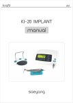
5. Mounting and electric connection
Series
5.1 Fix the Handpiece Holder 27 to the right side of the Control
Unit with bolt and washer.[Fig.7]
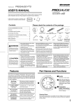
5.2 Plug the DC Motor Cord 25 into the DC Motor Connector 15
located in the front of the Control Unit.[Fig.8]
5.3 Plug the BLDC Motor Cord 23 into the BLDC Motor
Connector 16 located in the rear of the Control Unit and
then tighten the plug nut.[Fig.9]
5.4 Plug the Foot Pedal Cord 32 into the Foot Pedal Connector
17 located in the rear of the Control Unit.[Fig.9]
5.5 Plug the Power Cord 33 into the Power Connector 18 in the
rear of the Control Unit.[Fig.9]
|zlyNzGthu|hs
Read this User's Manual thoroughly for safety before operating the unit.
Wear safety glasses for eye protection.
[Fig.1]
ྙ
ྚ
27
25
15
[Fig.8]
REFERENCE
AUTO
CRUISE
ྛྜྷ
ྜྞ
ྟ
A:DC
B:BLDC
MOTOR
SPEED
X1000RPM
A
B
RUN
ྠ
MOTOR
ྛ
ྜ
ྜྷ
ྞ ྛྜྷ
ྜྞ
ྡ
BLDC
MOTOR
SPEED
X1000RPM
B
RUN
AUTO
CRUISE
ྡ
FWD / REV
FWD / REV
HAND / FOOT
ྡྷ
ྣ
Fo
rC
onn
ectin
g
ྦྷ
MOTOR
ce
pie
and
BLDC or DC Motor H
ྤ
ྡྷ
ྥ
ྣ
HAND / FOOT
ྦ ྦྷ
ྦ
A
FRONT SIDE
AUTO
CRUISE
A
RUN
ྟ
B
ྠ
MOTOR
ྡ
FWD / REV
ྤ ྡྷ
ྥ ྣ
Fo
e
rC
iec
onn
ndp
ectin
g BLDC Motor Ha
A: DC
B: DC
MOTOR
SPEED
X1000RPM
18
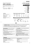
- You can put the several kinds of tool burs on the surface of
magnetic bur holder which is installed in side of controller.
(Protect from ferrous metal dust.)[Fig.10]
ྥ
Fo
rC
ces
onn
dpie
ectin
g 2 DC Motor Han
ྦ
A
FRONT SIDE
FRONT SIDE
23
17
CAUTION
33
32
- Make sure that all cords are connected safely and properly
and that the Power Switch is off before plugging in the Power
Cord.
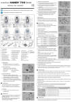
6. How to operate
HANDY 702
200-240V~ 50/60Hz 30W
MOTOR A: BLUSH MOTOR
MOTOR B: BLUSH MOTOR
MODEL:
INPUT:
HANDY 701
200-240V~ 50/60Hz
40W
MOTOR: BLUSHLESS MOTOR
MODEL:
HANDY 700
200-240V~ 50/60Hz
40W
MOTOR A: BLUSH MOTOR
MOTOR B: BLUSHLESS MOTOR
MODEL:
INPUT:
INPUT:
OUPUT:
OUPUT:
Max 90 min
SERIAL No.
Max 90 min
WARNING
REPLACE FUSE AS MARKED
T1.6 AL 250V
SERIAL No.
Max 90 min
SERIAL No.
MADE IN KOREA
WARNING
REPLACE FUSE AS MARKED
T1.6 AL 250V
WARNING
REPLACE FUSE AS MARKED
T1.6 AL 250V
DC 32V
OPERATING:
DC 32V
OPERATING:
DC 32V
OPERATING:
OUPUT:
15
MADE IN KOREA
MADE IN KOREA
MOTOR
18
www.saeyang.com
17
MOTOR
19
18
16
17
19
www.saeyang.com
16
[Fig.2]
21
B
19
18
www.saeyang.com
a. Set Power Switch to off.
b. Plug the Power Cord 33 into an electric outlet.
c. Set the Speed Control Knob ྡ to the slowest position.
d. Turn on the Power Switch ྦ .
e. Select motor A or B by momentarily pressing Motor
Selector Switch ྟ . (except for HANDY701)
17
B
REAR SIDE
23
22
REAR SIDE
28
29
30
25
HANDY700
REAR SIDE
32
31
33
HANDY702
24
20
26
27
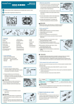
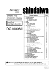
1. Components
ྙ Control Unit
ྚ Speed Display
ྛ Motor Run Switch
ྜ Motor Run LED
ྜྷ Auto Cruise Switch
ྞ Auto Cruise LED
ྟ Motor Selector Switch
ྠ Motor Selector LED
ྡ Speed Control Knob
ྡྷ Forward/Reverse Selector Switch
ྣ Forward/Reverse Selector LED
ྤ Hand/Foot Selector Switch
ྥ Hand/Foot Selector LED
ྦ Power Switch(Power Lamp)
ྦྷ DC Motor Connector
16 BLDC Motor Connector
17 Foot Pedal Connector
18 Power Connector
19 Fuse Holder
20 Test Bur
21
22
23
24
25
26
27
28
29
30
Collet Chuck
BLDC Motor Handpiece
BLDC Motor Cord
DC Motor Handpiece
DC Motor Cord
Handpiece Stand
Handpiece Holder
Chuck Wrench
Spanner
Chuck Joint Wrench
31
32
33
Foot Pedal
Foot Pedal Cord
Power Cord
REFERENCE
- BLDC MOTOR indicates Brushless DC micromotor.
- DC MOTOR indicates Carbon brush micromotor.
[Fig.3]
2. Complete set[Fig.3]
- Control Unit, Power Cord
- Handpiece Holder, Bolt, Washer
- Handpiece
- Handpiece Stand
- Foot Pedal
- Tools
[Fig.4]
hjXWW¥XYW}SG\WV]Wo¡
hjYWW¥Y[W}SG\WV]Wo¡
CAUTION
{ZUX\hsGY\W}
OhjXWW¥XYW}P
{XU]hsGY\W}
OhjYWW¥Y[W}P
MOTOR B
(BLDC Motor Handpiece)
Motor Selector LED ྠ
lights orange color
MOTOR A
(DC Motor Handpiece)
Motor Selector LED ྠ
lights green color
MOTOR B
(DC Motor Handpiece)
Motor Selector LED ྠ
lights orange color
[Fig.11]
HANDY700
HANDY702
ྠ
ྛྜྷ
ྜྞ
ྟ
ྡ
ྡྷ
ྣ
ྥ ྤ
ྦ
f. Select the rotation direction by pressing Forward/
[Fig.12]
Reverse Selector Switch ྡྷ .
HANDY701
6.1 For hand mode operation, follow steps a. through f.
g. Press the Hand/Foot Selector Switch ྤ to "HAND".
ྞ
ྛ
(Hand/Foot Selector LED ྥ lights green color)
ྜ
ྜྷ
h. Press the Motor Run Switch ྛ to run the motor.
(Motor Run LED ྜ lights green color)
ྡྷ
i. Set the Speed Control Knob ྡ to desired speed.
ྣ
j. The motor stops by pressing again the Motor Run
Switch ྛ .(Motor Run LED ྜ is turned off)
ྥ ྤ
ྦ
6.2 For foot mode operation, follow steps a. through f.
g. Press the Hand/Foot Selector Switch ྤ to "FOOT".(Hand/Foot Selector LED ྥ lights
orange color, Motor Run LED ྜ lights green color)
h. Set the Speed Control Knobྡ to desired maximum speed.
i. Press the Foot Pedal 31 to run the motor.
6.3 Auto Cruise Mode
- When the Foot Pedal is used, the Auto Cruise feature allows the speed to be maintained when
pressure is removed from the Foot Pedal. Activate by pressing the Auto Cruise Switchྜྷ and
keeping the Foot Pedal depressed for 2 seconds. Deactivate by pressing the Foot Pedal.
- Do not exceed the maximum operating speed of the Control Unit because its operation
at too high speed may result in damage to the handpiece, as well as personal injury.
- Before turning off the Power Switch, it is surely required to make sure that the motor has
been stopped.
- When the unit is not in use, for maximum safety, unplug the Power Cord.
- This function is for using the motor handpiece in safety to set display of maximum rotation speed.
a. Turn on the Power Switch ྦ while pressing the Motor Run Switch ྛ and wait for a beep.
Release the Motor Run Switch.
b. Select the desired motor mode "dc" or "bc" by pressing the Motor Select Switch ྟ .
c. Set the maximum speed of the motor handpiece which you want to use by repeatedly
pressing the Hand/Foot Selector switch ྤ .
Switch
Model
19
4. Installation
MOTOR A
[Fig.5]
4.1 The Control Unit ྙ should be installed on the working table.
[Fig.6]
[Fig.6]
- The Control Unit should rest on a flat, steady surface. Avoid
blocking the ventilation openings in the bottom of the case.
- Use the Control Unit in locations that have a temperature
range between 040. Avoid excessively dusty, hot, or
humid locations.
Motor Selector LED ྠ
lights green color
[Fig.10]
7. Rotation speed display set mode
- Never plug or unplug the Power Cord with wet hands to avoid
electric shock.
- Use only an earthed(grounded) AC power receptacle.
CAUTION
MOTOR A
(DC Motor Handpiece)
Magnetic
Bur Holder
CAUTION
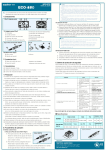
3. AC power input
3.1 Check the electric rating label (AC100~120V, 50/60Hz or
AC200~240V, 50/ 60Hz ) affixed to the rear of the Control
Unit[Fig.4]
3.2 Replace fuse with identical type and rating only.(T3.15AL
250V in case of AC100~120V, T1.6AL 250V in case of AC
200~240V) The Fuse Holder 19 contains a spare fuse.[Fig.5]
[Fig.9]
16
HAND / FOOT
ྤ
MOTOR
[Fig.7]
Motor Selector Switch ྟ
Hand/Foot Selector Switch ྤ
"dc" displayed(DC Motor Handpiece)G
25,30,35,40,45,50( x1,000rpm )
HANDY700
MOTOR B "bc" displayed(BLDC Motor Handpiece)
HANDY701
MOTOR A
HANDY702
MOTOR B
I
"bc" displayed(BLDC Motor Handpiece)
I
"d1" displayed(DC Motor Handpiece)
G
"d2" displayed(DC Motor Handpiece)
I
I
CAUTION
- Please use this set mode only when you change to operate with other kind of micromotor
handpiece which has different specification of motor.
8. Maximum Torque Set Mode
- This setting is used to match the maximum output of the control unit to the maximum torque
capability of the handpiece, or to prevent damage to the bur.
a. Turn on the Power Switch ྦ while simultaneously pressing Forward/Reverse Selector Switchྡྷ
when you hear a beep, release the Forward/Reverse Selector Switch.
b. Refer to the table below. Select the motor for setting maximum torque, c1/Motor A, c2/Motor B,
by pressing the Motor Select switch ྟ .
c. Set the electric current (ampere) value for maximum torque of the motor handpiece by pressing
Hand/Foot Selector switch ྤ repeatedly until the desired amperage value is displayed.
The higher the current value, the more powerful the torque.
Switch Motor Selector Switch ྟ Hand/Foot Selector Switch ྤ
Model
MOTOR A
G 3a, 4a, 5a
1a, 2a,
"c1" displayed
recommended
"c2" displayed
1a, 2a, 3a, 4a, 5a, 6a, 7a
less than 6a
"c1" displayed
1a, 2a, 3a, 4a, 5a, 6a, 7a
less than 6a
MOTOR A
"c1" displayed
1a, 2a, 3a, 4a, 5a
less than 3a
MOTOR B
"c2" displayed
1a, 2a, 3a, 4a, 5a
less than 3a
HANDY701
11. Technical data
11.1 Error code
Error code
Status
"1E"
Motor sensor error
"2E"
Motor lock error
"4E"
Overvoltage
detection error
1. The circuit of the Control Unit is defective.
"5E"
Overheat error
1. The Control Unit has been excessively operated under a high load
condition for too long time.
2. The Control Unit has been exposed to an excessive hot environment.
3. Air openings are blocked.
4. Temperature sensor is troubled.
"6E"
Overdrive error
1. The operated under a high load condition or it
was suddenly stopped after being started in good condition.
less than 3a
HANDY700
MOTOR B
- Be sure to insert the Bur shank all the way, until it touches the back of the Collet Chuck. Then
tighten the Collet Chuck. If the Bur is used while not inserted completely, it is very dangerous
because vibration may cause it to come out.
Cause
HANDY702
CAUTION
Do Not select a current value which exceeds the rating of the motor handpiece, which may cause
shortening motor life or damage the control unit.(Consult a qualified technician if possible.)
REFERENCE
9. Handling of the Motor Handpiece(SDE-BH60)
G
Corrective actions
The Power Lamp
does not light.
Check that the fuse is blown.
Make sure that the Power Switch is
working properly.
Chuck Handle
9.1 Insertion or Removal of Bur
The Bur 20 can be replaced by turning the Chuck Handle
clockwise. After replacing the Bur, the Chuck Handle must
be turned counterclockwise to be securely held. [Fig.13]
9.2 How to mount and dismount the Collet Chuck
Turn the Collet Chuck 21 counterclockwise while opened
[Fig.14]
to dismount. If the Collet Chuck can not be turned manually,
use the Chuck Wrench 28 to dismount it. To mount the
21
Collet Chuck, it is required to first open the Chuck Handle
and then insert the Collet Chuck and the Bur. [Fig.14]
9.3 How to disassemble the Chuck Handle and the Motor
The Chuck Handle and the Motor are disassemble by
28
continuously turning the Chuck Handle counter clockwise.
[Fig.15]
9.4 How to disassemble the Motor and the Motor Cord
The Motor Cord 23 is disassembled by continuously turning [Fig.15]
the Motor counterclockwise.[Fig.15]
Check points
Make sure that the Power Cord is
correctly plugged into the outlet and
the control unit.
21
20
1. The Collet Chuck is opened.
2. The Motor Handpiece is mechanically defective.
3. The Motor Handpiece is electrically defective.
11.2 Troubleshooting
Troubles
To check the values of maximum rotation speed and maximum torque which are already set, turn
on the Power Switch ྦ while simultaneously pressing Motor
Select Switch ྟ (Auto Cruise Switchྜྷ in Handy 701), the set [Fig.13]
Motor
values are on the Speed Display LED ྚ one by one.
1. One or more hall sensors defective
2. The Motor Cord is unplugged or defective.
3. The Motor Cord is broken.
Check if the Collet Chuck is
"2E"
displayed opened.
If opened, close the Collet Chuck. If the same
error is still displayed, then repair it.
"4E"
The circuit of the Control Unit it is
displayed defective.
Repair it.
The
"5E"
motor displayed Check if work place temperature is too
high.
does
not
Check if control air opening is blocked.
run.
Temperature sensor is troubled.
"6E"
Check if the Collet Chuck is opened.
displayed
Check if the shaft of the Motor
Handpiece can rotate freely.
t
CAUTION
Make sure that the Foot Pedal Cord
23
- Use only recommended burs.
The Foot Pedal is properly plugged in.
yG
does not work.
- Always remove dirt before replacing a bur.
The Hand/Foot Selector Switch is
set to "HAND".
- After replacing a bur, make sure that the Collet Chuck is
The
Motor
securely held before running the Motor.
Handpiece
The ball bearings are defective.
- DO NOT try to adjust the Chuck Handle while the motor is running to prevent the unit from being
overheats while
in operation.
damaged.
Make sure that the Collet Chuck is
- When the Motor Handpiece is not in use, it is recommended that a bur is kept inserted in the Chuck.
The Motor
free from dirt.
- Always put the Motor Handpiece on the Handpiece Stand 26 or Handpiece Holder 27 while not is
Handpiece
The rotation speed is too high.
vibrates
use.[Fig.9] Special care must be taken not to drop it on the floor.
excessively
- Thoroughly clean the Collet Chuck and Burs before reassembling. Clean at least once a week for
and is unusually Check if the bur shaft.
noisy.
longer life.
Make sure that ball bearings are in
good condition.
- Special care must be taken that the Chuck Handle and the Motor are free from and dirt during
disassembly.
12. Specification
- The spindle and the motor should be disassembled only by a qualifed repair facility.
- Control Unit
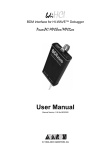
10. Allowable rotation speed
Model Name
10.1 This chart is a general guide for the maximum rotation speed of conventional burs. The
allowable rotation speed can be slightly different, depending on bur materials or types.
ڈٻڋڋڋڇڋڐ
ڈٻڋڋڋڇڐڏ
Input
Restart the Control Unit after keeping it stopped
for about 10 minutes. If the same error is still
displayed, repair it.
If too warm, move the Control Unit to a location
an indoor temperature of 0ං40.
Unblock air opening.
Repair it.
Press the Auto Cruise Switch or turn off, then on,
then press the Motor Run Switch.
If the same error is still displayed, then repair it.
If opened, tighten it by turning the Chuck Handle.
If it cannot be rotated with the chuck closed, the
spindle of the Motor Handpiece is defective.
Repair it.
Plug in the Foot Pedal Cord correctly.
Set the Hand/Foot Selector Switch to ˈFOOTˉ.
Repair the Motor Handpiece.
Thoroughly clean the Collet Chuck.
Reduce the rotation speed. Refer to "Allowable
rotation speed" chart.
Replace with new one.
Repair the Motor Handpiece.
Weight
Size
Handpiece type
Brushless Motor
or Brush Motor
HANDY700
AC 100~120V 50/60 Hz
AC 200~240V 50/60 Hz
2.7kg
G
137(W)x232(D)x180(H)
HANDY701
"
2.7kg
137(W)x232(D)x180(H)
only Brushless Motor
HANDY702
"
1.9kg
137(W)x232(D)x180(H)
Brush Motor
(two connectors)
URWDWLRQ#VSHHG^USP`
ڈٻڋڋڋڇڋڏ
Repair if the Power Switch is defective.
Correctly plug in the Motor Cord. If the same
error is continuously displayed,replace the Motor
Cord.
Check if the Control Unit has been
excessively used under a high load
condition.
jGo
Replace with a recommended fuse. If the fuse
is blown again, repair the unit.
Check that the Motor Cord is
"1E"
displayed plugged in properly.
Check if the Control Unit has been
used at a high load for a long time.
jGo
Correctly plug in the Power Cord.
ڈٻڋڋڋڇڐڎ
Model Name Weight
ڈٻڋڋڋڇڐڍ
ڈٻڋڋڋڇڋڍ
SDE-FS60N
ڈٻڋڋڋڇڐڌ
ڈٻڋڋڋڇڋڌ
384g
Size
110(W)x172(D)x42(H)
Model Name Weight
SDE-HS10
G
68g
Size
60(W)x110(D)x45(H)
If you have any questions, please do not hesitate to contact us.
ڈٻڋڋڋڇڐ
ڈٻڋ
- Handpiece Stand
- Foot Pedal
ڈٻڋڋڋڇڋڎ
more than φڋڏ
φڋڏۙړڍ
φړڍۙړڌ
φړڌۙړ
φړۙڏ
φڏۙڍ
less than φڍ
CAUTION
- Make sure not to exceed the maximum rotation speed specified by the manufacturer or distributor
for the bur being used.
- Large burs, even when operated below maximum rated speed, may begin to vibrate. Speed should
be reduced immediately to prevent damage to the bur, handpiece, or operator.
- Always use standard burs.
110B 3L SEONG SEO-IND COMP, 306-107
JANG-DONG, DAL SEO-GU, DAEGU, KOREA.
TEL : 82-53-582-9000~2, FAX: 82-53-581-9003
SEOUL OFFICE(A/S CENTER) TEL : 82-2-775-9023~5, FAX : 82-2-775-9026
http://www.saeyang.com