1
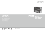
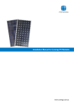
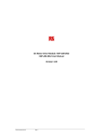
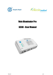
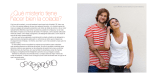
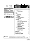
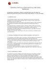
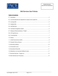
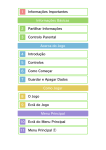
CNBM International Corporation
Solar Module Installation and User Manual
Thank you for selecting solar panel from CNBM.
In order to use the solar panels properly, please read this Installation Manual
carefully and completely before any operating.
Catalogue:
About Solar Panel
Page 2
Performance and Characteristics
Page 3
Safety Warning
Page 4-9
Installation
Page 10-16
Maintenance & Inspection
Page 17
The modules are qualified for application class A: Hazardous voltage (IEC 61730: higher
than 50V DC; EN 61730: higher than 120V), hazardous power applications (higher than
240W) where general contact access is anticipated (modules qualified for safety through EN
IEC 61730-1 and -2 within this application class are considered to meet the requirements for
Safety Class II)
Page 1 of 20
About Solar Panel
What is solar panel?
Solar panel is a big semiconductor (PN diode) which can transfer sun energy to
electrical energy without any help from mechanical energy and it is a quiet and
clean energy generator which can create DC electricity continuously under the
sunlight.
Theory
Under the sunlight, the cells in the modules will produce electrons and cavities
by photo-emission which is influenced by internal electrical field, the electrons
will go towards and assemble at N-silicon and cavities will go towards and
assemble at P-silicon. As a result, the electromotive force will occur, if they are
connected with exterior load, the DC electricity will be created.
Page 2 of 20
Performance
The module is high efficient due to adopting high-efficent cell
The module is high reliable due to adopting high transparent tempered glass
The structure of module is wind-resistant.
Characteristics
(From CNBM-240P to CNBM-))
Voltage at
point of max
power
Vmpp(V)
35.0±0.5V
35.0±0.5V
35.3±0.5V
35.3±0.5V
Current at
point of
max
power
Impp(A)
6.86±0.5A
7.0±0.5A
7.08±0.5A
7.22±0.5A
Open
Circuit
Voltage
Voc(V)
42.0±0.5V
42.0±0.5V
42.4±0.5V
42.4±0.5V
Short
Circuit
Current
Isc(A)
7.68±0.5A
7.84±0.5A
7.93±0.5A
8.09±0.5A
Max System
Voltage
(V)
Max
Power
Pm(W)
and
Type
Class A
1000
240
CNBM240P
1000
245
CNBM245P
Over-curren
t
Protection
24
Maximu
m
parallel
configura
tions
1
Class A
24
1
15A
Class A
24
1
15A
1000
250
CNBM250P
Class A
24
1
15A
1000
255
CNBM255P
Class A
24
1
15A
Class A
24
1
15A
35.5±0.5V
7.32±0.5A
42.6±0.5V
8.20±0.5A
1000
260
CNBM260P
35.5±0.5V
7.46±0.5A
42.6±0.5V
8.36±0.5A
1000
265
Page 3 of 20
Application
class
Maximum
series
configuratio
ns
15A
CNBM265P
35.8±0.5V
35.8±0.5V
36.0±0.5V
36.0±0.5V
36.0±0.5V
28.5±0.5V
7.54±0.5A
7.68±0.5A
7.78±0.5A
7.92±0.5A
8.06±0.5A
7.02±0.5A
43.0±0.5V
43.0±0.5V
43.2±0.5V
43.2±0.5V
43.2±0.5V
34.2±0.5V
8.45±0.5A
8.60±0.5A
8.72±0.5A
8.87±0.5A
8.97±0.5A
7.86±0.5A
Class A
24
1
15A
1000
270
CNBM270P
Class A
24
1
15A
1000
275
CNBM275P
Class A
24
1
15A
1000
280
CNBM280P
Class A
24
1
15A
1000
285
CNBM285P
Class A
24
1
15A
1000
290
CNBM290P
Class A
30
1
15A
1000
200
CNBM200P
Class A
30
1
15A
28.5±0.5V
7.19±0.5A
34.2±0.5V
8.05±0.5A
1000
205
CNBM205P
29
1
15A
7.24±0.5A
34.8±0.5V
8.11±0.5A
1000
210
CNBM210P
Class A
29.0±0.5V
Class A
29
1
15A
1000
215
CNBM215P
Class A
28
1
15A
1000
220
CNBM220P
225
CNBM225P
Class A
28
1
15A
Max
Power
Pm(W)
And
Type
230
CNBM230P
Application
Class
Maximum
series
configuratio
ns
Maximu
m
parallel
configura
tions
Over-curren
t
Protection
28
1
15A
29.0±0.5V
29.5±0.5V
7.41±0.5A
7.46±0.5A
34.8±0.5V
35.4±0.5V
8.30±0.5A
8.36±0.5A
29.5±0.5V
7.63±0.5A
35.4±0.5V
8.55±0.5A
1000
Voltage at
point of max
power
Vmpp(V)
Current at
point of
max
power
Impp(A)
Open
Circuit
Voltage
Voc(V)
Short
Circuit
Current
Isc(A)
Max System
Voltage
(V)
30.0±0.5V
7.67±0.5A
36.0±0.5V
8.59±0.5A
1000
Page 4 of 20
Class A
30.0±0.5V
7.83±0.5A
36.0±0.5V
8.77±0.5A
1000
30.0±0.5V
8.00±0.5A
36.0±0.5V
8.96±0.5A
1000
235
CNBM235P
240
CNBM240P
Class A
28
1
10A
Class A
28
1
10A
With 72x5 mono c-Si cells:
Voltage at
point of max
power
Vmpp(V)
Current at
point of
max
power
Impp(A)
Open
Circuit
Voltage
Voc(V)
Short
Circuit
Current
Isc(A)
Max System
Voltage
(V)
35.0±0.5V
4.43±0.5A
42.0±0.5V
4.96±0.5A
1000
35.0±0.5V
4.57±0.5A
42.0±0.5V
5.12±0.5A
1000
35.0±0.5V
4.71±0.5A
42.0±0.5V
5.28±0.5A
1000
35.5±0.5V
4.79±0.5A
42.6±0.5V
5.36±0.5A
1000
35.5±0.5V
4.93±0.5A
42.6±0.5V
5.52±0.5A
1000
36.0±0.5V
5.0±0.5A
43.2±0.5V
5.6±0.5A
1000
36.0±0.5V
5.14±0.5A
43.2±0.5V
5.76±0.5A
1000
Max
Power
Pm(W)
And
Type
155
CNBM
-155D
160
CNBM
-160D
165
CNBM
-165D
170
CNBM
-170D
175
CNBM
-175D
180
CNBM
-180D
185
CNBM
-185D
Applicatio
n
Class
Maximum
series
configuratio
ns
Maximu
m
parallel
configura
tions
Over-curren
t
Protection
Class A
24
1
15A
Class A
24
1
15A
Class A
24
1
15A
Class A
24
1
15A
Class A
24
1
15A
Class A
24
1
15A
Class A
24
1
15A
Note: Rated electrical characteristics are within ±10 percent of the indicated values of Isc, Voc, Pm under
Standard Test Conditions. (Irradiance of 1000W/m², Am 1.5 spectrum and a cell temperature of 25°C
(77°F)
Page 5 of 20
Safety Warning
In order to use the modules properly, avoiding property losses or injuring the
operater or anyone else, warnings and some other caution signs are printed on
the solar modules and Manuals.
Sign Introduction
Sign
Introduction
Means ” Misoperation will cause a risk of lethal or personal serious injury ”
Warning
Means”Misoperation will cause a risk of injuring or porperty loss ”
Caution
Graph introduction
Graph
Introduction
Prohibited (proceeding not permitted )
The details will be described in the signs, graphs and texts
Compulsion (proceeding is compulsory )
The details will be described in the signs ,graphs and texts
Caution (Warning included)
The details will be described in the signs or graphs and texts
Page 6 of 20
General Warnings
warning
Solar module installation,maintenance,removal and resetting shall only be done by
professionals
Before you attempt to install wire, operate and maintain the PV module,
please make sure that you completely understand the information described in this
installation manual.
If there were defects, there is a risk of electrical shock or fire.
When installing,wiring,operating, removing and maintaining modules, pay attention to the risk of
electrical shock
If module is shined by sunlight or other illuminator, the DC electricity will be produced.
Artificially concentrated sunlight shall not be directed on the module.
Under normal conditions, a photovoltaic module is likely to experience conditions that
produce more current and/or voltage than reported at standard test
conditions.Accordingly, the values of ISC and VOC marked on this module should be
multiplied by a factor of 1.25 when determining component voltage ratings, conductor
ampacities, fuse sizes,and size of controls connected to the PV output.please refer to
Section 690-8 of the National Electrical Code for an additional multiplying factor of 125
percent(80 percent derating) which may be applicable.
If modules are connected in series or parallel, the voltage and current will increase,
the danger will be increased tremendously accordingly.
When installing, wiring or maintaining modules, in order to prevent producing the DC
electricity, please cover the module surface with sufficiently opaque stuff.
When installing, wiring or maintaining modules, please use protective instruments
such as rubber gloves.
Do not connect the PV modules directly to the loads such as
motor since the variation of the output power depending on the solar irradiation
cause damage for the connected motor.
1:In the case of a blushless motor, the lock function becomes active and the hall IC is
most likely to be damaged.
2:In the case of a brush type motor, the coil is most likely to be damaged.
If high reliability is required (the machine is related to personal life), please don’t use those modules
Output is unstable
Serious accidence such as lethal injure may occur.
Page 7 of 20
Warning for Installation
1. Always wear protective head gear, insulating gloves and safety shoes (with rubber soles).
2. Keep the PV module packed in the carton until installation.
3. Completely cover the PV module surface with an opaque material during PV module installation and
wiring.
4. Plug in the connector tight and ensure the wiring work.
5. Wear a safety belt if working far above the ground.
. Bind cables by the insulation locks. Drooping down of cables from the terminal box could possibly cause
various problems such as animal biting electricity leakage in puddle.
Warning
Installing, maintaining, removing and
resetting modules shall only be done
by professionals.
Don’t stand or stamp on the solar
modules There is a risk of injury or
electric shock if glass is
broken and it is slippery
which may make injury to
someone.
Do not touch the terminal box and the
end of output cable ends (connectors)
with bare hands during installation or
under sunligh, regardless of whether
the PV module is connected to or
disconnected from the system.
Also do not perform any
work if the terminals of PV
module are wet.
Sharp stuff prohibited. It
puncture the back of module
There are risks of
electrical shock, electricity
leakage and solar module’s
service life may be shortened
may
Don’t wear steel stuff
like rings. There is a risk of
electrical shock
Don’t put wires between frame and prop.
The wire may be damaged and cause
electrical shock and fire
When connecting modules with
other controlling device please entrust
professionals
Don’t damage or process
wiring material. It may cause
a risk of electrical shock.
Warning
Page 8 of 20
Grounding
Don’t install solar modules on movable
objects such as doors,vehicles.
If not connected properly, it will cause a
risk of electrical shock. Please don’t
connect the cable with any other pipes
such
as
gas
pipe,
thunder-avoiding
rod
water
etc.
Each
pipe,
PV
The glass may be damaged and cause injury due
to libration.
module has a hole on each side with a
grounding sign
.
An example of ground connection using a
bolt, nut, and washer retaining a ground lug
is shown in the following figure. The
screwing rate for nut is about 1.2 N.M
Do not touch the PV module unnecessarily
during installation. The glass surface and
the frames get hot. There is a risk of burn,
or you may collapse because of electric
shock.
Alternately, the grounding and bonding
equipment,
type
1954381-1,
by
Tyco
Electronics Corp can be used to provide the
Do not work under rain, snow or windy
conditions.
grounding connection to the module frame,
as illustrated in the following diagram.
Remarks:
Screw size: M5 screw Earth cable diameter: please use a 4mm earth cable.
Page 9 of 20
Warning for Operating
Warning
Do not open cover of junction box, it
may result in electric shock.
Do not damage or
process wiring material,
which may cause risk of electric
shock.
Don’t let children approach modules
There is risk of electric shock or injury.
Do not prick back of solar
module with sharp objects
otherwise may result in electric
shock, electricity leakage or make
solar module damaged
Don’t stand on or step on the solar modules because the solar module
may be damaged and people may be injured if slip down.
Page 10 of 20
Caution
don’t touch solar modules
The module will become high temperature under sunshine, and may cause a risk of scalding
Page 11 of 20
Warning for Maintenance
Warning
Don’t open cover of junction
box and clean inside with liquid, it may result in
electrical shock.
Do not use damaged,
abnormal solar module
which may cause risk of an electric
shock. If so please contact CNBM.
Don’t immerse the solar modules in
liquid, it may result in electrical shock
Don’t deform , mend solar
module, it may result in
electric shock or be wounded.
Don’t stand or step on solar module. The module may be damaged due to its
glass surface and it may make person injured when they slip down.
Don’t touch the cable of the solar module, since DC electricity will be
produced when solar module is under sunlight, please pay attention to this
to avoid electrical shock.
Page 12 of 20
Installation
Warning
Installing, repairing, removing and resetting solar modules shall only be done by
professionals
Caution
z
z
z
Don’t put heavy objects on solar module
Don’t let optical lens and other spotlight objects to shine
the modules directly.
Don’t toss or drop the solar modules
Installation shall be in accordance with CSA C22.1, Safety Standard for
Electrical Installations, Canadian Electrical Code, Part 1.
Attention for installation
The modules shall be mounted so that the junction box shall be in the
uppermost position to minimize the ingress of water
In case of series connection, the maximum open circuit voltage must not be
greater than the specified maximum system voltage. The voltage is proportional
to the number of series. In case of parallel connection, please be sure to take
proper measure (e.g. fuse for protection of module and cable from over current,
and/or blocking diode for prevention of unbalanced strings voltage) to block the
reverse current flow. The current may easily flow in a reverse direction.
Page 13 of 20
Site Selection
Please make sure that there is no obstruction in the surroundings of the site of
installation. And select the site without shadows from trees or buildings,
enabling the module to be shined by sun frequently. Especially in very hot
weather, please pay attention the modules can’t be shadowed partly.
Furthermore, in different season, the dimension of shadow caused by plant or
any other objects will be changed and may shadow some portions of solar
modules, resulting in power generation reducing. Take proper steps in order to
maintain reliability and safety, in case the PV modules are used in areas such as:
heavy snow areas/extremely code areas/strong wind areas/installation over, or
near, water/areas where installations are prone to salt water damage/small
islands or desert areas.
Installation direction: In the Northern Hemisphere, the PV modules should
typically face south, and in the Southern Hemisphere, the PV modules should
typically face north.
Tilt angle:
The title angle of the PV module is the measured between the PV module and a
horizontal ground surface. The PV module generates the maximum output
Page 14 of 20
power when it faces the sun directly.
For the standalone systems with a battery where the PV modules are attached
to a permanent structure, the tile angle of the PV modules should be determined
to optimize the performance when the sunlight is the scarcest. In general, if the
electric power generation is adequate when the sunlight is the scarcest, then
the angle chosen should be adequate during the rest of the year. For
grid-connected installations where the PV module at the angle equal to the
latitude of the installation site so that the power generation from the PV module
will be optimum throughout the year.
Sunlight
tilt angle
PV module will get maximum output of power generation when sunlight irradiates on
their surfaces vertically. But if operating time and operating purpose are limited, the
above-mentioned design may not be optimum.
Page 15 of 20
Support Structure
In order to make PV modules have a long service life outside please pay
attention to the following items:
z Adopting strong and safe structure.
z Choosing appropriate materiel for solar modules
z Adopting appropriate method for anticorrosion
z Following all kinds of regulations concerned
z Don’t damage any parts of modules for power generation.
z The site shall be in compliance with ambient and climate.
z Be easy to maintenance
z The foundation shall be done by professional designer or construction
company
z The assembly is to be mounted over a fire resistant roof covering rated
for the application.
Page 16 of 20
Installation
PV module installation
Caution
Use the long side of module frame as top, bottom side with installation holes to install
modules.
If PV modules were blow away, it will be very dangerous.
Applying M6 or M8 stainless steel screws with power about 5~8N.M
In salty area please take appropriate methods to prevent solar modules from corrosion
Wiring and connection
900mmX4mm² cable for CNBM-160D---CNBM-180D solar modules, Temperature for interior
and exterior of the cable can’t exceed 85℃ and 55℃ separately. Diodes were installed in the
solar modules.
If solar modules from CNBM were connected with other solar modules, the output of
power generation will be deteriorated and may cause bad effect to solar modules. So
please avoid this.
When PV modules are generating DC electricity please use the diodes or other
applicable methods to prevent reversed current. Diodes are not subsidiary components
of the solar modules
Note: Parallel configuration is not limited in case of taking proper measure (e.g. fuse for
protection of module and cable from over current, and/or blocking diode for prevention of
unbalanced strings voltage) to block the reverse current flow.
Please make sure that all the information described in the installation manual is
Page 17 of 20
still valid and proper for your installation. The mounting method has been
verified by CNBM and NOT CERTIFIED by a third party organization.
The approved way to mount CNBM PV modules to a support structure is using
the bolt holes provided as described in the specifications. Although CNBM does
not specify or warrant frame clips or clamps, using frame clips (not provided) or
clamps module (not provided) is also possible when they are designed for PV
modules and with minimum dimensions on the sides of the module in
accordance with the instructions and drawings provided. If using frame clips or
clamps, the modules should be fixed rigidly and there shall be no damage to the
modules by deforming mounting structure against design load. CNBM does not
specify or warrant frame clips. The CNBM module warranty may be void if
customer-selected frame clips which are improper or inadequate with respect to
the module properties (including strength or material) or installation. Note that if
metal clips are used, there must be a path to ground from the clips. (for instance,
using star washers in the clip hardware set.) Please review the descriptions and
drawings carefully; not mounting the modules according to one of these
methods may void your warranty. These mounting methods are designed to
allow module loading of 2400pa.
Page 18 of 20
Page 19 of 20
Wiring
Wiring
Please observe the correct cable connection polarity when installing the
modules. If not connected properly, the bypass diode could be destroyed.
PV modules can be wired in series to increase voltage as shown in figure
1.
PV modules can be wired in parallel to increase the current as shown in
figure 2.
Page 20 of 20
Removal
Only professionals can disassemble or reinstall the solar modules.
Page 21 of 20
Maintenance & Inspection
Routine Inspection
It is unnecessary to do inspection everyday; our suggestion is one time for one
year.
If the dirt were built-up please clean the surface with soft sponge with water.
Inspection for Wind and Rain Hazard or Earthquake
When wind and rain hazard or earthquake happens, please check whether
something dropped on the PV modules and made some damages to them.
Inspection for Salt or Snow Hazard
Please make a schedule to inspect whether PV modules were corroded
After heavy snow, please check the condition of solar modules.
CNBM reserve the right to revise the models/contents without notice.
CNBM(USA) CORP
17800 castleton st., suite 558 City of Industry,CA , 91748 USA
Phone
0016268106368
E-Mail
[email protected] Website:
Fax
0016268106853
www.cnbmsolar.com
Page 22 of 20