1
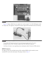
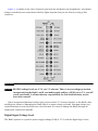
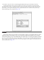
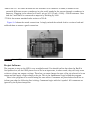
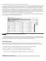
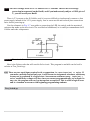
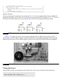
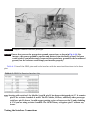
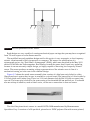
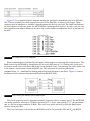
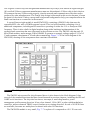
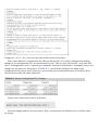
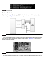
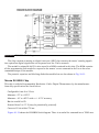
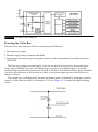
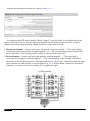
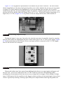
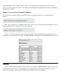
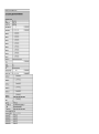
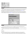
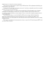
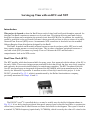
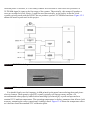
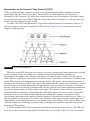
Figure 6–7
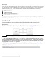
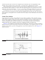
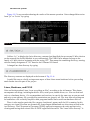
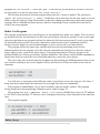
MCP3008 functional block diagram.
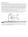
The analog signal is first selected from one of eight channels that may be connected to the input
channel multiplexer. Using one channel at a time is called operating in a single-ended mode. The
MCP3008 channels can be paired to operate in a differential mode, if desired. A single configuration
bit named SGL/DIFF selects single-ended or differential operating modes. Single-ended is the mode
used in this project.
The selected multiplexer channel is then routed to a sample-and-hold circuit that is one of the two
inputs to a comparator. The other input is from a digital-to-analog converter (DAC) that receives its
input from a 10-bit SAR. Basically, the SAR starts at 0 and rapidly increments to a maximum of 1023,
which is the largest number that can be represented with 10 bits. Each increment increases the voltage
appearing at the DAC’s comparator input. The comparator will trigger when the DAC’s voltage
precisely equals the sampled voltage, and this will stop the SAR from incrementing. The digital
number that exists on the SAR at the moment the comparator “trips” is the ADC value. This number is
then outputted, one bit at a time through the SPI circuit discussed below. All this takes place between
sample intervals. The actual voltage represented by the ADC value is a function of the reference
voltage VREF connected to the MCP3008. In our case, VREF is 3.3 V; therefore, each bit represents
3.3/1024 or approximately 3.223 millivolts. For example, an ADC value of 500 would represent an
actual voltage of 1.612 V, which was computed by multiplying .003223 by 500.
Serial Peripheral Interface
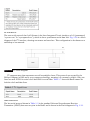
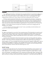
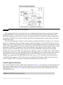
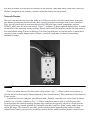
The Serial Peripheral Interface (SPI) was introduced in Chap. 1 as a synchronous serial (SS) data link
that uses one master device and one or more slave devices. There are a minimum of four data lines
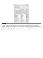
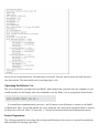
used with the SPI, and Table 6–2 shows the names associated with the master (RasPi) and the slave
(MCP3008) devices.
Table 6–2 SPI Data Line Descriptions