1
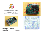
Scratch Raspberry Pi control
Pi Scratch V 2.76 B+
EDU Learning Board V-2 User Manual
Pridopia Limited
Tony Chang
30,Jun,2015
Raspberry Pi is a trademark of the Raspberry Pi Foundation
Contents
1. Install EDU Learning Board ------------------------------------------------------------ 2
2. Download & Install Pi_Scratch software --------------------------------------------- 3
Setting Scratch for Auto loading Pi_Scratch ----------------------------------------- 4
3. Enable i2c & Install i2c ----------------------------------------------------------------- 5
4. Other software pack install ------------------------------------------------------------- 7
5. Basic GPIO Function -------------------------------------------------------------------- 13
1. BASIC GPIO input & output demo ------------------------------------------------- 15
2. BASIC GPIO step motor demo ----------------------------------------------------- 17
6. EDU Learning Board support (E01) ---------------------------------------------------- 18
1. RTC setting --------------------------------------------------------------------------- 20
2. DHT 22 Temp/Humidity Sensor --------------------------------------------------- 24
3. Ultra Sonic Distance sensor -------------------------------------------------------- 26
4. 16X2/20X4 LCD --------------------------------------------------------------------- 27
5. 84X48 LCD ---------------------------------------------------------------------------- 29
6. Stepper Motor ------------------------------------------------------------------------ 33
7. 1-Wire DS18B20 Temperature Sensor -------------------------------------------- 35
8. DC 5V Mini Fan ---------------------------------------------------------------------- 37
9. IR PIR Motion Sensor Module ----------------------------------------------------- 39
10. IR remote control ------------------------------------------------------------------ 41
11. Servo Motor ------------------------------------------------------------------------- 45
12. HAT EEPROM READ/WRITE ------------------------------------------------------ 46
13. RFID reader ------------------------------------------------------------------------- 47
14. NRF24L01 Radio Frequency Reader module ----------------------------------- 52
15. Bluetooth console port ------------------------------------------------------------ 57
16. Bluetooth 2.0/4.0 AT command mode ----------------------------------------- 62
17. ESP8266 WiFi module ------------------------------------------------------------- 64
7. EDU Learning Board (E02) --------------------------------------------------------------- 71
Rx/Tx /RS232 / modules
-------------------------------------------------------- 72
Serial port console support --------------------------------------------------------- 72
8. EDU Learning Board (E03) ---------------------------------------------------------------- 74
RGB-W LED support ---------------------------------------------------------------- 75
Knight Rider LED kit support ------------------------------------------------------ 77
PWM Servo support ---------------------------------------------------------------- 79
9. Raspberry Pi B+ GPIO support ---------------------------------------------------------- 80
10. Python Test Code ------------------------------------------------------------------------ 81
Q&A
Pi_Scratch Install Q & A ------------------------------------------------------------- 83
How to Auto run Scratch & auto load Pi_Scratch example file ----------------- 87
How to make Image from three ZIP file ------------------------------------------ 89
First thing need do for Pi_Scratch ready Image ---------------------------------- 90
How to upgrade from old Pi_Scratch to new Ver Pi-Scratch ------------------- 91
VNC (VIRTUAL NETWORK COMPUTING) setting ------------------------------- 92
Setting Scratch to active Mesh function ----------------------------------------- 95
EDU Learning Board v2 GPIO List
1.The EDU Learning Board provide RTC clock with CR1220 3V Backup
Battery.
2. provide 2 switch control 2 sets Traffic light , provide python traffic light
program.
3. provide RFID Reader socket ( SPI signal) / NRF24L01 socket (SPI signal)
you can choose use RFID or NRF24L01 ( both use SPI signal)
4. Provide 2 extra i2c device input port, one for 3.3V, one for 5V
5. provide 3.3V power Regulator for 3.3V device ( RFID/ NRF24L01/ESP8266)
i2c device
6. provide DS18B20 temperature sensor socket (GPIO4)
7. provide IR Receiver sensor socket (GPIO23)
8. provide IR PIR motion sensor socket (GPIO23)
9 provide 1 5V 28BYJ-48 Step Motor socket (5V can select from Pi or
external)
(GPIO 17,18,27,22) Step Motor
10 provide 1 buzzer (GPIO24)
11 provide 2 sets traffic light
first set traffic light Red (GPIO19), Yellow(GPIO13), Green
(GPIO12) ,Switch 1(GPIO20)
second set traffic light Red (GPIO16), Yellow(GPIO21), Green
(GPIO26) ,Switch 2(GPIO6)
Install EDU Learning Board
(1) Install RTC Battery
Below are the new functions we added in V2
•
2 x R,Y,G LED display stand set
•
2 x Servo motor socket GPIO 18,24
•
HAT EEPROM 24c32 support on board
•
1 x DHT22 Temperature & Humidity sensor socket
•
HY-SRF05 Ultrasonic distance sensor socket
•
16x2/20x4 character LCD socket
•
84x48 Pixels Monochrome LCD socket
(2) Install PCB spacer
1
2
Download program pack from our web site
setting Auto login -> startx -> Scratch -> load file for Pi_Scratch
sudo wget http://pridopia.co.uk/pi-pgm/Pi_Scratch_v276.tar
tar xf Pi_Scratch_v276.tar
cd Pi_Scratch_v276
1.
Copy the two [.desktop] files to ~/.config/autostart/ and to the desktop at
~/.Desktop
You can use “sudo python Install-With-Scratch.py “
this will help you create a
folder and copy two files to the folder & install Auto login -> startx -> Pi_Sratch
You can use “sudo python Install-Without-Scratch.py “
a folder and copy two files to the folder & install Auto login
Two desktop files you can modify
Scratch-Handler
Scratch-File
You will find inside folder Pi_Scratch_v276
have 1 library folder lib
one WebIoPi-0.6.0 support DAC function
one installer folder include two python tools Install-WithScratch.py & Install-Without-Scratch.py for setting Auto Login &
Auto Load Pi_Scratch
Install-autorun-Scratch.py - for auto run example without press
any key
one Tools install all necessary program install.py
RFID-Installer.py Install RFID tools pack
one License document LICENSE.txt
one main program Pi_Scratch_v276-B.py
*
set up the auto login & auto start manually.
4
this will help you create
1.Make sure your I2C driver are enable
3. Next install the python-smbus python module:
To enable it all you need to do is comment out a line by putting # in front
sudo apt-get install python-smbus
sudo nano /etc/modprobe.d/raspi-blacklist.conf
sudo apt-get install i2c-tools
Now you are ready to use the i2c with python.
If you already install I2c driver ,
i2cdetect -y 0
in /etc/modules
sudo nano /etc/modules
2. Add i2c-dev
- for Raspberry Pi V1 board
by use
i2cdetect -y 1
- for Raspberry Pi V2 Board
6
B+ detect and install
# gunzip RPi.GPIO-0.5.6.tar.gz
# tar –xvf RPi.GPIO-0.5.6.tar
# cd RPi.GPIO-0.5.6
# sudo python setup.py install
(4) install RPIO 0.10.0
https://pypi.python.org/pypi/RPIO#downloads
# sudo apt-get install python-setuptools
# sudo easy_install –U RPIO
Install IR diver by manually
(5) LIRC module
# sudo apt-get install lirc
In Installer folder , type “python Install-WithScratch.py”
System will auto detect model B+, and
install Pi_Scratch for model B+
In “Pi_Scratch_v272-B” folder
install other necessary software package
use our install.py will help you install WebIOPi , spidev & RPIO
sudo python install.py
(1) install WebIOPi
goto folder “WebIOPi-0.6.0”
“Python”
run the command:
sudo python setup.py install
(2) install spidev
sudo apt-get install git
Then install py-spidev:
git clone git://github.com/doceme/py-spidev
cd py-spidev/
sudo python setup.py install
(3) install GPIO Library
https://pypi.python.org/pypi/RPi.GPIO
GPIO library
GPIO library - RPi.GPIO-0.5.6.tar.gz
Install python , library and run the test program
# sudo apt-get install python-dev
# wget http://www.pridopia.co.uk/pi-pgm/RPi.GPIO-0.5.6.tar.gz
(6) python LIRC module
https://pypi.python.org/pypi/python-lirc/1.1
# sudo apt-get install python-lirc
finished all necessary software install.
sudo Pi_Scratch_v276-B.py
sudo Pi_Scratch_v276-B.py -d
information display
in debug mode with more
sudo wget http://pridopia.co.uk/pi-pgm/EDU-Pack.tar
EDU Learning Board Software Pack
8
The Program run in back ground detect all the device connect to
Raspberry Pi. You can use Scratch with GPIO control function now.
The Program will run and waiting for Scratch connect …
1. Shift-click the Share in menu bar choose “Host Mesh”.
*** For the first time use Pi_Scratch
Load “g17-g27demo.sb” demo program first, shift-click “Share
“
Host Mesh -will appear a IP address windows “Ok”
Then save this project in your pi again.
2. choose Host Mesh --- will appear a IP address windows
9
Next time you can load “g17-g27demo” the scratch will automatic
connect our “Pi_Scratch” , with “Remote sensor connections
enable” window, you don’t need choose “Host Mesh” every time”
10
*** You can run Scratch in PC use “Join Mesh”
To control Raspberry Pi ( need IP for your Raspberry Pi)
Raspberry Pi in “ Host Mesh”
Minimum Requirements – a Raspberry Pi with Raspbian (wheezy)
installed
12
1.The Pi_Scratch use GPIO number (BCM) not raspberry pi pin number. so can
support V2 P5 (GPIO 28,29,30,31) four extra GPIO pins.
2. example 1)define GPIO as input or output
g17out ---> GPIO17 output ( P1 pin 11)
2) set GPIO g17on -->PIO17 on(High)
g17in --> GPIO17 input
g17off ---> GPIO17 off(Low)
Example : 1.G17out g27out ( g17,g27 LED on off) Delay 1 sec
2 G17on g27off
3 G17off g27on
delay 2 sec
delay 2sec
4 goto step 2
example Program g17-g27demo.sb
Scratch demo code
Our "Pi_Scratch" for scratch V1.4 driver
The main goal for this software is towards helping children /
beginner programmers / hardware enthusiasts build up their
skills by doing simple tasks with even easier commands /
controls.
13
14
g17-g27demo.py
1. BASIC function 1
BASIC GPIO input & output demo
example Program RYG-LED-SW-demo.sb
1. define GPIO 23, 24 as input
2.define GPIO 4, 17,27 as output
3. press sw2 yellow LED on 1 sec, then Red LED "ON" The Cat say "Red"
4. press sw1 Red LED off 1 sec, then Green LED "ON" The Cat say "Green"
15
16
2
BASIC function 2
BASIC GPIO Step Motor demo
3. Raspberry Pi B+ (B Plus) EDU-v2 Learning Board support
first set traffic light Red (GPIO19), Yellow(GPIO13), Green (GPIO12)
,Switch 1(GPIO20)
second set traffic light Red (GPIO16), Yellow(GPIO21), Green (GPIO26)
,Switch 2(GPIO6)
command "SMOTORainit" initial GPIO 17,18,27,22 as A Step Motor Port
command "SMOTORbinit" initial GPIO 23,24,25,7 as B Step Motor Port
command "SMOTOR" + speed (3-50) +(a or B ) + output step
100 --- clockwise 100 step , -100 --- anticlockwise 100 step
a -- GPIO 17,18,27,22 , b -- GPIO 23,24,25,4
17
1. Setting GPIO 19,13,12 as output for R,Y,G LED
2. Setting GPIO 16,21,26 as output for R,Y,G LED
3. Setting GPIO 20,6 as input for 2 Switch
18
1. EDU Learning Board RTC setting
I2C DS1307 RTC
68 -> RTC DS1307
BASIC traffic light demo
19
20
i2c address 68 DS1307 RTC detect & demo
if you can't detect RTC function in Scratch
you can add ds1307 in /etc/rc.local
after broadcast "Update" in Sensing --> Slider , you will see the
RTC in the list
"Year, Month, Day, Date, Hour, Minutes, seconds"
in 0x68 address display "UU"
RTC information from Raspberry Pi i2c RTC module
21
22
send
broadcast "rtc" then broadcast "update"
after broadcast "Update" in Sensing --> Slider , you will see the
RTC in the list
"Year, Month, Day, Date, Hour, Minutes, seconds"
23
1. Ultrasonic distance sensor
2. DHT22 Temperature & Humidity sensor
3. 84x48 Pixels Monochrome LCD
4. 16x2 character LCD
(1) DHT22/AM2302 Digital Temperature & Humidity Sensor
1.broadcast "DHT22INIT" +"27" GPIO number
in Sensing --> Slider , you will see the "DHT22-27Humidity" &
"DHT22-27Temp" in the list
(2) Ultrasonic distance sensor (HY-SRF05) with 2channel Logic Level
converter
Use two GPIO Trig(T)
Echo(E)
Update --> check distance and update
T27
--> Trig use GPIO27
E22 --> Echo use GPIO22
after broadcast "t27 e22 " & "Update"
T27 Trig in GPIO27 E22 Echo in GPIO22
in Sensing --> Slider , you will see the " UltraSonic" in the list
25
1. 2 x SG90 Micro Servo
2. RFID Reader
3. NRF24L01 RF Module
4. 5V 28BYJ48 Step Motor
26
16x2 & 20x4 character LCD contrast adjust
(6) GPIO 16x2 LCD command
command "LCD1602 " + "X , Y " + " ram" Display RAM usage in location x,y
command "LCD1602 " + "X , Y " + " wifi” + “ ip” Display WiFi IP in location x,y
command "LCD1602 " + "X , Y " + " wifi” + " ssid" Display WiFi SSID in location x,y
command "LCD1602 " + "X , Y " + " wifi” + " gsig" Display wifi signal with bar chart in
location x,y
27
28
84x48 pixels monochrome LCD
command "LCD8544 " + "init" initial 84x48 LCD
command "LCD8544 " + "con " + " (0 -255)" LCD contrast
command "LCD8544 " + "bl " + "on/off" LCD back light ON / OFF
command "LCD8544 " + "cls" clean screen
command "LCD8544 " + "X , Y " + " MESSAGE" Display message to LCD in
location x,y
command "LCD8544 " + "X , Y " + " wip" Display WiFi IP to LCD in location x,y
command "LCD8544 " + "X , Y " + " eip" Display Ethernet IP to LCD in location x,y
command "LCD8544" + "X , Y " + " time" Display Time to LCD in location x,y
command "LCD8544 " + "X , Y " + " date" Display Time to LCD in location x,y
29
command "LCD8544 " + "X , Y " + " ram" Display RAM usage in location x,y
command "LCD8544 " + "X , Y " + " wifi” + “ ip” Display WiFi IP in location x,y
command "LCD8544 " + "X , Y " + " wifi” + " ssid" Display WiFi SSID in location x,y
command "LCD8544 " + "X , Y " + " wifi” + " gsig" Display wifi signal with bar chart in
location x,y
command "LCD8544 init" initial GPIO 84x48 LCD
command "LCD8544 con 170" (0 -255)" LCD contrast
command "LCD8544 "rss"+ " speed" Active RSS function (need have internet)
LCD8544 rss 5
speed (1 to 20 - 1 is fast , 20 is slow)
command "LCD8544 rss off" stop RSS function
31
32
1. Stepper Motor
main program turn relay 1,on 2 off -> 1 off, 2 on
on cycle
press C Stepper Motor clockwise press A Stepper Motor anticlockwise
Press S Stop
(2) Step Motor
smotor command easy way
command "SMOTORainit" initial GPIO 17,18,27,22 as A Step Motor Port
command "SMOTORbinit" initial GPIO 23,24,25,7 as B Step Motor Port
command "SMOTOR" + speed (3-50) +(a or B ) + output step
100 --- clockwise 100 step , -100 --- anticlockwise 100 step
a -- GPIO 17,18,27,22 , b -- GPIO 23,24,25,4
5V Step Motor
34
33
VCC to 3.3V P1 pin1, Data to P1 pin7(GPIO4) , GND to P1
pin6(GND)
3. 1-Wire 18B20 temp Sensor
Data & VCC we have one 10K SMD Resister
Command " TEMPB20" to active 1-wire in pin7(GPIO4)
1.broadcast ""TEMPB20"
2. after broadcast in Sensing --> Slider ,
you will see the " Temp18B20" in the list
35
36
4.
DC 5V MINI FAN control (GPIO5)
1. broadcast "g5" + "out" setting GPIO 5 as output for Mini Fan
broadcast "g20" + "in" setting GPIO 205 as Micro Switch input
2. broadcast "update”
3.in Sensing --> Slider , you will see the "GPIO-20" in the list
37
38
5. IR PIR Motion Sensor Module (GPIO23)
1.broadcast "pir" + "init" + "29" GPIO 29 as input
2.in Sensing --> Slider , you will see the "PIR-29" in the list
The PIR -29 value change
39
between "0" & "1"
40
6. IR remote control (GPIO23)
Copy hardware.conf , lircd.conf & lircrc to
Copy .lircrc
to /root
Download 3 Remote control setting files
lircd.conf
.lircrc
hardware.conf
Remote control example
41
42
/etc/lirc
IRR_v2.py
demo
irexec
irw
read information from remote control
read information from remote control
Scratch setting demo
43
44
Command " LIRREMOTE" +"INIT" to active IR REMOTE CONTROL
1.broadcast "LIRREMOTEINIT"
2. after broadcast Press the key in remote control you want use in Scratch
in Sensing --> Slider ,
you will see the key you press in the list
Servo-2 demo program
In EDU-Pack-v2/Sensors
./Servo-2
HAT EEPROM read/write demo
1. 2 x SG90 Micro Servo
2. RFID Reader
3. NRF24L01 RF Module
4. 5V 28BYJ48 Step Motor
46
7. RFID reader (SPI signal)
Scratch control demo
RFID socket
From pin1 (SDA,SCK,MOSI,MISO,IRQ,GND,RST,3V3
(1) GPIO (SPi) RFID Reader & GPIO Relay output
1) Command "RFID"+"INIT"+"0" for CE0
or Command "RFID"+"INIT"+"1" for CE1
will initial SPI signal to active RFID Reader
2) you will see "LastRFID" & "RFID" in Sensors
47
48
Scratch demo read RFID and GPIO output
scratch demo code
ADD RFID Card into data base
Press “space” key then scan your RFID card
Active with Step Motor and GPIO Switch input
RFID reader & Relay & Step Motor control
49
50
14. NRF24L01 Radio Frequency Reader module (SPI signal)
NRF24L01 RF module demo -- provide python program send
message , need two of Pi , one use Mes.py one use Recv.py
51
52
NRF24L01 socket
From pin1 (GND,3V3,GPIO25,CE0,SCLK,MOSI,MISO,X)
For test NRF24L01 module you need
Sudo nano /etc/rc.local
Put # in front of
su –l root –c startx
Or Or move “autostart” folder from /root/.config
to desktop
In “nrf24scannerPi” folder
Or move “autostart” folder from /root/.config
53
WiFi scanner
to desktop
54
test program
The pingtest & pongtest need 2 of Pi & 2 set of NRF24L01 Module , one
for pingtest another one for pongtest.
In “rf24pi” folder examples folder
Use chmod +x scanner ,
chmod +x pingtest , chmod +x pongtest
55
EDU-V2-E01 & E02 - BlueTooth 2.0 console
setting
change the setting to enable serial console port
choose Serial Enable/disable shell and kernel
type
raspi-config in LXTerminal
choose "Yes" for serial console function
and
1. Pi Setting serial console port for bluetooth
Step 1. Modify the inittab File:
choose Advanced options
change to
At a terminal command prompt issue this command:
sudo nano /etc/inittab
Look near the end of the file and find the lines that look like this:
dwc_otg.lpm_enable=0 console=ttyAMA0,9600
kgdboc=ttyAMA0,9600 console=tty1
root=/dev/mmcblk0p2 rootfstype=ext4
elevator=deadline rootwait
#Spawn a getty on Raspberry Pi serial line
T0:23:respawn:/sbin/getty -L ttyAMA0 115200 vt100
change to
#Spawn a getty on Raspberry Pi serial line
T0:23:respawn:/sbin/getty -L ttyAMA0 9600 vt100
Step 3 .Bluetooth setting for console port
Step 2.
sudo nano /boot/cmdline.txt
use Android Tablet BlueTerm+ or
BlueTerm
The entire contents of the file look like this:
dwc_otg.lpm_enable=0 console=ttyAMA0,115200
kgdboc=ttyAMA0,115200 console=tty1
root=/dev/mmcblk0p2 rootfstype=ext4 elevator=deadline
rootwait
find "HC-05" bluetooth device
*** AT command in CuteCom for Bluetooth 2.0/4.0
BLE (for EDU-V2-E01 & EDU-V2-E02)
input pin "1234" for pair
Bluetooth v2.0 HC-05 AT command in CuteCom
* speed 9600
* Choose CR,LF line end
* 2 way to enter AT command mode
1. * power on Pi first, press and hold the micro switch, then plug in the
socket, release the switch
2 * power on Pi first, move jumper to 1-2, then plug in the socket,
remove jumper to 2-3
you will see raspberry pi boot from Android Tablet screen
B2 LED flashing, B1 always On
ESP8266 WiFi Serial Module AT Command
ESP8266 WiFi module AT command example
Bluetooth v4.0 BLE HM-10 AT command in CuteCom
*
speed 9600
*
Choose No line end
ESP8266 WiFi serial module AT command in CuteCom
* speed 9600 /or
* Choose CR,LF line end
63
64
ESP8266 WiFi serial module AT command example
** Join Router
AT+RST
AT+CWMODE=3
AT+CWLAP ---- search WiFi Network
AT+CWJAP="your ssid","password" join your Router Spot
AT+CWJAP=?
---- check if connected successfully
**** Acting as a TCP Client
AT+CIPMUX=1
Specify which connection channel you wish to connect on
( 0 - 4 ), the protocol type (TCP/UDP), the IP address (or
65
domain if you have DNS access) and the port number
using the CIPSTART command:
AT+CIPSTART=4,"TCP","google.com",80
You should receive the response OK followed by Linked
when the connection is open:
AT+CIPSEND=4,18
This time, instead of an “OK” response your will get a >
prompt:
GET / HTTP/1.0
The module should respond with: SEND OK
The module should provide a second response once the
web server responds:
+IPD,4,529:
The 4 indicates it’s data from connection channel 4 and
the 529 indicates there’s 529 bytes of data. You should
now see the data:
HTTP/1.0 302 Found
Cache-Control: private
Content-Type: text/html: .......
**** Acting as a TCP Server
1. Connect to a WiFi access point.
2. Enable multiple connections. AT+CIPMUX=1
3. Find out the IP address of the module: AT+CIFSR
Note the response, e.g.: 192.168.0.14
4. Set the module to listen (first parameter, mode is set
to 1 ) for a connection on a specific port
(in this case port 1336): AT+CIPSERVER=1,1336
5. From another device on the same network connect to
the listening port, e.g. with telnet:
use PuTTY login from PC
67
The module should display: Link
Type some text into the telnet session, e.g.: this is a book
The module should display the following ( 0 being the
connection channel, 14 being the length of the data
received: +IPD,0,14:this is a book OK
use PuTTY Telnet function to login from PC
69
70
2. EDU-Learing Kit-V2 EDU-V2-E02 - TX-RX-RS232 Learning Kit
for advance user ( Enable/Disable serial console Port ) ( support
Raspberry Pi B2/A+/B+)
3.5mm audio serial console cable
1. Bluetooth V2.0 2. ESP8266 Serial WiFi Module
3. RFID Reader
4. NRF24L01
71
Serial port setting in Putty
(3) EDU-V2-E03
73
RGB-W LED 7 Knight Rider LED Set
74
Command "RGBINIT" will active RGB function, open a window for
"Colour Chooser"
choose the colour code from "Colour Chooser"
choose the colour code from "Colour Chooser"
76
Knight Rider LED Kit
LED Scrolling Command
PWMLED44S0E0D4KITT
PWMLED”Address” S[Start channel] E[End channel] D[Delay / Timing]
[True/False/KITT/KITT2]
Address 41, 42,43,44 Start channel & End
channel 0 ~ 15 16 channel D 1,2,3,4,5 (1 ~ 100) Delay Timing LED
[True/False/KITT/KITT2] 4 type LED show
Brightness control Command
PWMLED “Address” “B” “0 ~ 1000“ PWMLED41B1000
Stop command "PWMLED41STOP"
77
78
7. Example 01- Setting GPIO as output
PWM Servo Motor control
1. define GPIO 5,6,12,13,16,19,20,21,26 as output
2. send GPIO 5,6,12,13,16,19,20,21,26 LED "ON"
3. send GPIO 6,13,16,20,26 LED "OFF" & 5,12,19,21 LED "ON"
4. send GPIO 6,13,16,20 LED "ON" & 5,12,19,21 LED "OFF"
Command "SE"+ "PWM (0-15)" + "e" +"angle"
Se15e10
for Address 44
--> channel 15 servo move 10 angle
address 44
Se15e-10 --> channel 15 servo move -10 angle address 44
se0e10
--> channel 0 servo move 10 angle address 44
se0e-10
--> channel 0 servo move -10 angle
79
address 44
80
Python Test Code
In EDU-Pack “18B20” folder Type python 18b20.py
18b20-1.py
or python
In “Step” folder python step-v2.py for 1 step motor
Type “python step-v2.py”
In PIR folder type “python PIR.py”
In “TrafficLight” folder mina.py
Type “python main.py”
You can change GPIO23 to any GPIO you want use
In “RFID” folder RFID.py
Type “python RFID.py 0” for CE0
82
Pi _Scratch Install Q & A
1. When you type “python Pi_Scratch_v268.py –d”
You see following message
Type
“python Install.py”
install again
3. Use manually start Pi_Scratch first, after everything working fine, then
setting Auto login and auto start , use root first
2. When you type “python Pi_Scratch_v268.py –d”
You see following message
Check your setting
in /etc/modules
by use
sudo nano /etc/modules
83
84
4. When you type “python Pi_Scratch_v272-B.py –d”
You see following message
6. When Manually start Pi_Scratch if you can’t see “Host
Mesh” Choose “Stop Hosting Mesh” first,
Use “root” to login your Pi, because some of the
software function need access your Pi
5. When you type “python Pi_Scratch_v268.py –d”
You see following message
“shift S”
you will see “Host Mesh”
Type “startx” first, the open “LXTerminal” type “python
Pi_Scratch_v268.py –d”
86
How to auto run Pi_Scratch without press any key
Type “python Install-autorun-Scratch.py”
Will do the setting for you also copy the autorun.sb example file
Then click with the centre mouse button (or Ctrl and left
button) and choose Accept (s).
Use Pi_Scratch_V271
When receive “startup” to active auto run example file
You can now remove the white space in Scratch by shift left
click on the R in Scratch logo and choose Turn Fill screen on.
Finally shift left click on the logo again and choose "save
image for end-user"
We now have the program auto run in presentation mode, but
as mentioned earlier there is a pop-up message "Remote
sensor connections enabled" that stop update information
for sensor “ it will update until you have clicked OK. This
is something that needs to be turned off within the Scratch
application, which is one of the hidden settings within
Scratch.
After lauching Scratch shift left-click on the R in
the Scratch logo (top left) and choose "turn fill
screen off". Click on the white area to the right or
bottom of the screen and choose "Open" and "Browser".
Navigate to the section Scratch-UI-Panes ->
ScratchFrameMorph -> menu/button actions ->
enableRemoteSensors and remove the line:
Dialogboxmorph Inform: 'Remote Sensor
Connections Enabled' Localized
88
How to use three zip file change to Image file
Upzip 3 zip file for Linux
Use 7-Zip software
1) Download all the files to the same directory such as /home/pi/Scratch
2) If they are named in the same format as Pi_Scratch.... then you can run "cat
Pi_Scratch* >> merged.zip" or the name of the files minus the zip file extension & 001,
002 etc.
3) run "unzip -FF merged.zip" to unzip the image.
4) run the DD command to copy the image to another storage unit ( SD card, USB
drive etc. )
If either one of the archives has a missing part / sector then the unzip will fail.
Copy three zip file into one new folder, use 7-zip, click right mouse
key choose “Extract files”
First thing need do for Pi_Scratch ready Image
Click “OK”
Use the Pi_Scratch ready Image first thing you need do
sudo raspi-config
Choose 1 “expand Filesystem to Ensures that all of the SD card s
After finished, you will have Pi_Scratch-V268-n1.img
89
90
How to upgrade from old Pi_Scratch to new Ver Pi_Scratch
VNC (VIRTUAL NETWORK COMPUTING)
In old ver Pi_Scratch_268 folder
VNC is a graphical desktop sharing system that allows you to
---
remove auto-login auto run first
sudo python remove.py
remotely control the desktop interface of one computer from
another. It transmits the keyboard and mouse events from the
then reboot
controller, and receives updates to the screen over the network
from the remote host. You will see the desktop of the Raspberry
download new Ver Pi_Scratch
Pi inside a window on your computer. You'll be able to control
it as though you were working on the Raspberry Pi itself.
sudo wget http://pridopia.co.uk/pi-pgm/Pi_Scratch_v272.tar
tar xf Pi_Scratch_v272.tar
cd Pi_Scratch_v272
cd Installer
sudo python Install-autorun-Scratch.py
Type tightvncserver
to start VNC control from PC Mac or iPad
--- auto run example
without press any key – choose root
or
sudo python Install-with-Scratch.py
--- auto load example but
need click “ok” and “greeng flag” in scratch – choose root
Pi_Scratch-v272 ready Image information
Use
Raspbian Wheezy
2014-06-20
ready to use Pi_Scratch_v272 with Auto Login & Auto Load Pi_Scratch
& SSH enable -SSH enable -- user - root password : pi for 4GB SD card
TightVNCserver install password : pipipi -Use sudo vncpasswd to change password
91
92
VNC connect from iPad & idevice
VNC connect from Android Smart Phone / Tablet
93
94
1. Scratch V1.4 Setting to Active Mesh function
1. Shift-click the upper part of the R in the Scratch logo.
2. Select "turn fill screen off".
3. You will now have a white area at the bottom and right side
of the screen. Click on the white area and select "open...".
4. Now select "browser".
5. Now you've opened the System Browser! In this place you can
edit Scratch.
95
96
5. Now you've opened the System Browser! In this place you can
edit Scratch.
Go to Scratch-UI-Panes - ScratchFrameMorph - menu/button
actions - addServerCommandsTo: .
6. Look down, and edit the "t2 ← true" to "t2 ← false".
7. Right-click and select "accept".
(or press middle key or wheel )
to
97
8. Enter in your initials (you can fake it, it doesn't matter) and
click "accept".
9. Exit the System Browser.
10. Shift-click the R and select "turn fill screen on".
If you don't want to go through the process every time you want
to use Mesh, you can save the System Browser so Mesh will stay
available - Shift-click the R again and select "save image for
end-user".
If you don't want Mesh anymore, just change the 'false' back to
'true'.
Active Mesh
• Host Mesh lets you host a Mesh session.
• Join Mesh lets you join a Mesh session.
To host a Mesh session:
1. Click Host Mesh.
2. Done! Your IP address will show up
What if you want to join a Mesh session, but the person hosting
the Mesh session forgot to tell you the IP address, and he/she
forgot what the IP address is? He/she Shift-clicks the
Share button and selects "Show IP address". The IP address will
pop up like before.
99
To join a Mesh session:
1. Click Join Mesh.
2. Enter in the IP address of the Raspberry Pi that is hosting the
Mesh session. ( use “ifconfig” in terminal command line)
A Mesh session can have more than two Scratch programs
connected at once - there's no limit! All Scratch programs have
to connect to the same IP though.
100
Use “ifconfig” check the IP of Raspberry PI
Join Mesh “input Raspberry Pi IP” login from Desktop or Laptop
101
Raspberry Pi is a trademark of the Raspberry Pi Foundation
Raspberry Pi is a trademark of the Raspberry Pi Foundation