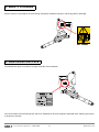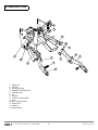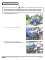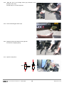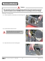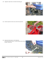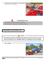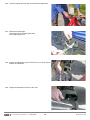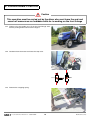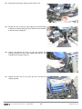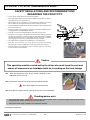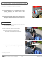
1
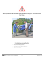
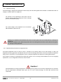
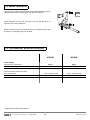
FRONT LINKAGE MX R05 MX R08 User manual Please read carefully before using MX front linkage UK 361904 AB - 1209 Original instructions Dear users, Thanks you for confidence in our product. We are sure it will give you full satisfaction. By taking a few minutes to read this manual, you will be able to obtain the best results from your MX front linkage, extend its lifespan and work in complete safety. The front linkage user manual is a very important document, please keep it with you in order to be able to use it if required. Leave it available to any other user and give it to the next owner of this front linkage. Pictures and technical information included in this document may not correspond precisely to your front linkage; but the working conditions will be the same. CONTENTS Page 1. SAFETY REGULATIONS 5 2. USAGE REGULATION 6 3. SAFETY STICKERS 7 4. IDENTIFICATION PLATE 7 5. DESCRIPTION 8 6. OPERATING POSITION 9 7. IMPLEMENT HITCHING 11 8. IMPLEMENT DISCONNECTING 13 9. FOLDED ARMS POSITION 15 10. FRONT PTO WITH TRANSMISSION SHAFT 17 11. ADDITIONAL FRONT HYDRAULIC LINE 18 12. CONTROL 18 13. MAINTENANCE 19 14. TECHNICAL SPECIFICATIONS 19 DECLARATION OF CONFORMITY 21 The operator must read this manual before using the product for the first time. Familiarise yourself with: — Safety and operating regulations. — Hitching and unhitching of the implement; — Full use of the controls. • 19, rue de Rennes • BP 83221 • F - 35690 ACIGNÉ 4 Modification reserved 1. SAFETY REGULATIONS — The tractor/loader/linkage assembly must only be driven by someone who is trained and experienced. — When the tractor is fitted with a front linkage and loader, the user has to unhitch the loader before to using the MX front linkage (please see the loader instruction book for the unhitching proceedure). — CAUTION : before using of the front loader, please check the front linkage is locked (with the hydraulic tap), and the arms are folded or removed (see chapter "folded arms position"). — Control the front linkage only from the driver's seat, or from the external remote control supplied by MX. Do not let go of the controls until the movements are complete. — The controls for operating the front linkage must be of the "continued action" type with the exception of the lift floating position which can be maintained in its position by a notching system. — Do not leave the seat before locking the controls to prevent any movement. — It is compulsory to ensure that nobody is in the area while the front linkage and tractor are in use. — The transport or elevation of persons using the front linkage is forbidden.. — Before moving with a front implement fitted, check and ensure that the tractor-front implement assembly is stable by fitting a counter weight at the rear of the tractor. This should provide 20% of the gross weight (tractor-front implement) on the rear axle of the tractor for driving and working in the best safety conditions.. — The maximum front axle safe load provided by the tractor's manufacturer must not be exceeded. — The front tyres maximum safe load provided by the tyres's manufacturer must not be exceeded. — Check regularly tyres pressure. — An implement hitched to the front linkage must be able to be lifted through the full range of linkage's movement. Any excess load preventing this movement is strictly forbidden. — Before moving, the user must ensure that the front linkage is in good working order and can be used safely. — When driving on the road with a front implement, the front linkage must always be in a raised position and the road regulations must be respected (dimensions, signalling on implement, etc.) — When driving on the road without a front implement, the front linkage must be set to the transport position (see section "Setting the front linkage to transport position") — Whenever the tractor is stopped for a short or long time, the engine must be switched off and the linkage lowered. — The tractor must never be towed from an anchoring point on the front linkage. — Regularly check the presence of safety pins and bolts. Do not replace with any other object such as nails, wire, etc. — Any activity relating to defect investigation ( diagnosis ) and / or disassembly of parts may only be undertaken by an accredited professional who shall assure his safety and the protection of the environment in which the actvity is conducted. Caution ! — The front linkage’s hydraulic circuit is designed to have a maximum service pressure of 200 bar. — never modify the hose connections — The assembly of an MX front linkage which excludes the recommendations in the MX price list in force at the purchase date, cancels the MX guarantee on all the equipment supplied. — Any modification to a section of any MX equipment (rams, arms, pivot frame, etc.) or the use of an implement or element installed on the MX front linkage from foreign origin, cancels the MX guarantee for all equipment supplied. — Use only MX original spare parts. Do not modify your MX Front linkage yourself or have another person modify them, without prior written agreement from MX. Failure to respect these regulations may make the Front linkage dangerous. MX will disclaim all responsibility in the event of damage or injury. — The guarantee is immediately invalid when the instructions for use, and the MX Front linkage maintenance schedule outlined in the "User Manual" are not observed. • 19, rue de Rennes • BP 83221 • F - 35690 ACIGNÉ 5 Modification reserved 2. USAGE REGULATION 2.1 Implement hitching The front linkage is designed for implements which comply with the hitching dimensions defined in standard ISO 730-1 for category I and ISO 730-2 for category IN. The distance of the implement's hitch points must be between 400 and 683 mm (dimension A with a linkage pin of 22 mm diameter (Ø D). The vertical height of the implement must lie between 360 and 460 mm (dimension H). Hitching of an implement with dimension less than H causes great strain on the 3rd point bar, causing it to deteriorate. Hitching an implement with a dimension greater than H can damage the front of the tractor (bonnet, front guard, etc.) during the lifting operation. 2.2 Implement/link point distance and ground work. The hitched implement must be fixed as close as possible to the hook-up points on the front linkage. In effect, the longitudinal overhang generates considerable stresses on the front linkage (lever effect). The more compact the implement fixing, the less strain there is on the equipment. Use of a compact implement also improves the lifting performances. This category of linkage is not designed for working the ground. You are strongly recommended not to fit soil engaging implements, so as to safeguard the structure of the machine. Caution ! Recommendations for fixing the implement, and working on the ground, must be strictly complied with. Any deviation from the requirements described above gives rise to a risk of serious damage, for which MX cannot be held responsible. • 19, rue de Rennes • BP 83221 • F - 35690 ACIGNÉ 6 Modification reserved 3. SAFETY STICKERS Security stickers are located on the front linkage. Keep them readable and clean, and change them if damaged. . Ref: 320005 4. IDENTIFICATION PLATE The identification plate is located on the right hand side of the headstock. The serial number and front linkage type which are indicated on this plate might be requested when requiring spare parts or technical assistance. • 19, rue de Rennes • BP 83221 • F - 35690 ACIGNÉ 7 Modification reserved 5. DESCRIPTION 9 8 13 6 12 11 2 4 7 10 3 5 1 1: 2: 3: 4: 5: 6: 7: 8: 9: 10: 11: 12: 13: Right arm Left arm Strapping spring Adjustment handle screw Linkage frame Pin Clip pin Top link retaining hook Clip Arm support bracket Locking nut Locknut Lever locknut • 19, rue de Rennes • BP 83221 • F - 35690 ACIGNÉ 8 Modification reserved 6. OPERATING POSITION Caution This operation must be carried out by the driver who must leave the seat and ensure all manoevres are forbidden while he is working on the front linkage 6.1 Choose a flat and stable area. Pull the parking brake. Turn off the engine. 6.2 Leave the cab and remove the strapping spring. 6.3 Support the L.H. arm and loosen the wing nut. Then remove the locking pin and the pin to free the arm. Tighten the wing nut on its support to prevent any loss. • 19, rue de Rennes • BP 83221 • F - 35690 ACIGNÉ 9 Modification reserved 6.4 .Slide the arm in the linkage frame (pay attention to the direction of the arm). Position the pin as shown opposite. 6.5 Insert the locking pin into the pin. 6.6 Repeat the items 6.3 to 6.6 for the right arm. Put back the strapping spring. 6.7 Open the stop valve. Closed Fermé • 19, rue de Rennes • BP 83221 • F - 35690 ACIGNÉ Open Ouvert 10 Modification reserved 7. IMPLEMENT HITCHING Caution This operation must be carried out by the driver who must leave the seat and ensure all manoevres are forbidden while he is working on the front linkage The linkage is in working position. 7.1 Hitch the implement to the ball joints of the front linkage arms. 7.2 Set the distance between the arms. This setting allows the arms to extend fully and adjust the lateral play of the implement. 7.3 Adjust the locknut to ensure the locking point. • 19, rue de Rennes • BP 83221 • F - 35690 ACIGNÉ 11 Modification reserved 7.4 .Support the top link bar and remove the locking pin. 7.5 Hitch the top link bar to the mast of the front implement. 7.6 Replace the locking pin as shown opposite. The hook therefore remains in open position when the front linkage is being used. • 19, rue de Rennes • BP 83221 • F - 35690 ACIGNÉ 12 Modification reserved 7.7 .Set the length of the top link bar to obtain the required movements from the front implement. Lock the adjustment of the bar by means of the lever locknut. Checking before work — Test the lifting by checking that the tractor/front implement combination works correctly. Particularly check the space between the top link bar and the tractor's engine bonnet. — Check that all the pins and locking pins are fitted and locked correctly. 8. IMPLEMENT DISCONNECTING Caution This operation must be carried out by the driver who must leave the seat and ensure all manoevres are forbidden while he is working on the front linkage 8.1 Lay the implement on some flat stable ground. Operate the tractor's handbrake. • 19, rue de Rennes • BP 83221 • F - 35690 ACIGNÉ 13 Modification reserved 8.2 .Free the top link bar from the mast of the front implement. 8.3 Remove the locking pin. Lift the top link bar and close the hook. Fit the locking pin back. 8.4 Loosen the adjustment screws of the arms so as to be able to unhitch the implement. 8.5 Tighten the adjustment screws of the arms. • 19, rue de Rennes • BP 83221 • F - 35690 ACIGNÉ 14 Modification reserved 9. FOLDED ARMS POSITION Caution This operation must be carried out by the driver who must leave the seat and ensure all manoevres are forbidden while he is working on the front linkage 9.1 Choose a flat and stable area. Lift up the front linkage arms. Pull the parking brake and turn off the engine. 9.2 Get down from the tractor and close the stop valve. Closed Fermé 9.3 Open Ouvert Remove the strapping spring. • 19, rue de Rennes • BP 83221 • F - 35690 ACIGNÉ 15 Modification reserved 9.4 Remove the locking pin and pin to free the R.H. arm. 9.5 Position the arm on the R.H. side support of the front linkage using the pin and the locking pin (pay attention to the direction of the arm when handling it). 9.6 Loosen and remove the wing nut from the support and vertically position the arm on the support. Maintain the arm and tighten by using the wing nut. 9.7 Repeat the items 9.4 to 9.7 for the left arm. Put back the strapping spring. • 19, rue de Rennes • BP 83221 • F - 35690 ACIGNÉ 16 Modification reserved 10. FRONT PTO WITH TRANSMISSION SHAFT * SAFETY REGULATIONS AND RECOMMENDATIONS REGARDING THE FRONT PTO — .Never start the engine with the power take-off engaged. — Before hitching the implement, check that the implement's direction of rotation is compatible with the front power take-off. — Check whether the speed and power of the implement is adapted to the power take-off. Otherwise, the implement must not be hitched and connected. — Check and adapt the length of the transmission shaft between the implement and the front power take-off. β — The universal joint of the transmission shaft must be fitted with suitable protection (complying with the standard ISO/DIS 5673-1). — Never lift or lower the front linkage with the power take-off under load. — Check the and ß angles of the implement's universal joint and the power takeoff. Adjust the top link bar so that these angles are noticeably equal (see diagram opposite). The limit value of the and ß angles depends on the type of universal joint used (refer to the universal joint manufacturer's user manual). α — The engine must be stopped for any maintenance on the implement. — Each time the power take-off is used, grease the transmission bearings beforehand as well as the sliding section of the shaft and the universal joint. — Carefully read the safety instructions for the central power take-off of the tractor (refer to the tractor's user manual). Caution This operation must be carried out by the driver who must leave the seat and ensure all manoevres are forbidden while he is working on the front linkage 10.1 Hitch the implement (refer to the section "Hitching a front implement" in this manual).. 10.2 Connect the transmission shaft to the front power take-off. The tractor engine must be turned off. 10.3 Start the front power take-off (refer to the tractor's user instructions). Checking before work — Check that the tractor - implement - transmission shaft assembly works correctly throughout the full travel of the lifting operation before starting up the power take-off. — Adapt the tractor engine speed to the implement hitched. * According to equipment • 19, rue de Rennes • BP 83221 • F - 35690 ACIGNÉ 17 Modification reserved 11. ADDITIONAL FRONT HYDRAULIC LINE * A hydraulic unit can be powered at the front of the linkage. 11.1 Connect the hydraulic hoses of the implement to the ½’ female couplings. Decompress the hydraulic system to make connecting the hoses easier. 11.2 Control the hydraulic line using the tractor's control valve or the MX compact control valve (refer to the "control" section in this manual). 12. CONTROL 12.1 With the original control valve fitted on the tractor. Refer to the user instructions for the tractor. 12.2 With the MX loader compact control valve fitted. 12.2.1 Raising and lowering the MX front linkage. Move the MX monolever forwards and backwards. 12.2.2 Controlling the auxiliary hydraulic line (depending on the fittings). Move the MX monolever to the right and left. * According to equipment • 19, rue de Rennes • BP 83221 • F - 35690 ACIGNÉ 18 Modification reserved 13. MAINTENANCE .Grease every 10 hours and after each wash (water eliminates grease) and particularly after washing with a high pressure cleaner. Check tightness of the nuts and bolts after 10 and 50 hours of operation, then every 100 hours. Before and after each use, check that there are no hydraulic leaks and that the pins and locking pins are all fitted. 14. TECHNICAL SPECIFICATIONS MX R05 MX R08 500 kg Cat. 1 and 1N 800 kg Cat. 1 and 1N 1 3/8’ - 6-spline shaft 2000 rpm 1 3/8’ - 6-spline shaft 2000 rpm Front linkage Lifting power at ball ends * Front linkage category Front PTO with transmission shaft PTO shaft profile Maximum shaft speed (rpm) * Specifications measured at 150 bar. • 19, rue de Rennes • BP 83221 • F - 35690 ACIGNÉ 19 Modification reserved DECLARATION OF CONFORMITY We manufacturer: MX 19,Rue de Rennes F - 35690 Acigné declares that the following equipment : MX R05, MX R08 front linkages comply with EC directive 2006/42 of the Council of European Parliament and of the council of 17th of May 2006 relating to machines. Acigné, 15th of December 2009. Loïc Mailleux Technical Director 19, rue de Rennes BP 83221 F - 35690 ACIGNE Tél. : +33 (0)2 99 62 52 60 Fax : +33 (0)2 99 62 50 22 e-mail : [email protected]