1
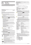
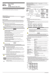
User’s
Manual
700987
Isolation logic probe
The 700987 is a Isolation logic probe for DL716.
Make sure to comply with the following safety precautions. Not complying might result in
injury or death.
WARNING
• Before using the logic probe, be sure to read the DL716's user's manual in
addition to this one as it contains necessary precautionary information relevant
to the probe's use.
CAUTION
• Applying a voltage exceeding the voltage indicated below may cause damage to
the logic probe or DL716. At a frequency above 1 kHz, damage may occur even
when the voltage is lower than this voltage.
Maximum input voltage (at a frequency of 1 kHz or below)
250 Vrms (except ACpeak is 350 V or less, DC is 250 V or less)
• Each input terminal of the isolation logic probe is isolated from all other input
terminals and the isolation logic probe is isolated from the DL716.
• Make sure to turn off DL716 before connecting or disconnecting the 26-pin
connector from the logic input connector.
• Do not stack the isolation logic probes during use. Also, allow enough space
around the probes to avoid a temperature increase inside the probes.
Logic Input Connector
Connect the logic probe to either of the logic probe input connectors (the two connectors
indicated POD A and POD B).
About the Logic probe
Use the following leads to connect to the point of measurement.
• For measuring voltages of 42 V or less
: Measurement lead, Model 366961
• For measuring voltages of 42 V or more
: Measurement lead, Model 758917
Do not alter the connecting leads. Doing so may cause the leads from satisfying the
specification.
Connecting the Logic Probe
1. Connect the measuring lead to the input terminal of the logic probe.
2. Set the input switch. The threshold level is set to 50 VAC ± 50% (Hi : 80 to 250 VAC, Lo :
0 to 20 VAC) and 6 V ± 50% (Hi : 10 to 250 VDC, Lo : 0 to 30 VDC) when set to “AC” and
“DC,” respectively.
Connecting the logic probe to the Logic Input Module
3. Turn OFF DL716.
4. Connect the end with the 26-pin connector (clamp filter with ferrite core, parts No.
A1190MN) of the logic probe to the input connector of the Logic Input Module.
5. Turn ON DL716.
To the input connector of
the Logic Input Module.
IM 700987 -01E
Yokogawa Electric Corporation
Specifications
Item
Specifications
Number of input points
8
Input format
Isolated (all bits are isolated)
Input connector
Safety terminal type (for banana plug) × 8
Input switching
Can switch between AC/DC input for each bit
Input signal display
Can confirm H/L with the LED for each bit (lights when H)
Applicable input range
During DC input: H/L detection of 10 VDC to 250 VDC
During AC input: H/L detection of AC type of 80 VAC to 250 VAC 50/60 Hz
Threshold level
During DC input: 6 V ± 50% (Hi level: 10 to 250 VDC, Lo level: 0 to 3 VDC)
During AC input: 50 VAC ± 50% (Hi level: 80 to 250 VDC, Lo level: 0 to 20 VAC)
Response time
During DC input: within 1 ms
During AC input: within 20 ms
Input impedance
approx. 100 kΩ
Maximum input voltage
(across H and L of each bit)
250 Vrms*1 (CAT I and II)
Maximum allowable common mode 250 Vrms*1 (CAT I and II)
voltage (across input terminal H or L and earth)
Maximum allowable voltage
between bits
250 Vrms*1 (CAT I and II)
Withstand voltage
(across input terminal and earth)
2000 VAC for 1 minute
Isolation resistance
(across input terminal and earth)
500 VDC, 10 MΩ or more
Fuse*2
location
max. rated voltage
max. rated current
type
standard
H side of input terminal
250 V
50 mA
time lag
VDE/SEMKO
*1 Make sure the ACpeak voltage does not exceed 350 V and the DC voltage does not exceed 250 V when the frequency is 1 kHz or less.
*2 Because the fuses used by this instrument are all inside the case, they cannot be exchanged by the user. If you believe the fuse inside the
case is blown, please contact your nearest YOKOGAWA dealer listed on the back cover of this manual.
External Dimensions
Unit: mm
117.3
45
195
The dimensional tolerance is ±3% unless otherwise specified.
(However, the tolerance of dimensions less than 10 mm is ±0.3 mm.)
IM 700987-01E