Transcript
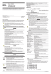
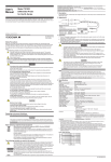
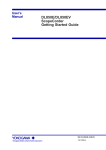
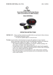
User's
Manual
YOKOGAWA ELECTRIC CORPORATION, Communication & Measurement Business Headquarters Phone: (81)-422-52-6768
9-32, Nakacho 2-chome, Musashino-shi, Tokyo, 180-8750 JAPAN
YOKOGAWA CORPORATION OF AMERICA Phone: (1)-770-253-7000 YOKOGAWA EUROPE B.V. Phone: (31)-33-4641858
Databankweg 20, 3821 AL, Amersfoort, THE NETHERLANDS
2 Dart Road, Newnan, Ga. 30265-1094, U.S.A.
YOKOGAWA ENGINEERING ASIA PTE. LTD. Phone: (65)-62419933
5 Bedok South Road, Singapore 469270, SINGAPORE
Model 701943
PB500
500 MHz Passive Probe (10:1)
1 Description
Thank you for purchasing the PB500 500 MHz Passive Probe. To ensure correct use, please read
this manual thoroughly before beginning operation. After reading the manual, keep it in a convenient
location for quick reference whenever a question arises during operation.
PB500 is a 500MHz passive probe with probe ID pin and attenuation ratio of 1/10.
This probe can be used for oscilloscopes with input impedances of 1 MΩ.
2 Appearance
yellow
green
blue violet
blue
light blue
red violet
orange
chrome yellow
Trimmer
adjustment
screw
6
2
5
1
9
3
4
• • •10 pcs
7
3rd Edition : October 2007 (YK)
All Rights Reserved, Copyright © 2005, Yokogawa Electric Corporation
10
8
IM 701943-01E
3rd Edition
Standard Accessories
Name
1 Ground lead
2 Pinchers tip
3 IC test tip
4 Ground attachment
5 Marker tip
Optional Accessories
(Sold Separately)
Name
6 Mini clip adapter
7 BNC adapter
8 Ground lead
9 Printed circuit
board adapter
10 Solder-in adapter
Part No.
B9852BD
B9852BE
B9852BF
B9852BG
B8099DT
Model
700971
700972
700973
366945
366946
3 Operation
Safety Precautions
Make sure to comply with the safety precautions mentioned hereafter when handling the probe.
Yokogawa Electric Corporation assumes no responsibility for any consequences resulting from failure
to comply with these safety precautions. Also, read the User’s Manual of the measuring instrument
thoroughly so that you are fully aware of its specifications and handling, before starting to use the
probe.
The following symbols are used on this instrument.
Warning: handle with care. Refer to the user’s manual or service manual. This symbol
appears on dangerous locations on the instrument which require special instructions for
proper handling or use. The same symbol appears in the corresponding place in the manual
to identify those instructions.
Use adequate attachment suitable for the point to measure.
Before using the probe, adjust its capacitance by tuning the trimmer.
Adjustment
1. Connect the probe connector to the input of the oscilloscope, and connect the tip of the probe to
the CAL signal output terminal.
2. Change the Time/Div and the V/Div to get the display shown below. And tune the trimmer to get
the correct waveform.
ake sure to comply with the following safety precautions in order to prevent accidents
M
such as an electric shock which impose serious health risks to the user and damage to the
instrument.
Correct Waveform
WARNING
Grounding of the measuring instrument
The protective grounding terminal of the measuring instrument must be connected to ground.
Earth cable of the probe
Make sure to connect the earth cable of the probe to the ground (grounding potential).
Handling of the passive probe
Do not touch the probe’s input terminal or the probe itself with wet hands.
Do not operated with suspected failures
If you suspect that there is damage to this probe, have it inspect by a service personnel.
Observe maximum working voltage
When the oscilloscope’s input coupling is AC, DC voltage of the same electric potential
as the probe’s input is applied to the oscilloscope’s input. Make sure not to exceed the
oscilloscope’s maximum input voltage.
Do not operate in wet/damp conditions
To avoid electric shock, do not operate this probe in wet or damp conditions.
Do not operate in explosive atmosphere
To aviod injury or fire hazard, do not operate this probe in an explosive atmosphere.
Avoid exposed circuitry
To avoid injury, remove jewelry such as rings, watches, and other metallic objects. Do not
touch exposed connections and components when power is present.
Note
Accurate measurement may not be possible near objects with strong electric fields (such as
cordless equipment, transformers, or circuits with large currents).
4 Specifications
Item
Probe length
Connector type
Input resistance
Input capacitance
Attenuation ratio
Waste Electrical and Electronic Equipment
CAUTION
Use a soft cloth to clean the dirt. Prevent damage to the probe. Avoid immersing the probe,
using abrasive cleaners, and using chemicals contains benzene or similar solvents.
Maximum input voltage
Do not apply any voltages exceeding the maximum input voltage to the probe.
WARNING
• Make sure to avoid an electric shock when connecting the probe to the object of
measurement. Do not remove the probe from the measuring instrument after the object
of measurement is connected.
• When disconnecting the probe BNC output connector, first turn OFF the power to the
circuit under measurement. Then, disconnect the probe from the high voltage parts of the
circuit under measurement.
CAUTION
Bandwidth
Waste Electrical and Electronic Equipment (WEEE), Directive 2002/96/EC
(This directive is only valid in the EU.)
This product complies with the WEEE Directive (2002/96/EC) marking requirement.
This marking indicates that you must not discard this electrical/electronic product in
domestic household waste.
Product Category
With reference to the equipment types in the WEEE directive Annex 1, this product is
classified as a “Monitoring and Control instrumentation” product.
Do not dispose in domestic household waste. When disposing products in the EU,
contact your local Yokogawa Europe B. V. office.
Rise time
Max input voltage*2
Operating temperature
Operating maximum relative
humidity
Operating altitude
Storage temperature
Matching input capacitance
(at 1/10)
Safety standards
The following symbols are used in this manual.
Improper handling or use can lead to injury to the user or damage to the instrument.
This symbol appears on the instrument to indicate that the user must refer to the
user’s manual for special instructions. The same symbol appears in the corresponding
place in the user’s manual to identify those instructions. In the manual, the symbol is
used in conjunction with the word “WARNING” or “CAUTION.”
WARNING Calls attention to actions or conditions that could cause serious or fatal injury to the
user, and precautions that can be taken to prevent such occurrences.
CAUTION Calls attentions to actions or conditions that could cause light injury to the user or
damage to the instrument or the user’s data, and precautions that can be taken to
prevent such occurrences.
Specifications
1.5 m
BNC
10MΩ ±2%
In conjunction with an oscilloscope with an input impedance of
1MΩ ±1%.
Approx. 14 pF
In conjunction with an oscilloscope with an input impedance of
1MΩ ±1%.
1/10 ±2%
In conjunction with an oscilloscope with an input impedance of
1MΩ ±1%.
DC to 500 MHz (−3 dB or less)
Subject to change depending on type of oscilloscope used.
700 ps max. (typical*1)
Subject to change depending on type of oscilloscope used.
600 V (DC + ACpeak) or 424 Vrms
5 to 40°C
80% RH at a temperature of up to 31°C, decreasing linearly to
50% RH at 40°C if the temperature is 31°C or higher.
2,000 m or less
−20 to 70°C
Approx. 15 to 25 pF
Oscilloscope measurement input capacity
Complying standards
EN61010-031
Measurement category I*3: 60 V (DC + ACpeak)
Pollution degree 2*4
*1 Typical (or average) value; not guaranteed.
*2 The maximum allowable input decreases depending on the frequency. Refer to the deleting curve
*3 This equipment is for measurement category I (CAT I). Do not use it with measurement category II (CAT II),
measurement category III (CAT III), nor measurement category IV (CAT IV).
CAT I applies to electrical equipment on a circuit that is not connected directly to the power source and
measurement performed on such wiring. CAT II applies to electrical equipment that is powered through a fixed
installation such as a wall outlet wired to a distribution board and measurement performed on such wiring. CAT
III applies to measurement of the distribution level, that is , building wiring, fixed installations. CAT IV applies to
measurement of the primary supply level, that is, overhead lines, cable systems, and so on.
*4 Pollution degree applies to the degree of adhesion of a solid, liquid, or gas which deteriorates withstand
voltage or surface resistivity. Pollution degree 2 applies to normal indoor atmospheres (with only nonconductive pollution).
Calls attention to information that is important for proper operation of the instrument.
Input voltage derating
1000
Max input voltage (V)
Note
Over Compensation Inadequate Compensation
600
100
10
13 V
0.1 M
1M
10 M
100 M
Frequency (Hz)
1000 M
IM 701943-01E