1
E7 APOGEE FLN
Technical Manual
Models: CIMR-E7U*
Document Number: TM.E7.21
Warnings and Cautions
This Section provides warnings and cautions pertinent to this product that if not heeded, may result in personal injury, fatality or equipment
damage. Yaskawa is not responsible for consequences of ignoring these instructions.
WARNING
YASKAWA manufactures component parts that can be used in a wide variety of industrial applications. The selection and application of
YASKAWA products remain the responsibility of the equipment designer or end user. YASKAWA accepts no responsibility for the way its
products are incorporated into the final system design. Under no circumstances should any YASKAWA product be incorporated into any
product or design as the exclusive or sole safety control. Without exception, all controls should be designed to detect faults dynamically
and to fail safely under all circumstances. All products designed to incorporate a component part manufactured by YASKAWA must be
supplied to the end user with appropriate warnings and instructions as to that part’s safe use and operation. Any warnings provided by
YASKAWA must be promptly provided to the end user. YASKAWA offers an express warranty only as to the quality of its products in
conforming to standards and specifications published in the YASKAWA manual. NO OTHER WARRANTY, EXPRESS OR IMPLIED, IS
OFFERED. YASKAWA assumes no liability for any personal injury, property damage, losses, or claims arising from misapplication of its
products.
WARNING
Read and understand this manual before installing, operating, or servicing this drive. All warnings, cautions, and instructions must be
followed. Qualified personnel must perform all activity. The drive must be installed according to this manual and local codes.
Do not connect or disconnect wiring while the power is on. Do not remove covers or touch circuit boards while the power is on. Do not
remove or insert the digital operator while power is on.
Before servicing, disconnect all power to the equipment. The internal capacitor remains charged even after the power supply is turned off.
Status indicator LEDs and Digital Operator display will be extinguished when the DC bus voltage is below 50 VDC. To prevent
electric shock, wait at least 5 minutes after all indicators are OFF and measure DC bus voltage level to confirm that it is at a safe level.
Do not perform a withstand voltage test on any part of the unit. This equipment uses sensitive devices and may be damaged by high
voltage.
The drive is not suitable for circuits capable of delivering more than the specified RMS symmetrical amperes. Install adequate branch short
circuit protection per applicable codes. Refer to the specification. Failure to do so may result in equipment damage and/or personal
injury.
Do not connect unapproved LC or RC interference suppression filters, capacitors, or over voltage protection devices to the output of the
drive. Capacitors may generate peak currents that exceed drive specifications.
To avoid unnecessary fault displays, caused by contactors or output switches placed between drive and motor, auxiliary contacts must be
properly integrated into the control logic circuit.
YASKAWA is not responsible for any modification of the product made by the user, doing so will void the warranty. This product must not
be modified.
Verify that the rated voltage of the drive matches the voltage of the incoming power supply before applying power.
To meet CE directives, proper line filters and proper installation are required.
Some drawings in this manual may be shown with protective covers or shields removed, to describe details. These must be replaced before
operation.
Observe Electrostatic Discharge Procedures when handling the drive and drive components to prevent ESD damage.
The attached equipment may start unexpectedly upon application of power to the drive. Clear all personnel from the drive, motor and
machine area prior to applying power. Secure covers, couplings, shaft keys, machine beds and all safety equipment before energizing
the drive.
i
Introduction
This manual explains the specifications and handling of the APOGEE FLN protocol for the Yaskawa model E7 drive. The E7 drive with the
APOGEE FLN protocol selected, connects the E7 drive to an APOGEE FLN network and facilitates the exchange of data.
This document pertains to the Yaskawa E7 drive. Additionally, in this document, the word “inverter”, “ac drive” and “drive” may be used
interchangeably.
To ensure proper operation of this product, read and understand this manual. For details on installation and operation of the E7 drive or
details on specific E7 parameters, refer to the E7 User Manual, document reference TM.E7.01. For details on E7 MODBUS
communications, refer t9 the E7 MODBUS Technical Manual, document reference TM.E7.11. All technical manuals and support files
are available on the CD supplied with the drive and for download at www.drives.com.
For more information on the APOGEE FLN protocol, please visit www.sbt.siemens.com.
GPD is a trademark of Yaskawa, Inc.
MODBUS is a registered trademark of Schneider Automation, Inc.
APOGEE FLN is a registered trademark of Siemens Building Technologies, Inc.
APOGEE Anywhere is a trademark of Siemens Building Technologies, Inc.
ii
Table of Contents
Chapter 1 Installation........................................................................... 1-1
Installation Check Sheet.....................................................................................1-3
APOGEE FLN Set-Up ........................................................................................1-5
Chapter 2 Network Connection .......................................................... 2-1
Physical Connection ...........................................................................................2-3
Chapter 3 APOGEE FLN Strategies.................................................... 3-1
Slope and Intercept Conversion .........................................................................3-3
Other Functionality .............................................................................................3-5
E7 Drive Fault Numbers .....................................................................................3-6
Chapter 4 APOGEE FLN Point Database ........................................... 4-1
APOGEE FLN Point List Summary ....................................................................4-3
Chapter 5 Cable Loss Behavior.......................................................... 5-1
Cable Loss Configuration and Behavior .............................................................5-3
Chapter 6 Mailbox Function................................................................ 6-1
Mailbox Function Points .....................................................................................6-3
Chapter 7 E7 Bypass Applications..................................................... 7-1
Bypass/Engineered Drive Parameter Settings ...................................................7-3
Appendix A Troubleshooting ................................................................. 1
Troubleshooting Check List ...................................................................................3
Installing and Configuring APOGEE FLN ..............................................................5
Wiring And Cabling ................................................................................................7
Drive Faults ...........................................................................................................8
Appendix B Hex/Dec Conversion .......................................................... 1
Hex/Dec Conversion Table ....................................................................................3
iii
This page intentionally left blank.
iv
Chapter 1 Installation
This chapter covers the initial set-up procedure for the E7 drive on an
APOGEE FLN network.
Installation Check Sheet ................................................... 1 – 3
APOGEE FLN Set-Up..........................................................1 – 5
Installation 1-1
This page intentionally left blank.
Installation 1-2
Installation Check Sheet
The following is a quick reference guide to the installation and configuration of the E7 drive with the APOGEE FLN protocol. Make a
copy of this page and check-off each item as it is completed. For detailed information please refer to the detailed sections that follow.
1:
Unpack the drive and verify that all components are present and undamaged.
2:
Connect power to the drive and verify that the drive functions. This includes running the drive in “Hand” mode from the
digital operator without the network selected or connected. Refer to the E7 User Manual for more information on
connecting and operating the drive.
3:
Remove power from the drive and wait for the charge lamp to be completely extinguished. Wait at least five additional
minutes after all indicators are off. Measure the DC bus voltage to ensure that the drive is at a safe level and completely
discharged.
4:
Connect the drive to the APOGEE FLN communication network. Refer to Chapter 2 – Network Connection for the
APOGEE FLN connection procedure.
5:
If this drive is either the first or the last device on the network, set the terminating resistor switch, S1-1, to ON. If this
device is not the first or last device on the network, set the terminating resistor switch, S1-1, to OFF. Refer to Chapter 2 –
Network Connection for details.
6:
Configure the APOGEE FLN network for the drive. Refer to the documentation included with the APOGEE FLN
Application 2721 configuration software.
7:
Set parameters b1-01, b1-02, H5-01, H5-02 and H5-08 to their appropriate values. Refer to Table 1.1 - Drive
Communication Parameter Settings on page 1-5.
Installation 1-3
This page intentionally left blank.
Installation 1-4
APOGEE FLN Set-Up
A Yaskawa Electric America, Inc. representative is responsible for proper configuration of the drive for its primary application, while a
Siemens Building Technologies, Inc. representative is responsible for field panel programming to make use of the drive’s functionality in
the building automation system. As such, there must be coordination between the Yaskawa Electric America and Siemens Building
Technologies representatives to ensure that the programming of the drive is consistent with the particular application requirements. After
verifying that the drive installation and wiring are correct, apply power to the drive. Table 1.1 below lists the parameters and their values
required for proper APOGEE FLN communication and control.
E7 Drive Parameter Settings For APOGEE FLN Communications
Table 1.1 - Drive Communication Parameter Settings
Digital Operator Display
Settings for APOGEE FLN Communication
Parameter Number
b1-01
b1-02
H5-01
H5-02
H5-08
Reference Source
Run Source
Serial Comm Adr
Serial Baud Rate
Protocol Select
2: Serial Com
2: Serial Com
Select the drive address (default = 1Fh (31 dec))
2: 4800 Baud
2: FLN(APOGEE)
CAUTION
A YEA representative should set the drive parameters to their appropriate values. Changes made to
the parameters other than what is listed in the table above can result in damaging the drive or
building equipment.
Programming The E7 Drive For APOGEE FLN
The procedure for programming the E7 drive for communication on an APOGEE FLN network is shown in the table below: Refer to the
E7 User Manual, TM.E7.01, for detailed information on using the E7 Operator.
Description
Table 1.2 - Drive Programming Procedure for APOGEE FLN
Key Operation
Digital Operator Display
-DRIVE-
Rdy
Frequency Ref
U1-01 =
Apply Power to the drive
Select Programming Menu
Press the MENU key until the display matches
the display to the right.
0.00Hz
---- ---------------------U1-02 =
0.00Hz
U1-03 =
0.00A
-ADV-
x3
** Main Menu **
---- ---------------------Programming
-ADVInitialization
---- ----------------------
Enter Programming Menu
Press the DATA ENTER key to select the
Programming Menu (A1 blinking)
A1-00 = 0
Select Language
Select Sequence Parameters
Press the UP ARROW key until Reference
Source is displayed (b1 blinking).
-ADV-
x2
Note: The item selected will blink.
Sequence
---- ----------------------
b1-01 =
2
Reference Source
Installation 1-5
Description
Table 1.2 - Drive Programming Procedure for APOGEE FLN
Key Operation
Digital Operator Display
Select Reference Command Source
Press DATA ENTER key to edit b1-01 (value
blinking). Press the UP ARROW key to change
the parameter value until the display matches the
display shown on the right. Press the DATA
ENTER key to accept the entry. “Entry Accepted”
will be displayed if successful.
-ADVReference Source
---- ----------------------
b1-01 =
Note: Since communications has not been
established, a “CALL” alarm may be generated.
Press the STOP key to clear the alarm. If
communications has not been established within
the timeout interval, the alarm will reoccur. Press
the STOP key to clear the “CALL” alarm
whenever it occurs.
2
*2*
Serial Com
“1”
Select Run Command Source
Press the UP ARROW key until Run Source is
displayed (02 blinking). Press DATA ENTER key
to edit b1-02 (value blinking). Press the UP
ARROW key to change the parameter value until
the display matches the display shown on the
right. Press the DATA ENTER key to accept the
entry. “Entry Accepted” will be displayed if
successful. If 02 is blinking, press the RESET
key to go back to the b1 menu (b1 blinking).
-ADVRun Source
---- ----------------------
b1-02 =
2
*1*
Serial Com
“1”
-ADVSelect Serial Communications Parameters
Press the UP ARROW key until Serial Com
Setup is displayed (H5 blinking).
x21
Serial Com Setup
---- ----------------------
H5-01 = 1F
Serial Comm Adr
Select FLN(APOGEE)
Press the RESET key to select an H5 parameter
(01 blinking). Press the UP ARROW key until
H5-08 is displayed (08 blinking). Press the DATA
ENTER key to edit the H5-08 parameter (value
blinking). Press the UP ARROW key to change
the parameter value until the display matches the
display shown on the right. Press the DATA
ENTER key to accept the entry. “Entry Accepted”
will be displayed if successful.
x7
-ADVProtocol Select
---- ----------------------
H5-08 = 2
FLN (APOGEE)
“0”
Note: FLN (APOGEE) must be selected prior to
setting the node address.
Installation 1-6
*2*
Description
Table 1.2 - Drive Programming Procedure for APOGEE FLN
Key Operation
Digital Operator Display
x7
Select Node Address
Press the DOWN ARROW key until parameter
H5-01 is displayed (01 blinking). Press the DATA
ENTER key to edit parameter H5-01 (value
blinking). Press the RESET or RIGHT ARROW
key to select the digit to edit. The selected digit
will blink. Press the UP ARROW or DOWN
ARROW keys to change the value of the selected
digit until the correct value is displayed. Press the
DATA ENTER key to accept the entry. Edit all
digits prior to pressing the DATA ENTER key.
“Entry Accepted” will be displayed if successful.
-ADVSerial Comm Adr
---- ----------------------
H5-01 = 1F*
(0~63)
“1F”
*This is always entered as a hexadecimal value.
Refer to the conversion chart in Appendix B for
information on converting decimal values to their
hexadecimal equivalents
Select Baud Rate of 4800 Baud
Press the UP ARROW key until parameter H5-02
is displayed (02 blinking). Press the DATA
ENTER key to edit parameter H5-02 (value
blinking). Press the UP ARROW key to change
the parameter value until the display matches the
display shown on the right. Press the DATA
ENTER key to accept the entry. “Entry Accepted”
will be displayed if successful.
-ADVSerial Baud Rate
---- ----------------------
H5-02 = 2
*3*
4800 Baud
“3”
-DRIVE** Main Menu **
---- ---------------------Operation
Select The Drive Mode
-DRIVE-
Rdy
Frequency Ref
U1-01 =
Enter The Drive Mode
0.00Hz
---- ---------------------U1-02 =
0.00Hz
U1-03 =
0.00A
Installation 1-7
This page intentionally left blank.
Installation 1-8
Chapter 2 Network Connection
This chapter discusses how to connect the E7 drive to an APOGEE FLN
network.
Physical Connection ........................................................ 2 – 3
Network Connection 2-1
This page intentionally left blank.
Network Connection 2-2
Physical Connection
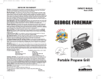
Communication on the network is half-duplex, two wire RS-485, with communication parameters fixed at 4800 baud, eight data bits, no
parity and one stop bit. The network cable is a shielded two-conductor cable.
Network Connection
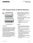
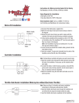
Connect a jumper between R+ and S+ and R- and S-.
Figure 2.1 – E7 Terminal Block Jumper Connections
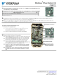
Connect the positive (+) cable lead to S+. Connect the negative (-) cable lead to S-.
Figure 2.2 – APOGEE FLN Network Cable Connections
!
Network Termination
Each APOGEE FLN network segment must be terminated on both ends to eliminate signal reflections. It is recommended that the Siemens
Building Automation BLN Trunk Terminator (PN: 538-664) be used and that the network termination switch on the E7 drive, S1-1, be set
to OFF.
Network Connection 2-3
This page intentionally left blank.
Network Connection 2-4
Chapter 3 APOGEE FLN Strategies
This chapter covers APOGEE FLN point functionality, examples of
calculating new slope and intercept values and fault numbers.
Slope & Intercept Conversion ......................................... 3 – 3
Other Functionality ........................................................... 3 – 5
E7 Drive Fault Numbers ................................................... 3 – 6
APOGEE FLN Strategies 3-1
This page intentionally left blank.
APOGEE FLN Strategies 3-2
Slope and Intercept Conversion
Several drive parameters are available for monitoring purposes. These include FREQ OUTPUT (Point 3), SPEED (Point 5), CURRENT
(Point 6), TORQUE (Point 7), POWER (Point 8), DRIVE TEMP (Point 9), KWH (Point 10), and RUN TIME (Point 12). These points can
be unbundled for monitoring or used in various global control strategies.
!
Drive Controlled Feedback
The most typical application is Supervisory Control. The sensor for the control variable (e.g., water temperature) is hard-wired to the drive
and the control device (fan) is modulated using the PI control loop that is built into the drive. The setpoint for the control variable (water
temperature set point) is unbundled and commanded by the field panel, based on some building control strategy implemented in PPCL.
When this strategy is used, the point to unbundle and command for the set point is INPUT REF 1 (Point 60). The control variable
(e.g., water temperature) can be monitored by unbundling PI FEEDBACK (Point 62). These points are provided in units of percent, where
0% and 100% correspond to the range of the sensor being used to measure the control variable. These points have default units in Hz.
If other units are required, unbundle these points with appropriate slopes and intercepts. The new intercept will be equal to the lowest value
of the desired range. The following formula lets you define a new slope and intercept in order to accomplish the unit conversion.
Range) x (Slope of Existing Point)
New Slope = (Desired (Range
of Existing Point)
- 0)Hz x (0.01) = 0.006
New Slope = (60 (100
- 0)%
Conversion Example
You are controlling water temperature from a cooling tower using the drive to control a fan. The temperature sensor has a range
of 30oF to 250oF. To unbundle the set point (INPUT REF 1), for commanding in degrees Fahrenheit, where 0 to 60 Hz is equal to
30oF to 250oF:
New Intercept = 30 (the temperature that corresponds to 0%)
Range) x (Slope of Existing Point)
New Slope = (Desired (Range
of Existing Point)
- 30)°F x (0.1) = 0.22
New Slope = (250(100
- 0)%
Formula Notes:
Desired Range = Range Maximum – Range Minimum
Range of Existing Point = Existing Range Maximum – Existing Range Minimum
APOGEE FLN Strategies 3-3
! Field Panel Controlled Feedback
In this strategy, the sensor is connected to the APOGEE FLN network at a remote location, and the control loop is executed in PPCL. The
drive speed command is passed from the field panel to the drive by commanding INPUT REF 1 (Point 60).
CAUTION
This strategy is not recommended because it means that the loop is being closed over the network.
Delays due to processor scan time and network traffic can cause control to be degraded or lost.
Damage to HVAC equipment may result.
Unbundle the FEEDBACK
To unbundle the feedback (PI FEEDBACK) for monitoring in degrees Fahrenheit:
New Intercept = 30
Range) x (Slope of Existing Point)
New Slope = (Desired (Range
of Existing Point)
- 30)°F x (0.01) = 0.022
New Slope = (250 (100
- 0)%
Formula Notes:
Desired Range = Range Maximum – Range Minimum
Range of Existing Point = Existing Range Maximum – Existing Range Minimum
APOGEE FLN Strategies 3-4
! Other Functionality
Each of the following functions must be enabled during start-up of the Drive:
Enable the drive to run
RUN ENABLE (Point 35) can be commanded to require the drive to have a physical input (Terminal S3) set before the drive can
run. This works in conjunction with CMD RUN.STOP (Point 24) or the CMD REV.STOP (Point 22). If RUN ENABLE (Point
35) is commanded ON then terminal S3 needs to be on and CMD RUN.STOP (Point 24) or CMD REV.STOP (point 22) needs to
be commanded ON for the drive to run. If, on the other hand, RUN ENABLE (Point 35) is commanded OFF, then to run the
drive CMD RUN.STOP (Point 24) or CMD REV.STOP (Point 22), is the only point that needs to be commanded ON.
Start and stop the drive
CMD RUN.STOP (Point 24) can be commanded to run the drive in the forward direction. STOP.RUN (Point 23) shows the
current status of the drive.
Change directions
CMD REV.STOP (Point 22) can be commanded to run the drive in the reverse direction. FWD.REV (Point 21) shows the current
direction of the drive rotation.
CAUTION
Improper drive direction may damage HVAC equipment if parameter b1-04, Reverse Enable, is
improperly set (b1-04 = 0).
Lock the E7 panel
Locking the panel prevents the user from using the HAND and OFF keys locally at the drive panel. LOCK PANEL (Point 33) can be
commanded to lock and unlock the panel.
Digital Outputs
MULTI OUT 1 (Point 40), MULTI OUT 2 (Point 41), and MULTI OUT 3 (Point 42) are physical digital outputs on the drive. Their
purpose depends on how the drive has been set-up. The drive can be programmed so that these points can display various limits, warnings,
and status conditions. Some examples include frequency limit, over current, and motor over temperature fault.
Loop gain
PID P GAIN (Point 63) and PID I TIME (Point 64) are the gain and integral time parameters similar to the P and I gains in the
APOGEE Terminal Equipment Controllers. The E7 drive’s PI loop is structured differently than the Siemens loop, so there is not
a one-to-one correspondence between the gains.
Reading and resetting faults
OK.FAULT (Point 93) shows the current status of the Drive. FAULT CODE (Point 17) contains the code for the most current
fault. LST FLT CODE (Point 66) contains the code for the previous fault. See table below for descriptions of the fault codes. The
drive can be reset back to OK mode by commanding RESET FAULT (Point 94) to RESET.
APOGEE FLN Strategies 3-5
E7 Drive Fault Numbers
Fault Number
1
2
3
4
5
6
7
8
9
10
11
12
13
14
15
16
17
18
19
20
21
22
23
24
25
26
27
28
29
30
31
32
33
34
35
36
37
38
39
40
41
42
43
Table 3.1 - Description of Fault Numbers
Description
DC Bus Fuse Open (PUF)
DC Bus Under Voltage (UV1)
Control Power Supply Under Voltage (UV2)
MC Answerback (UV3)
Short Circuit Fault
Ground Fault (GF)
Over Current (OC)
DC Bus Over Voltage (OV)
Overheat Fault (OH)
Overheat 1 Fault (OH1)
Motor Overload (OL1)
Inverter Overload (OL2)
Over Torque Detection 1 (OL3)
Over Torque Detection 2 (OL4)
N/A
N/A
External Fault 3 (EF3)
External Fault 4 (EF4)
External Fault 5 (EF5)
External Fault 6 (EF6)
External Fault 7 (EF7)
External Fault 8 (EF8)
Drive Fan Fault
Over Speed Fault
N/A
N/A
N/A
Output Phase Loss (LF)
Overheat 3 (OH3)
Operator Connection Fault (OPR)
Err Fault
Overheat 4 Fault (OH4)
Modbus Com Error (CE)
N/A
N/A
N/A
N/A
N/A
External Fault 0 (EF0)
PID Feedback Loss
N/A
N/A
N/A
APOGEE FLN Strategies 3-6
Chapter 4 APOGEE FLN Point
Database
This chapter shows the APOGEE FLN point database for Application
2721.
APOGEE FLN Point List Summary ................................. 4 – 3
APOGEE FLN Logical Analog Input (LAI) Summary ..... 4 – 6
APOGEE FLN Logical Analog Output (LAO) Summary . 4 – 7
APOGEE FLN Logical Digital Input (LDI) Summary ....... 4 – 8
APOGEE FLN Logical Digital Output (LDO) Summary .. 4 – 8
APOGEE FLN Point Database 4-1
This page intentionally left blank.
APOGEE FLN Point Database 4-2
APOGEE FLN Point List Summary
This database is for APOGEE FLN Application 2721 and features 97 logical points: 29 Logical Analog Inputs (LAI), 35 Logical Analog
Outputs (LAO), 19 Logical Digital Inputs (LDI) and 14 Logical Digital Outputs (LDO). These points configure, control or monitor the
operation of the Drive.
Information to consider when referencing this table:
1. Points not listed are not used in this application.
2. A single value in a column means that the value is the same in English units and in SI units.
3. Point numbers that appear in brackets, e.g. {03}, can be unbundled at the field panel.
Table 4 .1 - APOGEE FLN Application 2721 Point Number Summary
Point
Number
Point
Type
Point Name
Factory Default
(SI Units)
Engr. Units
(SI Units)
Slope
(SI Units)
Intercept
(SI Units)
On
Text
Off
Text
E7
Parameter
01
LAO
CTLR ADDRESS
31
–
1
0
–
–
H5-01
02
LAO
APPLICATION
–
–
1
0
–
–
–
{03}
LAI
FREQ OUTPUT
0
HZ
0.01
0
–
–
U1-02
{04}
LAI
PCT OUTPUT
0
PCT
0.01
0
–
–
–
{05}
LAI
SPEED
0
RPM
0.01
0
–
–
–
{06}
LAI
CURRENT
0
AMPS (A)
0.01
0
–
–
U1-03
{07}
LAI
TORQUE
0
PCT
0.1
0
–
–
–
{08}
LAI
POWER
0
KW
0.1
0
–
–
U1-08
{09}
LAI
DRIVE TEMP
0
DEG F / C
1
0
–
–
U1-41
{10}
LAI
DRIVE KWH
0
KWH
0.1
0
–
–
U1-29
U1-30
{11}
LAI
MWH
0
MWH
1
0
–
–
{12}
LAI
RUN TIME
0
HRS
1
0
–
–
U1-13
{13}
LAI
DC BUS VOLT
0
PCT
1
0
–
–
U1-07
{14}
LAI
AC OUT VOLT
0
VOLTS (V)
0.1
0
–
–
U1-06
N9-01
15
LAI
PAR N9.01
0
AMPS (A)
0.01
0
–
–
{16}
LAI
RUN TIMEX10K
0
10K HR
1
0
–
–
U1-13
{17}
LAI
FAULT CODE
0
–
1
0
–
–
U2-01
{18}
LDI
MINOR FLT
NO FLT
–
1
0
FAULT
NO FLT
U1-12 (Bit 6)
{19}
LDI
MAJOR FLT
NO FLT
–
1
0
FAULT
NO FLT
U1-12 (Bit 7)
20
LAO
OVRD TIME
1
HRS
1
0
–
–
–
{21}
LDI
FWD.REV
FWD
–
1
0
REV
FWD
U1-12 (Bit 2)
{22}
LDO
CMD REV.STOP
STOP
–
1
0
REV
STOP
–
{23}
LDI
RUN.STOP
STOP
–
1
0
RUN
STOP
U1-12 (Bit 0)
{24}
LDO
CMD RUN.STOP
STOP
–
1
0
FWD
STOP
–
{25}
LDI
ZERO SPEED
OFF
–
1
0
ON
OFF
U1-12 (Bit 1)
{26}
LDI
SPEED AGREE
NO AGR
–
1
0
AGREE
NO AGR
U1-12 (Bit 4)
{27}
LDI
DRIVE READY
NOTRDY
–
1
0
READY
NOTRDY
U1-12 (Bit 5)
{28}
LDI
LOC.REM MON
REMOTE
–
1
0
LOCAL
REMOTE
–
{29}
LDO
DAY.NGT
DAY
–
1
0
NGT
DAY
–
30
LAO
CURRENT LIM
0
AMPS (A)
0.01
0
–
–
E2-01
31
LAO
ACCEL TIME 1
0
SEC
0.1
0
–
–
C1-01
32
LAO
DECEL TIME 1
0
SEC
0.1
0
–
–
C1-02
33
LDO
LOCK PANEL
UNLOCK
–
1
0
LOCK
UNLOCK
–
35
LDO
RUN ENABLE
STOP
–
1
0
ENABLE
STOP
–
36
LAO
STALL PRE RN
90
PCT
30
0
–
–
L3-06
37
LAO
STALL PRE AC
120
PCT
1
0
–
–
L3-02
38
LAO
FREQ UP LIM
100
PCT
0.1
0
–
–
D2-01
39
LAO
FREQ LOW LIM
0
PCT
0.1
0
–
–
D2-02
{40}
LDI
MULTI OUT 1
OFF
–
1
0
ON
OFF
U1-11 (Bit 0)
{41}
LDI
MULTI OUT 2
OFF
–
1
0
ON
OFF
U1-11 (Bit 1)
APOGEE FLN Point Database 4-3
Table 4 .1 - APOGEE FLN Application 2721 Point Number Summary
Point
Number
Point
Type
Point Name
Factory Default
(SI Units)
Engr. Units
(SI Units)
Slope
(SI Units)
Intercept
(SI Units)
On
Text
Off
Text
E7
Parameter
{42}
LDI
MULTI OUT 3
OFF
–
1
0
ON
OFF
U1-11 (Bit 2)
{43}
LDI
SAFETY ILOCK
OFF
–
1
0
ON
OFF
–
{44}
LDO
MF INP 1
OFF
–
1
0
ON
OFF
–
{45}
LDO
MF INP 2
OFF
–
1
0
ON
OFF
–
{46}
LDO
MF INP 3
OFF
–
1
0
ON
OFF
–
{47}
LDO
MF INP 4
OFF
–
1
0
ON
OFF
–
{48}
LDO
MF INP 5
OFF
–
1
0
ON
OFF
–
49
LAO
JUMP FREQ 1
0
HZ
0.1
0
–
–
D3-01
50
LAO
JUMP FREQ 2
0
HZ
0.1
0
–
–
D3-02
51
LAO
JUMP FREQ 3
0
HZ
0.1
0
–
–
D3-03
52
LAO
JUMP FREQ BW
0
HZ
0.1
0
–
–
D3-04
53
LAO
NUM AUTOSTRT
0
–
1
0
–
–
L5-01
54
LAO
POWER LOSS RT
0.1
SEC
0.1
0
–
–
L2-02
55
LAO
RUN OP MODE
1
–
1
0
–
–
b1-02
56
LAO
REF OP MODE
1
–
1
0
–
–
b1-01
57
LAO
OPER DISP MD
0
–
1
0
–
–
o1-03
{58}
LDI
MF IN 1 MON
OFF
–
1
0
ON
OFF
U1-10 (Bit 2)
{59}
LDI
MF IN 2 MON
OFF
–
1
0
ON
OFF
U1-10 (Bit 3)
{60}
LAO
INPUT REF 1
0
HZ
0.01
0
–
–
–
61
LAO
INPUT REF 2
0
HZ
0.01
0
–
–
D1-02
{62}
LAI
PID FEEDBACK
0
PCT
0.01
0
–
–
U1-24
63
LAO
PID P GAIN
1
–
0.01
0
–
–
b5-02
64
LAO
PID I TIM
1
SEC
0.1
0
–
–
b5-03
65
LDO
PID MODE SEL
DISABLE
–
1
0
ENABLE
DISABLE
b5-01
{66}
LAI
LST FLT CODE
0
–
1
0
–
–
U2-02
U2-03
{67}
LAI
FREF.FLT
0
HZ
0.01
0
–
–
{68}
LAI
OUT FREQ FLT
0
HZ
0.01
0
–
–
U2-04
{69}
LAI
OUT CUR.FLT
0
AMPS (A)
0.01
0
–
–
U2-05
70
LAO
RD PARAM NUM
1
–
1
0
–
–
–
71
LAI
RD PARAM DAT
0
–
1
0
–
–
–
72
LAO
WR PARAM NUM
1
–
1
0
–
–
–
73
LAO
WR PARAM DAT
0
–
1
0
–
–
–
{74}
LDI
MF IN 3 MON
OFF
–
1
0
ON
OFF
U1-10 (Bit 4)
{75}
LAI
OUT VOLT.FLT
0
VOLTS (V)
0.1
0
–
–
U2-07
{76}
LAI
DC BUS.FLT
0
VOLTS (V)
1
0
–
–
U2-08
{77}
LAI
OUT PWR.FLT
0
KW
0.1
0
–
–
U2-09
{78}
LDI
MF IN 4 MON
OFF
–
1
0
ON
OFF
U1-10 (Bit 5)
{79}
LAI
PID DEVIATE
0
PCT
0.01
0
–
–
U1-36
80
LAO
PID I LIMIT
100
PCT
0.1
0
–
–
b5-04
b5-06
81
LAO
PID UP LIMIT
100
PCT
0.1
0
–
–
82
LAO
PID OFFS ADJ
100
PCT
0.1
-100
–
–
b5-07
83
LAO
PID PRI DYTM
0
SEC
0.1
0
–
–
b5-08
84
LAO
PID FB RMDS
0
–
1
0
–
–
b5-12
85
LAO
PID FB RMDL
0
PCT
1
0
–
–
b5-13
86
LAO
PID FB RMDT
1
SEC
0.1
0
–
–
b5-14
{87}
LAI
PID OUT CAP
0
PCT
0.01
0
–
–
U1-37
{88}
LAI
PID REF
0
PCT
0.01
0
–
–
U1-38
{89}
LAI
COMM ERR CD
0
–
1
0
–
–
U1-39
90
LDO
COMM FLT ENA
DISABLE
–
1
0
ENABLE
DISABLE
H5-05
91
LAO
CBL LOSS FRQ
0
HZ
0.01
0
–
–
D1-04
APOGEE FLN Point Database 4-4
Table 4 .1 - APOGEE FLN Application 2721 Point Number Summary
Point
Number
Point
Type
Point Name
Factory Default
(SI Units)
Engr. Units
(SI Units)
Slope
(SI Units)
Intercept
(SI Units)
On
Text
Off
Text
E7
Parameter
92
LAO
CBL LOSS TMR
2
SEC
0.1
0
–
–
H5-09
U1-12 (Bit 7)
{93}
LDI
OK.FAULT
OK
–
1
0
FAULT
OK
{94}
LDO
RESET FAULT
NO
–
1
0
RESET
NO
–
{95}
LDI
DRV COMM ERR
NO FLT
–
1
0
FAULT
NO FLT
–
{96}
LDO
EXTERNAL FLT
OK
–
1
0
FAULT
OK
–
{97}
LDI
MF IN 5 MON
OFF
–
1
0
ON
OFF
U1-10 (Bit 6)
{99}
LAI
ERROR STATUS
0
–
1
0
–
–
–
APOGEE FLN Point Database 4-5
APOGEE FLN Logical Analog Input (LAI) Summary
Table 4.2 - APOGEE FLN Application 2721 Logical Analog Input (LAI) Summary (E7 to APOGEE FLN)
Point
Number
Database Descriptor
3
4
Units
Slope
Intercept
Default
Min
Max
E7
Parameter
FREQ OUTPUT
HZ
0.01
0
0
Fmin
Fmax
U1-02
PCT OUTPUT
PCT
0.01
0
0
0
100
–
5
SPEED
RPM
1
0
0
Fmin
Fmax
–
6
CURRENT
AMPS
0.01 or 0.1
0
0
0
DriveMax
U1-03
7
TORQUE
PCT
0.1
0
0
0
300
–
8
POWER
KW
0.1
0
0
0
100
U1-08
9
DRIVE TEMP
DEG F
1
0
DrvTemp
0
4000
U1-41
0
0
0
32767
U1-29
10
DRIVE KWH
KWH
0.1 or 1
kVA Dep
11
DRIVE MWH
MWH
1
0
0
0
32767
U1-30
12
RUN TIME
HR
1
0
0
0
32767
U1-13
13
DC BUS VOLT
VOLTS
1
0
kVA Dep
0
4000
U1-07
14
AC OUT VOLT
VOLTS
1
0
0
0
kVA Dep
U1-06
15
DRV RATED AMP
AMPS
0.01 or 0.1
0
0
0
kVA Dep
N9-01
16
RUN TIME x 10K
10K HR
1
0
0
0
32767
U1-13
17
FAULT CODE
ERR CD
1
0
0
0
–
U2-01
62
PID FEEDBACK
HZ
0.01
0
0
0
40
U1-24
66
LST FLT CODE
–
1
0
0
–
–
U2-02
67
FREF.FLT
HZ
0.01
0
0
0
400
U2-03
68
OUT FREQ.FAULT
HZ
0.01
0
0
0
400
U2-04
69
OUT CUR.FLT
AMPS
0.1
0
0
0
kVA Dep
U2-05
71
RD PARAM DAT
–
1
0
–
–
–
–
75
OUT VOLT.FLT
VOLTS
0.1
0
0
0
400
U2-07
76
DC BUS.FLT
VOLTS
1
0
0
0
4000
U2-08
77
OUT PWR.FLT
KW
0.1
0
0
0
400
U2-09
79
PID DEVIATE
PCT
0.01
0
0
0
400
U1-36
87
PID OUT CAP
PCT
0.01
0
0
0
40
U1-37
88
PID REF
PCT
0.01
0
0
0
40
U1-38
89
COMM ERR CD
–
1
0
0
0
4000
U1-39
99
ERROR STATUS
–
1
0
0
0
255
–
APOGEE FLN Point Database 4-6
APOGEE FLN Logical Analog Output (LAO) Summary
Table 4.3 - APOGEE FLN Application 2721 Logical Analog Output (LAO) Summary (APOGEE FLN to E7)
Point
Number
Database Descriptor
Units
Slope
Intercept
1
CTLR ADDRESS
–
1
2
APPLICATION
–
1
20
OVRD TIME
HR
30
CURRENT LIMIT
A
31
ACCEL TIME
SEC
0.1
0
10
0
32767
C1-01
32
DECEL TIME
SEC
0.1
0
10
0
32767
C1-02
36
STALL PRE RN
PCT
30
0
90
0
170
L3-06
37
STALL PRE AC
PCT
1
0
120
0
200
L3-02
38
FREQ UP LIM
PCT
0.1
0
100
0
110
D2-01
39
FREQ LOW LIM
PCT
0.1
0
0
0
110
D2-02
49
JUMP FREQ 1
HZ
0.1
0
0
0
400
D3-01
50
JUMP FREQ 2
HZ
0.1
0
0
0
400
D3-02
51
JUMP FREQ 3
HZ
0.1
0
0
0
400
D3-03
52
JUMP FREQ BW
HZ
0.1
0
1
0
20
D3-04
53
NUM AUTOSTRT
–
1
0
0
0
10
L5-01
54
PWR LOSS RT
SEC
0.1
0
0
0
25.5
L2-02
55
RUN OP MODE
–
1
0
1
0
3
b1-02
56
REF OP MODE
–
1
0
1
0
3
b1-01
57
OPER DISP MD
–
1
0
0
0
32767
o1-03
60
INPUT REF 1
HZ
0.01
0
0
0
400
–
61
INPUT REF 2
HZ
0.01
0
0
0
400
D1-02
63
PID P GAIN
–
0.01
0
1
0
25
b5-02
64
PID I TIME
SEC
0.1
0
1
0
360
b5-03
Max
E7
Parameter
0
99
H5-01
0
32767
–
8
1
255
–
kVA Dep
0
1500
E2-01
Default
Min
0
31
0
2721
1
0
0.01 or 0.1
0
70
RD PARAM NUM
–
1
0
–
–
–
–
72
WR PARAM NUM
–
1
0
–
–
–
–
73
WR PARAM DAT
–
1
0
–
–
–
–
80
PID I LIMIT
PCT
0.1
0
100
0
100
b5-04
81
PID UP LIM
PCT
0.1
0
100
0
100
b5-06
82
PID OFFS ADJ
PCT
0.1
-100
0
0
200
b5-07
83
PID PRI DYTM
SEC
0.01
0
0
0
10
b5-08
84
PID FB RMDS
–
1
0
0
0
2
b5-12
85
PID FB RMDL
–
1
0
1
0
2
b5-13
86
PID FB RMDT
SEC
0.1
0
1
0
25.5
b5-14
91
CBL LOSS FRQ
HZ
0.01
0
0
0
400
D1-04
92
CBL LOSS TMR
SEC
0.1
0
2
0
3600
H5-09
APOGEE FLN Point Database 4-7
APOGEE FLN Logical Digital Input (LDI) Summary
Point
Number
Table 4.4 - APOGEE FLN Application 2721 Logical Digital Input (LDI) Summary (E7 to APOGEE FLN)
Off (0)
On (1)
E7
Database Descriptor
Slope
Intercept
Default
Min
Max
State
State
Parameter
18
MINOR FLT
1
0
0
0
1
NO FLT
FAULT
19
MAJOR FLT
1
0
0
0
1
NO FLT
FAULT
U1-12 (Bit 6)
U1-12 (Bit 7)
21
FWD.REV
1
0
0
0
1
FWD
REV
U1-12 (Bit 2)
23
RUN.STOP
1
0
0
0
1
STOP
RUN
U1-12 (Bit 0)
25
ZERO SPEED
1
0
0
0
1
OFF
ON
U1-12 (Bit 1)
26
SPEED AGREE
1
0
0
0
1
NO AGR
AGREE
U1-12 (Bit 4)
27
DRIVE READY
1
0
0
0
1
NOTRDY
READY
U1-12 (Bit 5)
28
HND/AUTO MON
1
0
0
0
1
REMOTE
LOCAL
–
40
MULTI OUT 1
1
0
0
0
1
OFF
ON
U1-11 (Bit 0)
41
MULTI OUT 2
1
0
0
0
1
OFF
ON
U1-11 (Bit 1)
42
MULTI OUT 3
1
0
0
0
1
OFF
ON
U1-11 (Bit 2)
43
SAFETY ILOCK
1
0
0
0
1
OFF
ON
–
58
MF IN 1 MON
1
0
0
0
1
OFF
ON
U1-10 (Bit 2)
59
MF IN 2 MON
1
0
0
0
1
OFF
ON
U1-10 (Bit 3)
74
MF IN 3 MON
1
0
0
0
1
OFF
ON
U1-10 (Bit 4)
78
MF IN 4 MON
1
0
0
0
1
OFF
ON
U1-10 (Bit 5)
93
OK.FAULT
1
0
0
0
1
NO FLT
FAULT
U1-12 (Bit 7)
95
DRV COMM ERR
1
0
0
0
1
NO FLT
FAULT
–
97
MF IN 5 MON
1
0
0
0
1
OFF
ON
U1-10 (Bit 6)
APOGEE FLN Logical Digital Output (LDO) Summary
Point
Number
Table 4.5 - APOGEE FLN Application 2721 Logical Digital Output (LDO) Summary (APOGEE FLN to E7)
Off (0)
On (1)
E7
Database Descriptor
Slope
Intercept
Default
Min
Max
State
State
Parameter
22
CMD REV.STOP
1
0
0
0
1
STOP
REV
–
24
CMD RUN.STOP
1
0
0
0
1
STOP
FWD
–
29
DAY.NGT
1
0
0
0
1
DAY
NGT
–
33
LOCK PANEL
1
0
0
0
1
UNLOCK
LOCK
–
35
RUN ENABLE
1
0
0
0
1
STOP
ENABLE
–
44
MF INP 1
1
0
0
0
1
OFF
ON
–
45
MF INP 2
1
0
0
0
1
OFF
ON
–
46
MF INP 3
1
0
0
0
1
OFF
ON
–
47
MF INP 4
1
0
0
0
1
OFF
ON
–
48
MF INP 5
1
0
0
0
1
OFF
ON
–
65
PID MODE SL
1
0
0
0
1
OFF
ON
b5-01
90
COMM FLT ENA
1
0
1
0
1
DISABLE
ENABLE
H5-05
94
RESET FAULT
1
0
0
0
1
RESET
OK
–
96
EXTERNAL FLT
1
0
0
0
1
FAULT
OK
–
APOGEE FLN Point Database 4-8
Chapter 5 Cable Loss Behavior
This chapter describes the configurable cable loss feature of the E7 drive.
Cable Loss Configuration and Behavior ........................ 5 – 3
Cable Loss Behavior 5-1
This page intentionally left blank.
Cable Loss Behavior 5-2
Cable Loss Configuration and Behavior
This section describes the configurable cable loss feature of the drive. This feature offers a user maximum flexibility in determining the
drive’s response to a loss of communication.
Drive Behavior At Loss of Communication
After some interval without receipt of a message, the drive can be configured to respond in one of the following manners:
Continue at last speed
Continue at last speed with Alarm
Continue at preset speed
Ramp to Stop with EF0 fault
Coast to Stop with EF0 fault
Emergency Stop with EF0 fault
APOGEE FLN Points
Three APOGEE FLN points are used to select the desired behavior:
POINT 92 – CBL LOSS TMR
POINT 91 – CBL LOSS FRQ
POINT 90 – COMM FLT ENA
Table 5.1 - Cable Loss Behavior Summary
Behavior
CBL LOSS TMR
(Point 92)
H5-04
CBL LOSS FRQ
(Point 91)
COMM FLT ENA
(Point 90)
Decelerate to stop (stop time in C1-02) EF0 Fault
0
Timeout Interval
X
On
Coast to stop EF0 Fault
1
Timeout Interval
X
On
Emergency stop (stop time in C1-09) EF0 Fault
2
Timeout Interval
X
On
Continue at last speed
3
0
X
X
Continue at last speed with Alarm
3
Timeout Interval
X
On
Continue at preset speed with Alarm
4
Timeout Interval
Preset Speed
On
Notes:
1.
Communication must first be established and then lost for these features to function as described. If a drive is powered-up without a cable
connected or with the master controller offline, a communications timeout does not occur.
2.
For modes which describe the drive running after a communications timeout, a run command must have been issued (RUN ENABLE (Point 35)
= ‘On’ and either CMD RUN.FWD (Point 22) = ‘On’ or CMD RUN.REV (Point 24) = ‘On’) prior to loss of communications. For safety
purposes, the drive will not automatically restart from a stopped condition. If a user requires the drive to restart automatically, additional
external wiring is required to accomplish this (consult factory).
Upon expiration of the communications timeout interval, the FAULT LED lights and remains lit until communication is restored.
Continue at Last Speed
In this mode, CBL LOSS TMR (POINT 92) is set to 0, disabling the cable loss feature. The other two settings CBL LOSS FRQ
(POINT 91) and COMM FLT ENA (POINT 90) are ignored. If communication is lost, the drive simply maintains its last
commanded state. The drive will not display an alarm or fault to indicate it has lost communication. This behavior can also be
achieved by setting parameter H5-04 to “3”. The drive will display an alarm and continue running. For this specific condition,
the COMM FLT ENA(POINT 90) must be enabled and CBL LOSS TMR (POINT 91) should be set to something other than 0.
Continue at Preset Speed
In this mode, CBL LOSS TMR (POINT 92) is set to the desired interval, CBL LOSS FRQ (POINT 91) is set to the desired preset speed and
H5-04 is set to “4”. If the time between messages exceeds the timeout interval, the drive’s speed command, INPUT REF 1, (Point 60) is set
to the CBL LOSS FRQ (POINT 91) and the drive continues running at this new speed. COMM FLT ENA (POINT 90) must be set to ‘On’.
Cable Loss Behavior 5-3
Stop
COMM FLT ENA (POINT 90) must be set to ‘On’. In this mode, CBL LOSS TMR (POINT 92) is set to the desired interval and
parameter H5-04 is set to a value of 0,1 or 2. If the time between messages exceeds the timeout interval, the drive’s speed
command, INPUT REF 1, (Point 60) is set to 0. The stopping method is determined by the setting of H5-04. An EF0 drive fault
will be set.
H5-04 = 0 selects Ramp to Stop. The deceleration time or the slope of the ramp is determined by the setting of drive
parameter C1-02.
H5-04 = 1 selects Coast to Stop. The drive does not attempt to control the rate of deceleration.
H5-04 = 2 selects Emergency or Fast Stop. The deceleration time is determined by the setting of drive parameter C1-09.
CAUTION
The behavior of the drive at cable loss is controlled by parameter H5-04. This drive parameter works
with the points as described in the table above to determine how the drive will respond to a cable
loss. If the cable loss fault is disabled, the drive will continue in its last state, if running the drive
will continue to run at the last commanded frequency.
Fault (EF0)
In this mode, CBL LOSS TMR (POINT 92) is set to the desired interval, COMM FLT ENA (POINT 90) or is set to ‘On’ and either
CMD RUN.FWD (Point 22) or CMD RUN.REV (Point 24) is set to ‘On’. If the time between messages exceeds the timeout
interval, an ‘EF0’ fault is declared and the drive stops. The stopping method is controlled by the setting of H5-04 and is described
above. CBL LOSS FRQ (POINT 91) is ignored.
Cable Loss Behavior 5-4
Chapter 6 Mailbox Function
This chapter defines the APOGEE FLN points that read and write E7 drive
parameters.
Mailbox Function Points .................................................. 6 – 3
Mailbox Function 6-1
This page intentionally left blank.
Mailbox Function 6-2
Mailbox Function Points
! Reading a Drive Parameter
Two points are defined for reading any drive parameter:
#70 Specifies the parameter to be read from
#71 Reports the value of the parameter specified in Point #70
When this point is read, it retrieves data from the parameter and sends it to the controller
Example:
Entering a value of 387 (183 hex) in Point #70 specifies drive parameter b1-04. Reading Point #71 returns the current setting of
parameter b1-04 to the controller
Writing to a Drive Parameter
Two points are defined for writing to any drive parameter:
#72 Specifies the parameter to be written to
#73 Entry location of the value to be written to the parameter specified in Point #72
When this point is written to, it will write the value to the drive. An enter or accept command does not need to be sent for the
data to be taken by the drive. The behavior of the write is the same as with the digital operator. If the drive is running, there are a
limited number of drive parameters that can be written to.
Example:
Entering a value of 387 (183 hex) in Point #72 specifies drive parameter b1-04. Commanding Point #73 to a value of 1 enables the drive
for reverse run.
Refer to the either the E7 User’s Manual or the E7 Programming Manual for MODBUS communication set-up and configuration. The
E7 User’s Manual and the E7 Programming Manual provide references to E7 drive parameters and their respective drive addresses and
functions.
Mailbox Function 6-3
This page intentionally left blank.
Mailbox Function 6-4
Chapter 7 E7 Bypass Applications
This chapter lists the typical parameters for a bypass/engineered drive.
Bypass/Engineered Drive Parameter Settings................ 7 – 3
E7 Bypass Applications 7-1
This page intentionally left blank.
E7 Bypass Applications 7-2
Bypass/Engineered Drive Parameter Settings
For many applications, the drive is integrated into a bypass or engineered package. This type of package typically features an enclosure
with contactors that allow the user to run the motor from line power (bypass mode) or from the drive (drive mode). This package also
provides the flexibility for interfacing normally closed safety interlocks (fire status, freeze status, vibration sensors, etc.) which stop the
drive if the contacts open.
Typical Parameter Settings
A bypass/engineered drive is supplied with a list of parameters and their default values. Use the table below to record any parameter
modifications for this particular application.
Table 7.1 - Typical Bypass/Engineered Drive Parameters
Parameter
Number
Bypass Settings
Default
Description
User
E1-01
Input Voltage (VAC) – Parameter defaults dependent on drive model
E1-05
Maximum Output voltage (VAC) – Parameter defaults dependent on drive model
E2-01
Motor Rated Current (FLA) (A) – Parameter defaults dependent on drive model
T1-02
Motor Rated Power (kW) – Parameter defaults dependent on motor
T1-04
Motor Rated Current (FLA) (A) – Parameter defaults dependent on motor
A1-01
2
Parameter Access Level (2 – Advanced)
b1-01
Frequency Reference Source (dependent on options specified)
b1-02
Command Source (dependent on options specified)
b1-03
0
Stopping Method (0 – Ramp to Stop) (ramp slope set by C1-02)
b1-04
1
Reverse Operation (1 – Disabled)
b1-07
1
Local/Remote RUN Selection (1 – Accept External RUN)
b1-08
1
RUN Command During Programming (1 – Enabled)
b1-12
HAND Mode Frequency Reference Selection (Operator Keypad)
b2-02
50%
b2-03
5.0 sec
b2-09
0.0A
b3-01
1
Speed Search Select (1 – Enabled (Speed Estimated))
b8-01
1
Energy Conservation Control Select (1 – Enabled)
C1-01
60.0 sec
Acceleration Time
C1-02
60.0 sec
Deceleration Time
d1-01
10.0 Hz
Frequency Reference 1 (HAND Mode) (see H1-03)
d1-02
20.0 Hz
Frequency Reference 2 (HAND Mode) (see H1-03)
E1-01
E1-03
DC Injection Braking Current (50%)
DC Injection Braking Current @ Start (5.0sec)
Motor Preheat Current
Input Voltage– Parameter defaults dependent on drive model
7
E1-05
V/F Pattern Select
Output Voltage– Parameter defaults dependent on drive model
F6-01
3
Operation After Communication Loss (3 – Alarm Only)
H1-01
6A
H1-02
6
H1-03
6C
Terminal S5 Function (Frequency Reference 2 (N.O.))
H1-04
20
Terminal S6 Function (External Fault (N.O.))
H1-05
8
Terminal S7 Function (External Base Block (N.O.))
H2-02
3B
Terminal S3 Function (Drive Enable)
Terminal S4 Function (Local /Remote Select)
Terminal M3-M4 (Command Source – Serial)
E7 Bypass Applications 7-3
Table 7.1 - Typical Bypass/Engineered Drive Parameters
Bypass Settings
Parameter
Number
Default
H3-08
2
Terminal A2 (0–10vdc)
H3-09
2
Terminal A2 (Auxiliary Frequency Reference)
H3-12
0.3 sec
H3-13
0
Master Frequency Reference Terminal Select (0 – Terminal A1)
L2-01
2
Momentary Power Loss Detection Select (2 – CPU power active (UV fault not detected))
L4-05
1
Frequency Reference Loss Detection Select (1 – RUN @ 80% of frequency prior to loss)
L5-01
10
Number of Re-Start Attempts
L5-03
600.0 sec
L6-01
6
L6-02
15%
L6-03
10.0 sec
L8-03
4
L8-11
300 sec
L8-19
20%
o2-01
0
Local/Remote Key Function (0 - Disabled)
o2-02
0
OFF Key Function (0 – Disabled)
o2-05
1
Frequency Reference Setting Method select (1 – Enabled (Enter key Not Required from Keypad)
o2-08
1
Cumulative Operation Time Select (1 – Time @ RUN)
o3-02
1
Keypad COPY Function Select (1 – Enabled)
Description
User
Analog Input Filter Time
Maximum Restart Time After Fault
Torque Detection Select (6 – No Load Detect and Alarm)
Torque Detection Level (% of drive rated current)
Torque Detection Time
Overheat Pre-Alarm Operation Select (4 – Alarm and Reduce)
Heatsink cooling Fan Operation Delay Time
Overheat Frequency Reference Reduction Level
E7 Bypass Applications 7-4
Appendix A Troubleshooting
This appendix describes the steps necessary to troubleshoot the E7 drive
communicating on an APOGEE FLN network.
Troubleshooting Check List ............................................ A - 3
Installing and Configuring APOGEE FLN ...................... A – 5
Wiring And Cabling ......................................................... A – 7
Drive Faults ...................................................................... A – 8
Troubleshooting A-1
This page intentionally left blank.
Troubleshooting A-2
Troubleshooting Check List
1:
2:
Connect power to the drive and verify that the drive operates correctly in HAND mode from the digital operator without
being connected to the network. Record the drive model number and “spec” number at this time:
Model Number:
CIMR-E7U ___ ___ ___ ___
(e.g. CIMR-E7U20P4)
”SPEC” Number:
___ ___ ___ ___ ___ ___
(e.g. 20P41A)
Record the control board part number:
ETC - ___ ___ ___ ___ ___ ___ - ___ ___ ___ ___ ___
3:
All network devices have unique addresses and drives are addressed between 0-99 (0-63 hex).
Drive address:
4:
(e.g. ETC-618021-S2012)
____________
The Run/Stop command source parameter, b1-02 is set correctly.
b1-02: ____________
5:
The Speed Command source parameter, b1-01, is set correctly.
b1-01: ____________
6:
The correct cable type is used:
Mfg: ____________________ P/N: ____________________
7:
All cable connections are correct per device schematic and are secure.
8:
All cables have been checked for continuity. There are no breaks or shorts.
9:
The network is correctly terminated.
10:
The shield is continuous throughout the network and is properly grounded on each end.
11:
The network cable is routed away from any high voltage cable(s) or source(s).
12:
All network devices have been tested for conformance with the APOGEE FLN specification.
Troubleshooting A-3
This page intentionally left blank.
Troubleshooting A-4
Installing and Configuring APOGEE FLN
The following is a short guide to troubleshooting the APOGEE FLN installation and configuration. It highlights some of the most common
issues faced when diagnosing and correcting issues associated with the startup and operation of an E7 drive with APOGEE FLN building
automation network. While most of the information is centered on the application of the drive, the guidelines presented are applicable in
most APOGEE FLN networks.
Diagnosis of network fault issues will typically fall into three categories: 1: Installation/set-up of APOGEE FLN, 2: wiring and cabling
issues, and 3: network configuration/diagnostics. Each of these areas will be discussed after to help resolve common problems associated in
APOGEE FLN network troubleshooting.
Drive Operates Correctly Without Network Enabled
Before programming the drive for APOGEE FLN communication, verify that the drive functions properly. Refer to the E7 User Manual
for information on the drive’s installation and operation.
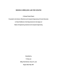
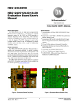
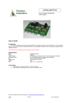
Network Cable Is Connected Correctly And Securely
Connect a jumper between R+ and S+ as well as R- and S-. Connect network cable to terminals S+ and S+.
Black (-)
Red (+)
Shield
Figure A.1 – E7 APOGEE FLN Network Connections
Run/Stop Operation Parameter Is Set Correctly
The run/stop operation parameter needs to be set for “Serial Com”.
Table A.1 - Run/Stop Operation Parameter
Parameter Number
Setting Choices
0
b1-02
Setting Descriptions
Operator
1
Terminals
2
Serial Com FLN (APOGEE)
3
Option PCB
Troubleshooting A-5
! Speed Command Operation Parameter Is Set Correctly
The speed command operation parameter needs to be set for “Serial Com”.
Table A.2 - Speed Command Operation Parameter
Parameter Number
b1-01
Setting Choices
Setting Descriptions
0
Operator
1
Terminals
2
Serial Com (APOGEE FLN)
3
Option PCB
Correct and Unique Network Address
Each device on an APOGEE FLN network requires its own unique address. The drive also needs to be programmed to accept the APOGEE
FLN protocol.
Table A.3 - Serial Communication Device Address Parameter
Parameter Number
Setting Range
H5-01
0 to 63 hex
H5-08
0 to 2
Troubleshooting A-6
Setting Description
Serial communication device address
2: FLN (APOGEE)
Wiring And Cabling
! The network cable is the correct type
Table A.4 - APOGEE FLN Cable Specifications
Specification
Cable Configuration
Description
Twisted Shielded Pair
Gauge
18-20 AWG (Solid or Stranded)
Wire Lay
Minimum 6 twists per foot
Shields
100% foil with drain wire
NEC Type
UL Type CMP
Temperature
60oC or higher
Cable Lengths Are Within Specified Limits
Cable lengths cannot exceed 500 feet at 4800 baud.
The Network is Terminated Correctly
Each APOGEE FLN network segment must be terminated on both ends to eliminate signal reflections. It is recommended that the Siemens
Building Automation BLN Trunk Terminator (PN: 538-664) be used and that the network termination switch on the E7 drive, S1-1, be set
to OFF.
Shield Is Continuous And Both Ends Of The Shield Are Grounded
As each drive is daisy-chained to the next, twist together the shields of the adjoining cables. Do not connect the shield at each drive.
The continuous shield should then be single-point grounded at the field panel.
Cable Is Routed Correctly
Route the cable away from all power and high frequency lines. Routing within a separate conduit is preferred.
Troubleshooting A-7
Drive Faults
! Communications Fault
Table A.6 - Drive Faults
Fault
CE
!
Description
Communication Error
Cause
Connection is broken or master has
stopped communicating
Corrective Action
Check all connections
Verify all APOGEE FLN software configurations
E7 Drive Faults
Fault Number
1
2
3
4
5
6
7
8
9
10
11
12
13
14
15
16
17
18
19
20
21
22
23
24
25
26
27
28
29
30
31
32
33
34
35
36
37
38
39
40
41
42
43
Table A.7 - Description of Fault Numbers
Description
DC Bus Fuse Open (PUF)
DC Bus Under Voltage (UV1)
Control Power Supply Under Voltage (UV2)
MC Answerback (UV3)
Short Circuit Fault
Ground Fault (GF)
Over Current (OC)
DC Bus Over Voltage (OV)
Overheat Fault (OH)
Overheat 1 Fault (OH1)
Motor Overload (OL1)
Inverter Overload (OL2)
Over Torque Detection 1 (OL3)
Over Torque Detection 2 (OL4)
N/A
N/A
External Fault 3 (EF3)
External Fault 4 (EF4)
External Fault 5 (EF5)
External Fault 6 (EF6)
External Fault 7 (EF7)
External Fault 8 (EF8)
Drive Fan Fault
Over Speed Fault
N/A
N/A
N/A
Output Phase Loss (LF)
Overheat 3 (OH3)
Operator Connection Fault (OPR)
Err Fault
Overheat 4 Fault (OH4)
Modbus Com Error (CE)
N/A
N/A
N/A
N/A
N/A
External Fault 0 (EF0)
PID Feedback Loss
N/A
N/A
N/A
Troubleshooting A-8
Appendix B Hex/Dec Conversion
This appendix describes the decimal to hexadecimal conversion.
Hex/Dec Conversion Table .............................................. B - 3
Hex/Dec Conversion B-1
This page intentionally left blank.
Hex/Dec Conversion B-2
Hex/Dec Conversion Table
Hex
Dec
Hex
Dec
0
1
2
3
4
5
6
7
8
9
A
B
C
D
E
F
10
11
12
13
14
15
16
17
18
19
1A
1B
1C
1D
1E
1F
20
21
22
23
24
25
26
27
28
29
2A
2B
2C
2D
2E
2F
30
31
32
33
0
1
2
3
4
5
6
7
8
9
10
11
12
13
14
15
16
17
18
19
20
21
22
23
24
25
26
27
28
29
30
31
32
33
34
35
36
37
38
39
40
41
42
43
44
45
46
47
48
49
50
51
34
35
36
37
38
39
3A
3B
3C
3D
3E
3F
40
41
42
43
44
45
46
47
48
49
4A
4B
4C
4D
4E
4F
50
51
52
53
54
55
56
57
58
59
5A
5B
5C
5D
5E
5F
60
61
62
63
64
65
66
67
52
53
54
55
56
57
58
59
60
61
62
63
64
65
66
67
68
69
70
71
72
73
74
75
76
77
78
79
80
81
82
83
84
85
86
87
88
89
90
91
92
93
94
95
96
97
98
99
100
101
102
103
Table B.1 – Hex/Dec Conversions
Hex
Dec
68
69
6A
6B
6C
6D
6E
6F
70
71
72
73
74
75
76
77
78
79
7A
7B
7C
7D
7E
7F
80
81
82
83
84
85
86
87
88
89
8A
8B
8C
8D
8E
8F
90
91
92
93
94
95
96
97
98
99
9A
9B
104
105
106
107
108
109
110
111
112
113
114
115
116
117
118
119
120
121
122
123
124
125
126
127
128
129
130
131
132
133
134
135
136
137
138
139
140
141
142
143
144
145
146
147
148
149
150
151
152
153
154
155
Hex/Dec Conversion B-3
Hex
Dec
Hex
Dec
9C
9D
9E
9F
A0
A1
A2
A3
A4
A5
A6
A7
A8
A9
AA
AB
AC
AD
AE
AF
B0
B1
B2
B3
B4
B5
B6
B7
B8
B9
BA
BB
BC
BD
BE
BF
C0
C1
C2
C3
C4
C5
C6
C7
C8
C9
CA
CB
CC
CD
CE
CF
156
157
158
159
160
161
162
163
164
165
166
167
168
169
170
171
172
173
174
175
176
177
178
179
180
181
182
183
184
185
186
187
188
189
190
191
192
193
194
195
196
197
198
199
200
201
202
203
204
205
206
207
D0
D1
D2
D3
D4
D5
D6
D7
D8
D9
DA
DB
DC
DD
DE
DF
E0
E1
E2
E3
E4
E5
E6
E7
E8
E9
EA
EB
EC
ED
EE
EF
F0
F1
F2
F3
F4
F5
F6
F7
F8
F9
FA
FB
FC
FD
FE
FF
100
208
209
210
211
212
213
214
215
216
217
218
219
220
221
222
223
224
225
226
227
228
229
230
231
232
233
234
235
236
237
238
239
240
241
242
243
244
245
246
247
248
249
250
251
252
253
254
255
256
E7 APOGEE® FLN
YASKAWA ELECTRIC AMERICA, INC.
Drives Division
16555 W. Ryerson Rd., New Berlin, WI 53151, U.S.A.
Phone: (800) YASKAWA (800-927-5292) Fax: (262) 782-3418
Internet: http://www.drives.com
YASKAWA ELECTRIC AMERICA, INC.
Chicago-Corporate Headquarters
2121 Norman Drive South, Waukegan, IL 60085, U.S.A.
Phone: (800) YASKAWA (800-927-5292) Fax: (847) 887-7310
Internet: http://www.yaskawa.com
MOTOMAN INC.
805 Liberty Lane, West Carrollton, OH 45449, U.S.A.
Phone: (937) 847-6200 Fax: (937) 847-6277
Internet: http://www.motoman.com
YASKAWA ELECTRIC CORPORATION
New Pier Takeshiba South Tower, 1-16-1, Kaigan, Minatoku, Tokyo, 105-0022, Japan
Phone: 81-3-5402-4511 Fax: 81-3-5402-4580
Internet: http://www.yaskawa.co.jp
YASKAWA ELETRICO DO BRASIL COMERCIO LTDA.
Avenida Fagundes Filho, 620 Bairro Saude Sao Paolo-SP, Brasil CEP: 04304-000
Phone: 55-11-5071-2552 Fax: 55-11-5581-8795
Internet: http://www.yaskawa.com.br
YASKAWA ELECTRIC EUROPE GmbH
Am Kronberger Hang 2, 65824 Schwalbach, Germany
Phone: 49-6196-569-300 Fax: 49-6196-888-301
MOTOMAN ROBOTICS AB
Box 504 S38525, Torsas, Sweden
Phone: 46-486-48800 Fax: 46-486-41410
MOTOMAN ROBOTEC GmbH
Kammerfeldstrabe 1, 85391 Allershausen, Germany
Phone: 49-8166-900 Fax: 49-8166-9039
YASKAWA ELECTRIC UK LTD.
1 Hunt Hill Orchardton Woods Cumbernauld, G68 9LF, Scotland, United Kingdom
Phone: 44-12-3673-5000 Fax: 44-12-3645-8182
YASKAWA ELECTRIC KOREA CORPORATION
Paik Nam Bldg. 901 188-3, 1-Ga Euljiro, Joong-Gu, Seoul, Korea
Phone: 82-2-776-7844 Fax: 82-2-753-2639
YASKAWA ELECTRIC (SINGAPORE) PTE. LTD.
Head Office: 151 Lorong Chuan, #04-01, New Tech Park Singapore 556741, Singapore
Phone: 65-282-3003 Fax: 65-289-3003
TAIPEI OFFICE (AND YATEC ENGINEERING CORPORATION)
10F 146 Sung Chiang Road, Taipei, Taiwan
Phone: 886-2-2563-0010 Fax: 886-2-2567-4677
YASKAWA JASON (HK) COMPANY LIMITED
Rm. 2909-10, Hong Kong Plaza, 186-191 Connaught Road West, Hong Kong
Phone: 852-2803-2385 Fax: 852-2547-5773
BEIJING OFFICE
Room No. 301 Office Building of Beijing International Club,
21 Jianguomanwai Avenue, Beijing 100020, China
Phone: 86-10-6532-1850 Fax: 86-10-6532-1851
SHANGHAI OFFICE
27 Hui He Road Shanghai 200437 China
Phone: 86-21-6553-6600 Fax: 86-21-6531-4242
SHANGHAI YASKAWA-TONJI M & E CO., LTD.
27 Hui He Road Shanghai 200437 China
Phone: 86-21-6533-2828 Fax: 86-21-6553-6677
BEIJING YASKAWA BEIKE AUTOMATION ENGINEERING CO., LTD.
30 Xue Yuan Road, Haidian, Beijing 100083 China
Phone: 86-10-6232-9943 Fax: 86-10-6234-5002
SHOUGANG MOTOMAN ROBOT CO., LTD.
7, Yongchang-North Street, Beijing Economic & Technological Development Area,
Beijing 100076 China
Phone: 86-10-6788-0551 Fax: 86-10-6788-2878
YEA, TAICHUNG OFFICE IN TAIWAIN
B1, 6F, No.51, Section 2, Kung-Yi Road, Taichung City, Taiwan, R.O.C.
Phone: 886-4-2320-2227 Fax:886-4-2320-2239
YEA Document Number: TM.E7.21
2/28/2003
Data subject to change without notice. Yaskawa Electric America, Inc.
Version: 3011