1
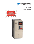
E7 Metasys® N2 Technical Manual Models: CIMR-E7U* Document Number: TM.E7.22 This page intentionally left blank This page intentionally left blank Warnings and Cautions This Section provides warnings and cautions pertinent to this product that if not heeded, may result in personal injury, fatality or equipment damage. Yaskawa is not responsible for consequences of ignoring these instructions. WARNING YASKAWA manufactures component parts that can be used in a wide variety of industrial applications. The selection and application of YASKAWA products remain the responsibility of the equipment designer or end user. YASKAWA accepts no responsibility for the way its products are incorporated into the final system design. Under no circumstances should any YASKAWA product be incorporated into any product or design as the exclusive or sole safety control. Without exception, all controls should be designed to detect faults dynamically and to fail safely under all circumstances. All products designed to incorporate a component part manufactured by YASKAWA must be supplied to the end user with appropriate warnings and instructions as to that part’s safe use and operation. Any warnings provided by YASKAWA must be promptly provided to the end user. YASKAWA offers an express warranty only as to the quality of its products in conforming to standards and specifications published in the YASKAWA manual. NO OTHER WARRANTY, EXPRESS OR IMPLIED, IS OFFERED. YASKAWA assumes no liability for any personal injury, property damage, losses, or claims arising from misapplication of its products. WARNING ! Read and understand this manual before installing, operating, or servicing this drive. All warnings, cautions, and instructions must be followed. Qualified personnel must perform all activity. The drive must be installed according to this manual and local codes. ! Do not connect or disconnect wiring while the power is on. Do not remove covers or touch circuit boards while the power is on. Do not remove or insert the digital operator while power is on. ! Before servicing, disconnect all power to the equipment. The internal capacitor remains charged even after the power supply is turned off. Status indicator LEDs and Digital Operator display will be extinguished when the DC bus voltage is below 50 VDC. To prevent electric shock, wait at least 5 minutes after all indicators are OFF and measure DC bus voltage and verify that it is at a safe level. ! Do not perform a withstand voltage test on any part of the unit. This equipment uses sensitive devices and may be damaged by high voltage. ! The drive is not suitable for circuits capable of delivering more than the specified RMS symmetrical amperes. Install adequate branch short circuit protection per applicable codes. Refer to the specification. Failure to do so may result in equipment damage and/or personal injury. ! Do not connect unapproved LC or RC interference suppression filters, capacitors, or over voltage protection devices to the output of the drive. Capacitors may generate peak currents that exceed drive specifications. ! To avoid unnecessary fault displays, caused by contactors or output switches placed between drive and motor, auxiliary contacts must be properly integrated into the control logic circuit. ! YASKAWA is not responsible for any modification of the product made by the user, doing so will void the warranty. This product must not be modified. ! Verify that the rated voltage of the drive matches the voltage of the incoming power supply before applying power. ! To meet CE directives, proper line filters and proper installation are required. ! Some drawings in this manual may be shown with protective covers or shields removed, to describe details. These must be replaced before operation. ! Observe Electrostatic Discharge Procedures when handling the drive and drive components to prevent ESD damage. ! The attached equipment may start unexpectedly upon application of power to the drive. Clear all personnel from the drive, motor and machine area prior to applying power. Secure covers, couplings, shaft keys, machine beds and all safety equipment before energizing the drive. i Introduction This manual explains the specifications and handling of the Metasys N2 protocol for the Yaskawa model E7 drive. The E7 drive with the Metasys N2 protocol selected, connects the E7 drive to a Metasys N2 network and facilitates the exchange of data. This document pertains to the Yaskawa E7 drive. Additionally, in this document, the word “inverter”, “ac drive” and “drive” may be used interchangeably. To ensure proper operation of this product, read and understand this manual. For details on installation and operation of the E7 drive or details on specific E7 parameters, refer to the E7 User Manual, document reference TM.E7.01. For details on E7 MODBUS communications, refer to the E7 MODBUS Technical Manual, document reference TM.E7.11. All technical manuals and support files are on the CD that was supplied with the drive and available for download at www.drives.com. For more information on the Metasys N2 protocol, please visit www.jci.com. GPD is a trademark of Yaskawa, Inc. MODBUS is a registered trademark of Schneider Automation, Inc. Metasys N2 is a trademark of Johnson Controls, Inc. ii Table of Contents Chapter 1 Installation........................................................................... 1-1 Installation Check Sheet.....................................................................................1-3 Metasys N2 Set-Up ............................................................................................1-5 Chapter 2 Network Connection .......................................................... 2-1 Physical Connection ...........................................................................................2-3 Chapter 3 E7 Drive Functions............................................................. 3-1 E7 Drive Functions .............................................................................................3-3 Cable Loss Configuration and Behavior .............................................................3-4 E7 Drive Fault Numbers .....................................................................................3-6 Chapter 4 Metasys N2 Point Database............................................... 4-1 Metasys N2 Analog Input (AI) Summary ............................................................4-3 Metasys N2 Analog Output (AO) Summary ........................................................4-4 Metasys N2 Binary Input (BI) Summary .............................................................4-5 Metasys N2 Binary Output (BO) Summary.........................................................4-5 Chapter 5 Mailbox Function................................................................ 5-1 Mailbox Function Points .....................................................................................5-3 Chapter 6 E7 Bypass Applications..................................................... 6-1 Bypass/Engineered Drive Parameter Settings ...................................................6-3 Appendix A Troubleshooting ................................................................. 1 Troubleshooting Check List ...................................................................................3 Installing and Configuring Metasys N2 ..................................................................5 Wiring And Cabling ................................................................................................7 Drive Faults ...........................................................................................................8 iii This page intentionally left blank. iv Chapter 1 Installation This chapter covers the initial set-up procedure for the E7 drive on a Metasys N2 network. Installation Check Sheet ................................................... 1 – 3 Metasys N2 Set-Up .............................................................1 – 5 Installation 1-1 This page intentionally left blank. Installation 1-2 Installation Check Sheet The following is a quick reference guide to the installation and configuration of the E7 drive with the Metasys N2 protocol. Make a copy of this page and check-off each item as it is completed. For detailed information please refer to the detailed sections that follow. 1: Unpack the drive and verify that all components are present and undamaged. 2: Connect power to the drive and verify that the drive functions. This includes running the drive in “Hand” mode from the digital operator without the network selected or connected. Refer to the E7 User Manual for more information on connecting and operating the drive. 3: Remove power from the drive and wait for the charge lamp to be completely extinguished. Wait at least five additional minutes after all indicators are off. Measure the DC bus voltage and verify that it is at a safe level. 4: Connect the drive to the Metasys N2 communication network. Refer to Chapter 2 – Network Connection for the Metasys N2 connection procedure. 5: If this drive is either the first or the last device on the network, set the terminating resistor switch, S1-1, to ON. If this device is not the first or last device on the network, set the terminating resistor switch, S1-1, to OFF. Refer to Chapter 2 – Network Connection for details. 6: Configure the Metasys N2 network for the drive. Refer to the documentation included with the Metasys N2 configuration software. 7: Set parameters B1-01, B1-02, H5-01, H5-02 and H5-08 to their appropriate values. Refer to Table 1.1 - Drive Communication Parameter Settings on page 1-5. Installation 1-3 This page intentionally left blank. Installation 1-4 Metasys N2 Set-Up A Yaskawa Electric America, Inc. (YEA) representative is responsible for proper configuration of the drive for its primary application, while a Johnson Controls, Inc. representative is responsible for field panel programming to make use of the drive’s functionality in the building automation system. As such, there must be coordination between the Yaskawa Electric America and Johnson Controls representatives to ensure that the programming of the drive is consistent with the particular application requirements. After verifying that the drive installation and wiring are correct, apply power to the drive. Table 1.1 below lists the parameters and their values required for proper Metasys N2 communication and control. # E7 Drive Parameter Settings for Metasys N2 Communications Parameter Number b1-01 b1-02 H5-01 H5-02 H5-08 Table 1.1 - Drive Communication Parameter Settings Digital Operator Display Settings for Metasys N2 Communication Reference Source Run Source Serial Comm Adr Serial Baud Rate Protocol Select 2: Serial Com 2: Serial Com Select the drive address (default = 1F hex (31 dec)) 3: 9600 Baud 1: N2 (Metasys) CAUTION A YEA representative should set the drive parameters to their appropriate values. Changes made to the parameters other than what is listed in the table above can result in damaging the drive or building equipment. # Programming the E7 Drive for Metasys N2 The procedure for programming the E7 drive for communication on a Metasys N2 network is shown in the table below: Table 1.2 - Drive Programming Procedure for Metasys N2 Description Key Operation Digital Operator Display -DRIVERdy Frequency Ref U1-01 = 0.00Hz ----------------U1-02 = 0.00Hz U1-03 = 0.00A Apply Power Select the Programming Menu x3 -ADV** Main Menu ** ----------------Programming -ADVInitialization ----------------A1-00 = 0 Select Language Enter the Programming Menu Installation 1-5 Table 1.2 - Drive Programming Procedure for Metasys N2 Description Key Operation Digital Operator Display x 2 Select the Reference Source for Serial Communication -ADVReference Source ----------------b1-01 = 2 *2* Serial Com “1” Select the Run Source for Serial Communication -ADVRun Source ----------------b1-02 = 2 *1* Serial Com “1” x 21 Select the N2 (Metasys N2) Communication Protocol x7 x 1 Installation 1-6 -ADVProtocol Select ---- ------------H5-08 = 1 *2* N2 (Metasys) “0” Table 1.2 - Drive Programming Procedure for Metasys N2 Description Key Operation Digital Operator Display x 7 Select the Serial Communication Address Between 0 and FE Hex (Each Device On The Metasys N2 Network Must Have A Unique Address) Change value by pressing: -ADVSerial Comm Adr ----------------H5-01 = FE (0 ~ 255) “1F” The digit to be changed blinks. Select the Serial Baud Rate of 9600 Baud Change value by pressing: -ADVSerial Baud Rate ----------------H5-02 = *3* 9600 Baud “3” The digit to be changed blinks. -DRIVE** Main Menu ** - - - - - -- - - - - - - - - Operation Select the Drive Mode -DRIVERdy Frequency Ref U1-01 = 0.00Hz ---------------U1-02 = 0.00Hz U1-03 = 0.00A Enter the Drive Mode Installation 1-7 This page intentionally left blank. Installation 1-8 Chapter 2 Network Connection This chapter discusses how to connect the E7 drive to a Metasys N2 network. Physical Connection ..........................................................2 – 3 Network Connection 2-1 This page intentionally left blank. Network Connection 2-2 Physical Connection Communication on the network is half-duplex, two wire RS-485, with communication parameters fixed at 9600 baud, eight data bits, no parity and one stop bit. The network cable is a shielded two-conductor cable. # Network Connection ! Connect a jumper between R+ and S+ and R- and S-. Figure 2.1 – E7 Terminal Block Jumper Connections ! Connect the positive (+) cable lead to S+. Connect the negative (-) cable lead to S-. Red (+) Black (-) Figure 2.2 – Metasys N2 Network Cable Connections Network Connection 2-3 Shield # Network Termination A bus-terminating resistor of 110Ω is available on each drive terminal board and can be applied to the Metasys N2 communication bus by setting switch S1-1 to the ON position. In a multi-node system, only those nodes at the end of a bus segment should have terminating resistors. Before applying a terminating resistor as described above, care should be taken to understand the physical layout of the network and where other resistors might already be applied. An overloaded or improperly terminated bus may not function properly. Figure 2.3 – Network Termination Resistor Setting Table 2.1 - Terminating Resistor Switch Setting Switch Location S1-1 Function RS-422 and RS-485 Terminating Resistance Network Connection 2-4 Setting Choices OFF: No terminating resistance ON: Terminating resistance of 110Ω Chapter 3 E7 Drive Functions This chapter discusses the E7 drive functions and cable loss behavior. E7 Drive Functions .............................................................3 – 3 Cable Loss Behavior ..........................................................3 – 4 E7 Drive Fault Numbers .....................................................3 – 6 Network Connection 3-1 This page intentionally left blank. Network Connection 3-2 E7 Drive Functions Each of the following functions must be enabled during start-up of the Drive: ! Start and stop the drive Set the RUN FORWARD COMMAND (BO 1) to run the drive in the forward direction. Set the RUN REVERSE COMMAND (BO 2) to run the drive in the reverse direction. RUN/STOP MONITOR (BI 1) shows the current run status of the drive. FORWARD/REVERSE MONITOR (BI 2) shows the current direction. CAUTION Improper drive direction may damage HVAC equipment if parameter B1-04, Reverse Enable, is improperly set (B1-04 = 0). ! Lock the E7 panel Locking the panel prevents the user from using the HAND and OFF keys locally at the drive panel. PANEL LOCK (BO 10) can be commanded to lock and unlock the panel. ! Digital Inputs MULTI-FUNCTION INPUT 1 (BO 5) through MULTI-FUNCTION INPUT 5 (BO 9) are physical digital inputs on the drive. They can be set either by external devices, such as limit or pressure switches, or by the network. Their function depends on how the drive has been programmed. Refer to the E7 User’s Manual section on Multi-Function Inputs (H1-01 through H1-05) for detailed information on the use and programming of the multi-function inputs. The multi-function input status can be monitored through MULTI-FUNCTION INPUT 1 MONITOR (BI 14) through MULTI-FUNCTION INPUT 5 MONITOR (BI 19). The MULTI-FUNCTION INPUT # MONITOR state is the logical OR of the serial command value (BO 5 through BO 9) and the state of the external connection. CAUTION Because the multi-function inputs can be set by both external devices or over the network, care must be taken when connecting the multi-function inputs to external devices to ensure correct system operation. ! Digital Outputs MULTI-FUNCTION OUPUT 1 (BI 10) through MULTI-FUNCTION OUPUT 3 (BI 12) are physical digital outputs on the drive. Their function depends on how the drive has been programmed. Refer to the E7 User’s Manual section on Multi-Function Outputs (H2-01 through H2-03) for detailed information on the use and programming of the multi-function outputs. ! Loop gain PI PROPORTIONAL GAIN (AO 4) and PI INTEGRAL TIME (AO 5) are the gain and integral time parameters used by the E7. The E7 PI loop is structured differently than the Metasys loop. Refer to the E7 User’s Manual section on PID for information on how the E7 PI loop functions. ! Reading and resetting faults FAULT MONITOR (BI 4) and DRIVE READY MONITOR (BI 3) show the current status of the drive. FAULT CODE (AI 10) contains the code for the most current fault. LST FLT CODE (AI 19) contains the code for the previous fault. See table below for descriptions of the fault codes. The drive fault can be reset through FAULT RESET COMMAND (BO 4). The FAULT RESET COMMAND is only available when the RUN FORWARD COMMAND and the RUN REVERSE COMMAND are both OFF. Network Connection 3-3 Cable Loss Configuration and Behavior This section describes the configurable cable loss feature of the drive. This feature offers a user maximum flexibility in determining the drive’s response to a loss of communication. # Drive Behavior At Loss of Communication ! After some interval without receipt of a message, the drive can be configured to respond in one of the following manners: $ Continue at last speed $ Continue at last speed with Alarm $ Continue at preset speed $ Ramp to Stop with EF0 fault $ Coast to Stop with EF0 fault $ Emergency Stop with EF0 fault # Metasys N2 I/O Three Metasys N2 outputs are used to select the desired behavior: ! AO 21 – Cable Loss Timeout ! AO 22 – Cable Loss Speed ! BO 11 – Communication Fault Enable Table 5.1 - Cable Loss Behavior Summary Behavior H5-04 Cable Loss Timeout Cable Loss Speed Communication Fault Enable (AO 121 (AO 22) (BO 11) Decelerate to stop (stop time in C1-02) EF0 Fault 0 Timeout Interval X On Coast to stop EF0 Fault 1 Timeout Interval X On Emergency stop (stop time in C1-09) EF0 Fault 2 Timeout Interval X On Continue at last speed 3 0 X X Continue at last speed with Alarm 3 Timeout Interval X On Continue at preset speed with Alarm 4 Timeout Interval Preset Speed On Notes: 1. Communication must first be established and then lost for these features to function as described. If a drive is powered-up without a cable connected or with the master controller offline, a communications timeout does not occur. 2. For modes which describe the drive running after a communications timeout, a run command must have been issued (BO 1 = ‘On’ or BO 2 = ‘On’) prior to loss of communications. For safety purposes, the drive will not automatically restart from a stopped condition. If a user requires the drive to restart automatically, additional external wiring is required to accomplish this (consult factory). Upon expiration of the communications timeout interval, the FAULT LED lights and remains lit until communication is restored. ! Continue at Last Speed In this mode, Cable Loss Timeout (AO 21) is set to 0, disabling the cable loss feature. The other two settings Cable Loss Speed (AO 22) and Communication Fault Enable (BO 11) are ignored. If communication is lost, the drive simply maintains its last commanded state. The drive will not display an alarm or fault to indicate it has lost communication. This behavior can also be achieved by setting parameter H5-04 to “3”. The drive will display an alarm and continue running. For this specific condition, the Communication Fault Enable (BO 11) must be enabled and Cable Loss Timeout (AO 21) should be set to something other than 0. ! Continue at Preset Speed In this mode, Cable Loss Timeout (AO 21) is set to the desired interval, Cable Loss Speed (AO 22) is set to the desired preset speed and H5-04 is set to “4”. If the time between messages exceeds the timeout interval, the drive’s speed command (AO 1) is set to the Cable Loss Speed (AO 22) and the drive continues running at this new speed. Communication Fault Enable (BO 11) must be set to ‘On’. Network Connection 3-4 ! Stop Communication Fault Enable (BO 11) must be set to ‘On’. In this mode, Cable Loss Timeout (AO 21) is set to the desired interval and parameter H5-04 is set to a value of 0,1 or 2. If the time between messages exceeds the timeout interval, the drive’s speed command (AO 1) is set to 0. The stopping method is determined by the setting of H5-04. An EF0 drive fault will be set. $ H5-04 = 0 selects Ramp to Stop. The deceleration time or the slope of the ramp is determined by the setting of drive parameter C1-02. $ H5-04 = 1 selects Coast to Stop. The drive does not attempt to control the rate of deceleration. $ H5-04 = 2 selects Emergency or Fast Stop. The deceleration time is determined by the setting of drive parameter C1-09. CAUTION The behavior of the drive at cable loss is controlled by parameter H5-04. This drive parameter works with the points as described in the table above to determine how the drive will respond to a cable loss. If the cable loss fault is disabled, the drive will continue in its last state, if running the drive will continue to run at the last commanded frequency. ! Fault (EF0) In this mode, Cable Loss Timeout (AO 21) is set to the desired interval and Communication Fault Enable (BO 11) is set to ‘On’. If the time between messages exceeds the timeout interval, an ‘EF0’ fault is declared and the drive stops. The stopping method is controlled by the setting of H5-04 and is described above. Cable Loss Speed (AO 22) is ignored. Network Connection 3-5 E7 Drive Fault Numbers Fault Number 1 2 3 4 6 7 8 9 10 11 12 13 14 17 18 19 20 21 28 31 33 39 Table 3.1 - Description of Fault Numbers Description DC Bus Fuse Open (PUF) DC Bus Undervolt (UV1) Control Power Supply Undervolt (UV2) MC Answerback (UV3) Ground Fault (GF) Overcurrent (OC) DC Bus Overvolt (OV) Overheat (OH) Overheat 1 (OH1) Motor Overload (OL1) Inverter Overload (OL2) Overtorque Detection 1 (OL3) Overtorque Detection 2 (OL4) External Fault 3 (EF3) External Fault 4 (EF4) External Fault 5 (EF5) External Fault 6 (EF6) External Fault 7 (EF7) Output Phase Loss (LF) Operator Connection Fault (OPR) Memobus Com Error (CE) External Fault 0 (EF0) Network Connection 3-6 Chapter 4 Metasys N2 Point Database This chapter shows the Metasys N2 point database. This database features 100 logical points: 38 Analog Inputs (AI), 32 Analog Outputs (AO), 19 Binary Inputs (BI) and 11 Binary Outputs (BO). These points configure, control or monitor the operation of the drive. Metasys N2 Analog Input (AI) Summary...........................4 – 3 Metasys N2 Analog Output (AO) Summary ......................4 – 4 Metasys N2 Binary Input (BI) Summary............................4 – 5 Metasys N2 Binary Output (BO) Summary.......................4 – 5 Cable Loss Behavior 4-1 This page intentionally left blank. Cable Loss Behavior 4-2 Metasys N2 Analog Input (AI) Summary Object ID Table 4.1 – Metasys N2 Analog Input Summary (E7 to Metasys N2) Object Name Units E7 Parameter AI 1 SPEED REFERENCE 0.01 Hz U1-01 AI 2 OUTPUT SPEED 0.01 Hz U1-02 AI 3 OUTPUT CURRENT 0.1 A U1-03 AI 4 kWATT HOUR METER kWh - AI 5 OUTPUT POWER 0.1 kW U1-08 AI 6 DRIVE TEMPERATURE 1 oC - AI 7 PI FEEDBACK 0.01% U1-24 AI 8 AC OUTPUT VOLTAGE 0.1Vac U1-06 AI 9 DC BUS VOLTAGE 1Vdc U1-07 AI 10 FAULT CODE - U2-01 AI 11 ELAPSED TIME - HOURS 1 HOUR U1-13 AI 12 ELAPSED TIME – 10K HOURS 10K HOURS U1-13 AI 13 MEGAWATT HOUR METER MWh U1-30 AI 14 DRIVE RATED CURRENT A n9-01 AI 15 COMMUNICATION ERROR CODE - U1-39 AI 16 PI DEVIATION 0.01% U1-36 AI 17 PI OUTPUT CAPACITY 0.01% U1-37 AI 18 PI REFERENCE 0.01% U1-38 AI 19 LAST FAULT CODE - U2-02 AI 20 FREQ REF @ FAULT 0.01Hz U2-03 AI 21 OUTPUT FREQ @ FAULT 0.01Hz U2-04 AI 22 OUTPUT CURRENT @ FAULT 0.1A U2-05 AI 23 OUT VOLT REF @ FAULT 0.1Vac U2-07 AI 24 DC BUS VOLTS @ FAULT 1Vdc U2-08 AI 25 OUTPUT POWER @ FAULT 0.1Kw U2-09 AI 26 INPUT TERM STATUS @ FAULT - U2-11 AI 27 OUTPUT TERM STATUS @ FAULT - U2-12 AI 28 OPERATION STATUS @ FAULT - U2-13 AI 29 ELAPSED OPERATION TIME @ FAULT 1 HOUR U2-14 AI 30 MOST RECENT FAULT - U3-01 AI 31 2nd MOST RECENT FAULT - U3-02 AI 32 3rd MOST RECENT FAULT - U3-03 AI 33 4th MOST RECENT FAULT - U3-04 AI 34 ELAPSED TIME @ CURRENT FAULT 1 HOUR U3-05 AI 35 ELAPSED TIME @ 2nd FAULT 1 HOUR U3-06 AI 36 ELAPSED TIME @ 3rd FAULT 1 HOUR U3-07 AI 37 ELAPSED TIME @ 4th FAULT 1 HOUR U3-08 AI 38 READ PARAMETER DATA - - Cable Loss Behavior 4-3 Metasys N2 Analog Output (AO) Summary Object ID Table 4.2 – Metasys N2 Analog Output Summary (Metasys N2 to E7) Object Name Units Default Value E7 Parameter AO 1 SPEED COMMAND 0.01 Hz AO 2 ACCELERATION TIME SEC 30.0 C1-01 - AO 3 DECELERATION TIME SEC 30.0 C1-02 AO 4 PI PROPORTIONAL GAIN - 2.00 b5-02 AO 5 PI INTEGRAL TIME SEC 5.0 b5-03 AO 6 STALL PREVENTION LEVEL – RUN % 120 L3-06 AO 7 STALL PREVENTION LEVEL – ACCEL % 120 L3-02 AO 8 REFERENCE OPERATION MODE SELECT - 1 b1-01 AO 9 RUN OPERATION MODE SELECT - 1 b1-02 AO 10 PI MODE SELECT - 0 b5-01 AO 11 FREQUENCY COMMAND UPPER LIMIT % of MAX 100.0 d2-01 AO 12 FREQUENCY COMMAND LOWER LIMIT % of MAX 0.0 d2-02 AO 13 MOTOR RATED CURRENT A Motor model dependent E2-01 AO 14 JUMP FREQUENCY 1 0.1Hz 0.0 d3-01 AO 15 JUMP FREQUENCY 2 0.1Hz 0.0 d3-02 AO 16 JUMP FREQUENCY 3 0.1Hz 0.0 d3-03 AO 17 JUMP FREQUENCY BANDWIDTH 0.1Hz 1.0 d3-04 AO 18 NUMBER OF AUTO RESTARTS - 0 L5-01 AO 19 OPERATOR DISPLAY MODE - 0 o1-03 AO 20 POWER LOSS RIDE THROUGH SEC Drive model dependent L2-02 AO 21 CABLE LOSS TIME-OUT SEC 2.0 H5-09 AO 22 CABLE LOSS SPEED 0.01Hz 0.00 d1-04 AO 23 PI INTEGRAL LIMIT 0.1% 100.0 b5-04 AO 24 PI UPPER LIMIT VALUE 0.1 100.0 b5-06 AO 25 PI OFFSET ADJUSTMENT 0.1 0.0 b5-07 AO 26 PI PRIMARY DELAY TIME 0.01 0.00 b5-08 AO 27 PI FEEDBACK REFERENCE MISSING DETECTION SELECT 1 0 b5-12 AO 28 PI FEEDBACK REFERENCE MISSING DETECTION LEVEL 1% 0 b5-13 AO 29 PI FEEDBACK REFERENCE MISSING DETECTION TIME 0.1 SEC 1.0 b5-14 AO 30 READ PARAMETER NUMBER - - AO 31 WRITE PARAMETER NUMBER - - AO 32 WRITE PARAMETER DATA - - Cable Loss Behavior 4-4 Metasys N2 Binary Input (BI) Summary Object ID BI 1 BI 2 BI 3 BI 4 BI 5 BI 6 BI 7 BI 8 BI 9 BI 10 BI 11 BI 12 Table 4.3 – Metasys N2 Binary Input Summary (E7 to Metasys N2) Object Name Default Off (0) State RUN / STOP MONITOR FORWARD / REVERSE MONITOR DRIVE READY MONITOR FAULT MONITOR ZERO SPEED SPEED AGREE MINOR FAULT MAJOR FAULT DRIVE COMMUNICATION ERROR MONITOR MULTI-FUNCTION OUTPUT 1 (H2-01) MULTI-FUNCTION OUTPUT 2 (H2-02) MULTI-FUNCTION OUTPUT 3 (H2-03) On (1) State 0 0 0 0 0 0 0 0 STOPPED FORWARD NOT READY NOT FAULTED NOT ZERO SPEED NOT SPEED AGREE NO MINOR FAULT NO MAJOR FAULT RUNNING REVERSE READY FAULTED ZERO SPEED SPEED AGREE MINOR FAULT MAJOR FAULT 0 NO ERROR ERROR 0 SAFETY CLEAR TERMINAL 3 CLOSED REMOTE OFF OFF OFF OFF OFF SAFETY SET TERMINAL 3 OPEN LOCAL ON ON ON ON ON 0 0 BI 13 SAFETY INTERLOCK MONITOR 0 BI 14 BI 15 BI 16 BI 17 BI 18 BI 19 HAND / AUTO REFERENCE MONITOR MULTI-FUNCTION INPUT 1 MONITOR MULTI-FUNCTION INPUT 2 MONITOR MULTI-FUNCTION INPUT 3 MONITOR MULTI-FUNCTION INPUT 4 MONITOR MULTI-FUNCTION INPUT 5 MONITOR 0 0 0 0 0 0 Metasys N2 Binary Output (BO) Summary Object ID Table 4.4 – Metasys N2 Binary Output Summary (Metasys N2 to E7) Object Name Default Off (0) State BO 1 BO 2 BO 3 BO 4 BO 5 BO 6 BO 7 BO 8 BO 9 RUN FORWARD COMMAND RUN REVERSE COMMAND SERIAL FAULT (EF0) COMMAND FAULT RESET COMMAND MULTI-FUNCTION INPUT 1 (H1-01) MULTI-FUNCTION INPUT 2 (H1-02) MULTI-FUNCTION INPUT 3 (H1-03) MULTI-FUNCTION INPUT 4 (H1-04) MULTI-FUNCTION INPUT 5 (H1-05) 0 0 0 0 0 0 0 0 0 BO 10 PANEL LOCK 0 BO 11 COMMUNICATION FAULT ENABLE 0 STOP STOP NO FAULT NO RESET LOCAL/REMOTE AND STOP/RESET KEYS ENABLED EF0 NOT ACTIVATED IF CABLE LOSS OCCURS Cable Loss Behavior 4-5 On (1) State FORWARD REVERSE FAULT RESET - LOCAL/REMOTE AND STOP/RESET KEYS DISABLED EF0 ACTIVATED IF CABLE LOSS OCCURS This page intentionally left blank. Cable Loss Behavior 4-6 Chapter 5 Mailbox Function This chapter defines the Metasys N2 points that read and write E7 drive parameters. Mailbox Function Points ................................................... 5 – 3 Mailbox Function 5-1 This page intentionally left blank. Mailbox Function 5-2 Mailbox Function Points # Reading a Drive Parameter Two points are defined for reading any drive parameter: ! AO 30 Specifies the parameter to be read from the E7 drive ! AI 38 Reports the value of the parameter specified in AO 30 When this point is read, it retrieves data from the parameter and sends it to the controller ! Example: Writing a value of 387 (183 hex) to AO 30 specifies drive parameter b1-04. Reading AI 38 returns the current setting of parameter b1-04 to the controller # Writing to a Drive Parameter Two points are defined for writing to any drive parameter: ! AO 31 ! AO 32 Entry location of the value to be written to the parameter specified in AO 31. When this point is written to, it will write the value to the drive. An ENTER or ACCEPT command does not need to be sent for the data to be taken by the drive. The behavior of the write is the same as with the digital operator. If the drive is running, there are a limited number of drive parameters that can be written to. ! Example: Specifies the parameter to be written to Writing a value of 387 (183 hex) to AO 31 specifies drive parameter b1-04. Writing a value of 1 to AO 32 enables the drive for reverse run. Mailbox Function 5-3 This page intentionally left blank. Mailbox Function 5-4 Chapter 6 E7 Bypass Applications This chapter lists the typical parameters for a bypass/engineered drive. Bypass/Engineered Drive Parameter Settings................ 6 – 3 E7 Bypass Applications 6-1 This page intentionally left blank. E7 Bypass Applications 6-2 Bypass/Engineered Drive Parameter Settings For many applications, the drive is integrated into a bypass or engineered package. This type of package typically features an enclosure with contactors that allow the user to run the motor from line power (bypass mode) or from the drive (drive mode). This package also provides the flexibility for interfacing normally closed safety interlocks (fire status, freeze status, vibration sensors, etc.) which stop the drive if the contacts open. # Typical Parameter Settings A bypass/engineered drive is supplied with a list of parameters and their default values. Use the table below to record any parameter modifications for this particular application. Table 7.1 - Typical Bypass/Engineered Drive Parameters Parameter Number Bypass Settings Default Description User E1-01 Input Voltage (VAC) – (default dependent on drive model) E1-05 Maximum Output voltage (VAC) – (default dependent on drive mode)l E2-01 Motor Rated Current (FLA) (A) – (default dependent on drive model) T1-02 Motor Rated Power (kW) – (default dependent on motor) T1-04 Motor Rated Current (FLA) (A) – (default dependent on motor) A1-01 2 Parameter Access Level (2 – Advanced) B1-01 Frequency Reference Source (dependent on bypass options specified) B1-02 Command Source (dependent on bypass options specified) B1-03 0 Stopping Method (0 – Ramp to Stop) (ramp slope set by C1-02) B1-04 1 Reverse Operation (1 – Disabled) B1-07 1 Local/Remote RUN Selection (1 – Accept External RUN) B1-08 1 RUN Command During Programming (1 – Enabled) B1-12 HAND Mode Frequency Reference Selection (Operator Keypad) B2-02 50% B2-03 5.0 sec DC Injection Braking Current @ Start (5.0sec) B2-09 0.0 A Motor Preheat Current B3-01 1 Speed Search Select (1 – Enabled (Speed Estimated)) B8-01 1 Energy Conservation Control Select (1 – Enabled) C1-01 60.0 sec Acceleration Time C1-02 60.0 sec Deceleration Time D1-01 10.0 hz Frequency Reference 1 (HAND Mode) (see H1-03) D1-02 20.0 hz Frequency Reference 2 (HAND Mode) (see H1-03) E1-01 E1-03 DC Injection Braking Current (50%) Input Voltage– (default dependent on drive model) 7 E1-05 V/F Pattern Select Output Voltage– Parameter defaults dependent on drive model F6-01 3 Operation After Communication Loss (3 – Alarm Only) H1-01 70 hex Terminal S3 Function (Bypass Drv Enbl) H1-02 6 hex Terminal S4 Function (Local /Remote Select) H1-03 6C hex Terminal S5 Function (Frequency Reference 2 (N.O.)) H1-04 20 hex Terminal S6 Function (External Fault (N.O.)) E7 Bypass Applications 6-3 Table 7.1 - Typical Bypass/Engineered Drive Parameters Bypass Settings Parameter Number Default H1-05 8 hex H2-02 3B hex H3-08 2 Terminal A2 (0–10vdc) H3-09 2 Terminal A2 (Auxiliary Frequency Reference) H3-12 0.3 sec H3-13 0 Master Frequency Reference Terminal Select (0 – Terminal A1) L2-01 2 Momentary Power Loss Detection Select (2 – CPU power active) (UV fault not detected) L4-05 1 Frequency Reference Loss Detection Select (1 – RUN @ 80% of frequency prior to loss) L5-01 10 Number of Re-Start Attempts L5-03 600.0 sec L6-01 6 L6-02 15% L6-03 10.0 sec L8-03 4 L8-11 300 sec L8-19 20% O2-01 0 Local/Remote Key Function (0 - Disabled) O2-02 0 OFF Key Function (0 – Disabled) O2-05 1 Frequency Reference Setting Method select (1 – Enabled) (Enter key Not Required from Keypad) O2-08 1 Cumulative Operation Time Select (1 – Time @ RUN) O3-02 1 Keypad COPY Function Select (1 – Enabled) Description User Terminal S7 Function (External Base Block (N.O.)) Terminal M3-M4 (Command Source – Serial) Analog Input Filter Time Maximum Restart Time After Fault Torque Detection Select (6 – No Load Detect and Alarm) Torque Detection Level (% of drive rated current) Torque Detection Time Overheat Pre-Alarm Operation Select (4 – Alarm and Reduce) Heatsink cooling Fan Operation Delay Time Overheat Frequency Reference Reduction Level E7 Bypass Applications 6-4 Appendix A Troubleshooting This appendix describes the steps necessary to troubleshoot the E7 drive communicating on a Metasys N2 network. Troubleshooting Check List .............................................. A - 3 Installing and Configuring Metasys N2............................ A – 5 Wiring And Cabling ........................................................... A – 7 Drive Faults ........................................................................ A – 8 Troubleshooting A-1 This page intentionally left blank. Troubleshooting A-2 Troubleshooting Check List 1: 2: Connect power to the drive and verify that the drive operates correctly in HAND mode from the digital operator without being connected to the network. Record the drive model number and “spec” number at this time: Model Number: CIMR-E7U ___ ___ ___ ___ (e.g. CIMR-E7U20P4) ”SPEC” Number: ___ ___ ___ ___ ___ ___ (e.g. 20P41A) Record the control board part number: ETC - ___ ___ ___ ___ ___ ___ - ___ ___ ___ ___ ___ 3: All network devices have unique addresses and drives are addressed between 0-255 (0-FE hex). Drive address: 4: (e.g. ETC-618021-S2012) ____________ The Run/Stop command source parameter, b1-02 is set correctly. b1-02: ____________ 5: The Speed Command source parameter, b1-01, is set correctly. b1-01: ____________ 6: The correct cable type is used: Mfg: ____________________ P/N: ____________________ 7: All cable connections are correct per device schematic and are secure. 8: All cables have been checked for continuity. There are no breaks or shorts. 9: The network is correctly terminated. 10: The shield is continuous throughout the network and is properly grounded on each end. 11: The network cable is routed away from any high voltage cable(s) or source(s). 12: All network devices have been tested for conformance with the Metasys N2 specification. Troubleshooting A-3 This page intentionally left blank. Troubleshooting A-4 Installing and Configuring Metasys N2 The following is a short guide to troubleshooting the Metasys N2 installation and configuration. It highlights some of the most common issues faced when diagnosing and correcting issues associated with the startup and operation of an E7 drive with Metasys N2 building automation network. While most of the information is centered on the application of the drive, the guidelines presented are applicable in most Metasys N2 networks. Diagnosis of network fault issues will typically fall into three categories: 1: Installation/set-up of Metasys N2, 2: wiring and cabling issues, and 3: network configuration/diagnostics. Each of these areas will be discussed after to help resolve common problems associated in Metasys N2 network troubleshooting. # Drive Operates Correctly Without Network Enabled Before programming the drive for Metasys N2 communication, verify that the drive functions properly. Refer to the E7 User Manual (TM.E7.01) for information on the drive’s installation and operation. # Network Cable Is Connected Correctly And Securely ! Connect a jumper between R+ and S+ as well as R- and S-. Connect network cable to terminals S+ and S+. Black (-) Red (+) Shield Figure A.1 – E7 Metasys N2 Network Connections # Run/Stop Operation Parameter Is Set Correctly The run/stop operation parameter needs to be set for “Serial Com”. Table A.1 - Run/Stop Operation Parameter Parameter Number Setting Choices 0 b1-02 Setting Descriptions Operator 1 Terminals 2 Serial Com (Metasys N2) 3 Option PCB Troubleshooting A-5 # Speed Command Operation Parameter Is Set Correctly The speed command operation parameter needs to be set for “Serial Com”. Table A.2 - Speed Command Operation Parameter Parameter Number Setting Choices 0 b1-01 Setting Descriptions Operator 1 Terminals 2 Serial Com (Metasys N2) 3 Option PCB # Correct and Unique Network Address Each device on a Metasys N2 network requires its own unique address. The drive also needs to be programmed to accept the Metasys N2 protocol. Table A.3 - Serial Communication Device Address Parameter Parameter Number Setting Range H5-01 0 to 20 hex H5-08 0 to 2 Troubleshooting A-6 Setting Description Serial communication device address 1: N2 (Metasys) Wiring And Cabling # The network cable is the correct type Table A.4 - Metasys N2 Cable Specifications Specification Cable Configuration Description Twisted Shielded Pair Gauge 18-20 AWG (Solid or Stranded) Wire Lay Minimum 6 twists per foot Shields 100% foil with drain wire NEC Type UL Type CMP Temperature 60oC or higher # Cable Lengths Are Within Specified Limits Cable lengths cannot exceed 500 feet at 9600 baud. # The Network is Terminated Correctly A bus terminating resistor of 110Ω is available on each drive terminal board and can be applied to the Metasys N2 communication bus by setting switch S1-1 to the ON position. In a multi-node system, only those nodes at the end of a bus segment should have terminating resistors. Before applying a terminating resistor as described above, care should be taken to understand the physical layout of the network and where other resistors might already be applied. An overloaded or improperly terminated bus may not function properly. Figure A.2 – Termination Resistor Setting Table A.5 - Terminating Resistor Switch Setting Switch Location S1-1 Function RS-422 and RS-485 Terminating Resistance Setting Choices OFF: No terminating resistance ON: Terminating resistance of 110Ω # Shield Is Continuous And Both Ends Of The Shield Are Grounded As each drive is daisy-chained to the next, twist together the shields of the adjoining cables. Do not connect the shield at each drive. The continuous shield should then be single-point grounded at the field panel. # Cable Is Routed Correctly Route the cable away from all power and high frequency lines. Routing within a separate conduit is preferred. Troubleshooting A-7 Drive Faults # Communications Fault Table A.6 - Drive Faults Fault CE Description Memobus Communication Error Cause Connection is broken or master has stopped communicating Corrective Action Check all connections Verify all Metasys N2 software configurations # E7 Drive Faults Fault Number 1 2 3 4 6 7 8 9 10 11 12 13 14 17 18 19 20 21 28 31 33 39 Table A.7 – E7 Drive Faults Description DC Bus Fuse Open (PUF) DC Bus Undervolt (UV1) Control Power Supply Undervolt (UV2) MC Answerback (UV3) Ground Fault (GF) Overcurrent (OC) DC Bus Overvolt (OV) Overheat (OH) Overheat 1 (OH1) Motor Overload (OL1) Inverter Overload (OL2) Overtorque Detection 1 (OL3) Overtorque Detection 2 (OL4) External Fault 3 (EF3) External Fault 4 (EF4) External Fault 5 (EF5) External Fault 6 (EF6) External Fault 7 (EF7) Output Phase Loss (LF) Operator Connection Fault (OPR) Memobus Com Error (CE) External Fault 0 (EF0) Troubleshooting A-8 E7 Metasys® N2 YASKAWA ELECTRIC AMERICA, INC. Drives Division 16555 W. Ryerson Rd., New Berlin, WI 53151, U.S.A. Phone: (800) YASKAWA (800-927-5292) Fax: (262) 782-3418 Internet: http://www.drives.com YASKAWA ELECTRIC AMERICA, INC. Chicago-Corporate Headquarters 2121 Norman Drive South, Waukegan, IL 60085, U.S.A. Phone: (800) YASKAWA (800-927-5292) Fax: (847) 887-7310 Internet: http://www.yaskawa.com MOTOMAN INC. 805 Liberty Lane, West Carrollton, OH 45449, U.S.A. Phone: (937) 847-6200 Fax: (937) 847-6277 Internet: http://www.motoman.com YASKAWA ELECTRIC CORPORATION New Pier Takeshiba South Tower, 1-16-1, Kaigan, Minatoku, Tokyo, 105-0022, Japan Phone: 81-3-5402-4511 Fax: 81-3-5402-4580 Internet: http://www.yaskawa.co.jp YASKAWA ELETRICO DO BRASIL COMERCIO LTDA. Avenida Fagundes Filho, 620 Bairro Saude Sao Paolo-SP, Brasil CEP: 04304-000 Phone: 55-11-5071-2552 Fax: 55-11-5581-8795 Internet: http://www.yaskawa.com.br YASKAWA ELECTRIC EUROPE GmbH Am Kronberger Hang 2, 65824 Schwalbach, Germany Phone: 49-6196-569-300 Fax: 49-6196-888-301 MOTOMAN ROBOTICS AB Box 504 S38525, Torsas, Sweden Phone: 46-486-48800 Fax: 46-486-41410 MOTOMAN ROBOTEC GmbH Kammerfeldstrabe 1, 85391 Allershausen, Germany Phone: 49-8166-900 Fax: 49-8166-9039 YASKAWA ELECTRIC UK LTD. 1 Hunt Hill Orchardton Woods Cumbernauld, G68 9LF, Scotland, United Kingdom Phone: 44-12-3673-5000 Fax: 44-12-3645-8182 YASKAWA ELECTRIC KOREA CORPORATION Paik Nam Bldg. 901 188-3, 1-Ga Euljiro, Joong-Gu, Seoul, Korea Phone: 82-2-776-7844 Fax: 82-2-753-2639 YASKAWA ELECTRIC (SINGAPORE) PTE. LTD. Head Office: 151 Lorong Chuan, #04-01, New Tech Park Singapore 556741, Singapore Phone: 65-282-3003 Fax: 65-289-3003 TAIPEI OFFICE (AND YATEC ENGINEERING CORPORATION) 10F 146 Sung Chiang Road, Taipei, Taiwan Phone: 886-2-2563-0010 Fax: 886-2-2567-4677 YASKAWA JASON (HK) COMPANY LIMITED Rm. 2909-10, Hong Kong Plaza, 186-191 Connaught Road West, Hong Kong Phone: 852-2803-2385 Fax: 852-2547-5773 BEIJING OFFICE Room No. 301 Office Building of Beijing International Club, 21 Jianguomanwai Avenue, Beijing 100020, China Phone: 86-10-6532-1850 Fax: 86-10-6532-1851 SHANGHAI OFFICE 27 Hui He Road Shanghai 200437 China Phone: 86-21-6553-6600 Fax: 86-21-6531-4242 SHANGHAI YASKAWA-TONJI M & E CO., LTD. 27 Hui He Road Shanghai 200437 China Phone: 86-21-6533-2828 Fax: 86-21-6553-6677 BEIJING YASKAWA BEIKE AUTOMATION ENGINEERING CO., LTD. 30 Xue Yuan Road, Haidian, Beijing 100083 China Phone: 86-10-6232-9943 Fax: 86-10-6234-5002 SHOUGANG MOTOMAN ROBOT CO., LTD. 7, Yongchang-North Street, Beijing Economic & Technological Development Area, Beijing 100076 China Phone: 86-10-6788-0551 Fax: 86-10-6788-2878 YEA, TAICHUNG OFFICE IN TAIWAIN B1, 6F, No.51, Section 2, Kung-Yi Road, Taichung City, Taiwan, R.O.C. Phone: 886-4-2320-2227 Fax:886-4-2320-2239 YEA Document Number: TM.E7.22 8/1/2002 Data subject to change without notice. Yaskawa Electric America, Inc. Version: 3010