1
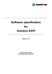
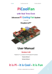
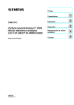
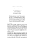
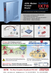
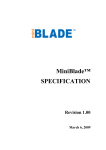
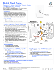
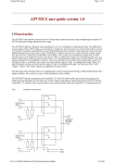
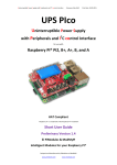
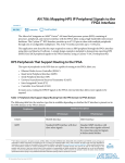
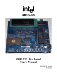
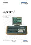
Industry Standard Control Interfaces for inter IC
Communication
Moritz Nöltner
Institut für Technische Informatik
Lehrstuhl für Rechnerarchitektur
Universität Heidelberg
January 28, 2015
Introduction SPI I2 C Measurements Conclusion
Table of Contents
1
Introduction
2
Serial Peripheral Interface
3
Inter-Integrated Circuit
4
Practical Part
5
Conclusion
Moritz Nöltner
2 / 35
Introduction SPI I2 C Measurements Conclusion
Table of Contents
1
Introduction
2
Serial Peripheral Interface
3
Inter-Integrated Circuit
4
Practical Part
5
Conclusion
Moritz Nöltner
3 / 35
Introduction SPI I2 C Measurements Conclusion
How to Connect Circuits?
Device 1
??
Device 2
HyperTransport
CAN
PATA, SATA
UART, USART
PCI, PCI-Express
SPI
AGP
I2 C, SMBus
ISA
UNI/O
USB
1-Wire
Moritz Nöltner
4 / 35
Introduction SPI I2 C Measurements Conclusion
Speed <=> Simplicity
Source: http://www.anandtech.com/show/2354/2
Moritz Nöltner
5 / 35
Introduction SPI I2 C Measurements Conclusion
Table of Contents
1
Introduction
2
Serial Peripheral Interface
3
Inter-Integrated Circuit
4
Practical Part
5
Conclusion
Moritz Nöltner
6 / 35
Introduction SPI I2 C Measurements Conclusion
Serial Peripheral Interface
Created in the 1980s
First used in Motorola
6800
Very widely accepted
Bus system
Full duplex
Source: http://en.wikipedia.org/wiki/File:
Motorola_MC6800_microprocessor.jpg
Moritz Nöltner
Four signal lines
typically
7 / 35
Introduction SPI I2 C Measurements Conclusion
SPI Signal Lines
Source: Adapted from ``SPI Block Guide V 03.06'', 2003
Moritz Nöltner
8 / 35
Introduction SPI I2 C Measurements Conclusion
SPI Signal Lines
Source: Adapted from ``SPI Block Guide V 03.06'', 2003
• SS
Slave Select
Slaves will only interact if their SS is acrive
Moritz Nöltner
8 / 35
Introduction SPI I2 C Measurements Conclusion
SPI Signal Lines
Source: Adapted from ``SPI Block Guide V 03.06'', 2003
• MOSI
Master Out, Slave In
Serial data line for master to slave
Moritz Nöltner
8 / 35
Introduction SPI I2 C Measurements Conclusion
SPI Signal Lines
Source: Adapted from ``SPI Block Guide V 03.06'', 2003
• MISO
Master In, Slave Out
Serial data line for master to slave
Moritz Nöltner
8 / 35
Introduction SPI I2 C Measurements Conclusion
SPI Signal Lines
Source: Adapted from ``SPI Block Guide V 03.06'', 2003
• CLOCK
Shift Clock
One bit is sent per clock cycle
Moritz Nöltner
8 / 35
Introduction SPI I2 C Measurements Conclusion
Clock Phase & Polarity
4 combinations:
Source: Taken from the datasheet for Motorola MC68HC11A0
Moritz Nöltner
9 / 35
Introduction SPI I2 C Measurements Conclusion
SPI Bus Topologies: Star
3+n signal lines
MOSI, MISO, CLOCK shared
One SS for every slave
Master activates a slave and
communicates with it
No delay
Source: Adapted from
http://en.wikipedia.org/wiki/File:
SPI_three_slaves.svg
Moritz Nöltner
10 / 35
Introduction SPI I2 C Measurements Conclusion
SPI Bus Topologies: Serial
Four signal lines
MOSI, MISO, CLOCK, SS
shared
Messages are passed through
Messages get latched, when
SS is deasserted
Not supported by all devices
Source: Adapted from
http://en.wikipedia.org/wiki/File:
SPI_three_slaves_daisy_chained.svg
Moritz Nöltner
Delayed responses, message
has to pass adjacent slaves
11 / 35
Introduction SPI I2 C Measurements Conclusion
Table of Contents
1
Introduction
2
Serial Peripheral Interface
3
Inter-Integrated Circuit
4
Practical Part
5
Conclusion
Moritz Nöltner
12 / 35
Introduction SPI I2 C Measurements Conclusion
Inter-Integrated Circuit
Created in the 1980s
First used in Philips
MAB8400B
Very widely accepted
Compatible with
other buses: SMBus,
PMBus
Bus system
Source:
http://www.cpushack.com/gallery-1/philips/philipsmab8400b
Multi-master
operation
Half duplex (simplex)
Two signal lines +
two pull-up resistors
Moritz Nöltner
13 / 35
2
Introduction SPI I2 C Measurements Conclusion
I C Roles
Four roles possible:
•Master
•Slave
•Transmitter
•Receiver
Starts a transmission
Responds to transmission
Transmits data
Receives data
Moritz Nöltner
14 / 35
2
Introduction SPI I2 C Measurements Conclusion
I C Signal Lines
Source: Adapted from ``The I2 C-Bus Specification v. 2.1'', 2000
Moritz Nöltner
15 / 35
2
Introduction SPI I2 C Measurements Conclusion
I C Signal Lines
Source: Adapted from ``The I2 C-Bus Specification v. 2.1'', 2000
•SDA
Seria Data
Bidirectional data– & address line
Moritz Nöltner
15 / 35
2
Introduction SPI I2 C Measurements Conclusion
I C Signal Lines
Source: Adapted from ``The I2 C-Bus Specification v. 2.1'', 2000
•SCL
Serial Clock
Used by the master to synchronise with the
slaves
Moritz Nöltner
15 / 35
2
Introduction SPI I2 C Measurements Conclusion
I C Electrical Setup
Open-drain or
open-collector
outputs
Wired-AND
Source: Adapted from ``The I2 C-Bus
Specification v. 2.1'', 2000
Moritz Nöltner
16 / 35
2
Introduction SPI I2 C Measurements Conclusion
I C Protocol Parts
Start
Address
R/W
ACK
Moritz Nöltner
Stop
Data
NACK
17 / 35
2
Introduction SPI I2 C Measurements Conclusion
I C Protocol Parts
Start
R/W
Address
Stop
Data
ACK
NACK
• SCL high
• Master injects negative Edge on
SDA
Moritz Nöltner
17 / 35
2
Introduction SPI I2 C Measurements Conclusion
I C Protocol Parts
Start
R/W
Address
Stop
Data
ACK
NACK
• Seven bits of address are transmitted
• Some addresses are reserved
Moritz Nöltner
17 / 35
2
Introduction SPI I2 C Measurements Conclusion
I C Protocol Parts
Start
R/W
Address
Stop
Data
ACK
NACK
• “1” for reading
• “0” for writing
Moritz Nöltner
17 / 35
2
Introduction SPI I2 C Measurements Conclusion
I C Protocol Parts
Start
R/W
Address
Stop
Data
ACK
NACK
• Transmitter releases the SDA
line
• Receiver pulls SDA low to acknowledge
Moritz Nöltner
17 / 35
2
Introduction SPI I2 C Measurements Conclusion
I C Protocol Parts
Start
R/W
Address
Stop
Data
ACK
NACK
• Transmitter sends one byte of
data
• It may send the next byte if receiver acknowledges
• When
receiver
notacknowledges the transmission
ends
Moritz Nöltner
17 / 35
2
Introduction SPI I2 C Measurements Conclusion
I C Protocol Parts
Start
R/W
Address
Stop
Data
ACK
NACK
• SCL high
• Master injects Positive-going
Edge on SDA
Moritz Nöltner
17 / 35
2
Introduction SPI I2 C Measurements Conclusion
I C Protocol Example/1
Simple I2 C read on default register
Moritz Nöltner
18 / 35
2
Introduction SPI I2 C Measurements Conclusion
I C Protocol Example/2
Example of repeated start
Example of multi-byte transmission
Moritz Nöltner
19 / 35
2
Introduction SPI I2 C Measurements Conclusion
I C Clock Stretching
• No fixed speed: Any device may slow down the transmission
• Master pauses switching of SCL →transmission is paused
• Slave holds SCL low →master waits for release
Upper diagram:
noNöltner
stretching, lower diagram: with stretching
Moritz
20 / 35
2
Introduction SPI I2 C Measurements Conclusion
I C Collision Detection & Bus Arbitration
•
•
•
•
•
Two devices issue start condition →become master of the bus
Both transmit address and possibly data
One master sends “1”, one sends “0”
The master sending “1” notices the discrepancy between its output a
A master that lost bus arbitration switches to slave mode
• Second master became slave before any race condition occured
• →no data loss
Moritz Nöltner
21 / 35
2
Introduction SPI I2 C Measurements Conclusion
I C 10-bit Addressing
• 7-bit addressing means 128 addresses
• 16 addresses reserved →only 112 addresses free
• More addresses needed →10-bit-addressing:
First byte: 11110 + first 2 bits of 10-bit address + R/W-bit
Second byte: Remaining 8 bits of slave address
Rest of transmission as usual
Source: Adapted from ``UM10204I2C-busspecificationandusermanualRev.6'',2014
Moritz Nöltner
22 / 35
2
Introduction SPI I2 C Measurements Conclusion
I C Higher Speeds
• Standard Mode
• Fast Mode
• Fast Mode Plus
• High
Mode
Speed
Up to 100kbit/s
Up to 400kbit/s
Fully compatible with Standard Mode
Up to 1Mbit/s
Timing loosened, more drive strength
Up to 3.4Mbit/s
A number of changes:
∘ Pull-up current sources in each device
∘ Schmitt-trigger inputs for spike suppression
∘ Clock stretching only after ACK bit
∘ →special initiation: master-code
“00001XX” “X” transmitted in Fast Mode
Bus arbitration only during master-code transfer
Moritz Nöltner
23 / 35
2
Introduction SPI I2 C Measurements Conclusion
I C High Speed Mode Electrical Setup
Source: Adapted from ``The I2 C-Bus Specification v. 2.1'', 2000
Moritz Nöltner
24 / 35
2
Introduction SPI I2 C Measurements Conclusion
I C Ultra Fast Mode
• Ultra Fast Mode
Up to 5Mbit/s
Not compatible
Changes:
∘ Unidirectional Protocol
∘ Push-Pull output stages
∘ Rest of protocol remains mostly the same
Moritz Nöltner
25 / 35
Introduction SPI I2 C Measurements Conclusion
Table of Contents
1
Introduction
2
Serial Peripheral Interface
3
Inter-Integrated Circuit
4
Practical Part
5
Conclusion
Moritz Nöltner
26 / 35
Introduction SPI I2 C Measurements Conclusion
Practical Part
Goal: Measure an I2 C
transaction
A Raspberry Pi is
connected to a lab
card
Measurement done
with a temperature
sensor on the card
Source: http://static.trustedreviews.com/94/00002d03f/
1a88_orh350w620/Raspberry-Pi-B-Plus-model.jpg
Moritz Nöltner
27 / 35
Introduction SPI I2 C Measurements Conclusion
Hardware Setup
Raspberry Pi drives
I2 C bus multiplexer
LTC4306
LTC4306 connected
to temperature sensor
MAX6657
Oscilloscope attached
to I2 C bus on sensor
Moritz Nöltner
28 / 35
Introduction SPI I2 C Measurements Conclusion
Software Setup
• Load Kernel Modules
• Load package
• Start terminal session:
i2c-bcm2708 & i2c-dev
i2c-tools
Moritz Nöltner
29 / 35
Introduction SPI I2 C Measurements Conclusion
Software Session
# Tell the multiplexer to connect the
# correct bus to the pi.
pi@raspberrypi ~ $ i2cset 1 73 3 64
WARNING! This program can confuse your
I2C bus, cause data loss and worse!
I will write to device file
/dev/i2c-1, chip address 0x49, data
address 0x03, data 0x40, mode byte.
Continue? [Y/n] y
# Read the temperature sensor.
pi@raspberrypi ~ $ i2cget -y 1 76 0
0x1b
# A thumb was placed on the sensor
# to warm it up a little
pi2@raspberrypi ~ $ i2cget -y 1 76 0
0x1d
Moritz Nöltner
30 / 35
2
Introduction SPI I2 C Measurements Conclusion
I C Measurement
Moritz Nöltner
31 / 35
Introduction SPI I2 C Measurements Conclusion
Table of Contents
1
Introduction
2
Serial Peripheral Interface
3
Inter-Integrated Circuit
4
Practical Part
5
Conclusion
Moritz Nöltner
32 / 35
Introduction SPI I2 C Measurements Conclusion
Comparison of SPI an I2 C
Simplicity
at Chip
Simplicity
of use
Simplicity
at Board
Speed
Versatility
Robustness
Comparison of the buses. (visualisation of estimation) Red: I2 C, Blue: SPI.
Moritz Nöltner
33 / 35
Introduction SPI I2 C Measurements Conclusion
Conclusion
Both SPI and I2 C very mature busses
Nevertheless up to date
Low pin count, low speeds
SPI used for data connections mostly
I2 C prevalently used for configuration centric communication
Moritz Nöltner
34 / 35
Introduction SPI I2 C Measurements Conclusion
References
Datasheet of the Motorola MC68HC11A8 microcontroller describing the SPI bus.
Last downloaded 2014-01-10
http://cache.freescale.com/files/microcontrollers/doc/data_sheet/MC68HC11A8.pdf
Datasheet of the Motorola MC68HCP11A1VP microcontroller
Last downloaded 2014-01-10
http://pdf.datasheetcatalog.com/datasheet/motorola/MC68HCP11A1VP.pdf
SPI Block Guide V03.06
Last downloaded 2014-01-10
http://www.ee.nmt.edu/~teare/ee308l/datasheets/S12SPIV3.pdf
Datasheet detailing Microwire
Last downloaded 2014-01-11
http://www.ti.com/lit/an/snoa743/snoa743.pdf
Phillips Semiconductors: The I2 C-Bus Specification, 2000
Last downloaded 2014-01-10
http://www.cs.unc.edu/Research/stc/FAQs/Interfaces/I2C-BusSpec-V2.1.pdf
NXP Semiconductors: UM10204 I2C-bus specification and user manual
Last downloaded 2014-01-10
http://www.nxp.com/documents/user_manual/UM10204.pdf
Homepage for PMBus, detailing it’s connection to I2 C
Last visited 2014-01-11
http://pmbus.org/about/pmbusancestry
Specification of SMBus
Last downloaded 2014-01-11
http://smbus.org/specs/smbus20.pdf
Moritz Nöltner
34 / 35
Introduction SPI I2 C Measurements Conclusion
Homepage about I2 C detailing TWI
Last visited 2014-01-11
http://www.i2c-bus.org/twi-bus
Example of a datasheet using the term “Two Wire Interface” instead of I2 C
Last downloaded 2014-01-11
http://www.atmel.com/Images/2466S.pdf
Moritz Nöltner
35 / 35
Introduction SPI I2 C Measurements Conclusion
End
Any Questions?
Moritz Nöltner
35 / 35