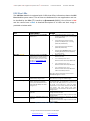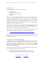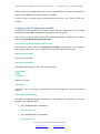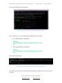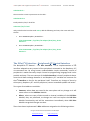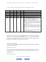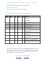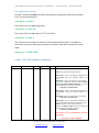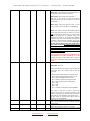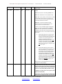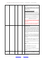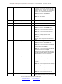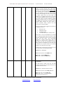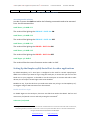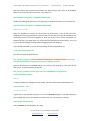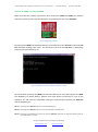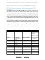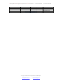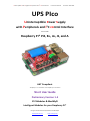
1
Uninterruptible Power Supply with Peripherals and I2C control Interface Firmware Code 0x25 Print Date: 20.05.2015 UPS PIco Uninterruptible Power Supply with Peripherals and I2C control Interface for use with Raspberry Pi® Pi2, B+, A+, B, and A HAT Compliant “Raspberry Pi” is a trademark of the Raspberry Pi® Foundation Short User Guide Preliminary Version 1.4 © PiModules & ModMyPi Intelligent Modules for your Raspberry Pi® Designed and Manufactured by PiModules and ModMyPi www.pimodules.com www.modmypi.com Uninterruptible Power Supply with Peripherals and I2C control Interface Firmware Code 0x25 Print Date: 20.05.2015 Document Revisions Version Date Modified Pages Modified Sections none Comments 1.0 28/01/2015 none 1.1 28/02/2015 21, 17 Figure 8, Figure 7 Updated new variables 1.2 24/03/2015 21 Figure 3, Figure 8 Updated BAT LED flashing time, according to firmware changes 22 First Public Document Release Updated FAN commands 1.3 14/04/2015 21 Figure 3, Figure 8 Commands updated 22 1.4 20/05/2015 16 Figure 1 0x6A Change I2C address 1.4 20/05/2015 17 Figure 7 0x69 Change I2C address 1.4 20/05/2015 18 Figure 2 0x6B Added more commands to the version Variable related to I2C setup Designed and Manufactured by PiModules and ModMyPi www.pimodules.com www.modmypi.com Uninterruptible Power Supply with Peripherals and I2C control Interface Firmware Code 0x25 Print Date: 20.05.2015 Document Revisions......................................................................................................... 2 Credits ............................................................................................................................. 5 System Overview ............................................................................................................. 6 Introduction ........................................................................................................................... 6 Applications ........................................................................................................................... 7 Features ................................................................................................................................. 7 General Information ........................................................................................................ 8 Mounting UPS PIco on Raspberry Pi® ................................................................................ 8 UPS PIco Jumpers............................................................................................................. 9 UPS PIco Buttons ............................................................................................................. 9 UPS PIco LEDs ................................................................................................................ 11 UPS PIco I/Os ................................................................................................................. 12 UPS PIco Advanced User Appications .............................................................................. 12 Setting-up the I2C interface and RTC............................................................................... 13 The PICo (I2C) Interface - Peripherals I2C Control Interface ............................................... 15 0x69 -> UPS PIco RTC Registers Direct Access Specification ............................................... 16 Accessing 0x69 Varibales ................................................................................................. 16 0x6A ->UPS PIco Module Status Registers Specification ..................................................... 17 Accessing 0x6A Varibales ................................................................................................ 18 0x6B -> UPS PIco Module Commands ................................................................................. 18 Accessing 0x6B Varibales................................................................................................. 24 Setting Up the RaspberryPi® Serial Port for other applications ........................................ 24 UPS PIco Terminal Commands Control (@commands RS232 interface) ............................ 27 Designed and Manufactured by PiModules and ModMyPi www.pimodules.com www.modmypi.com Uninterruptible Power Supply with Peripherals and I2C control Interface Firmware Code 0x25 Print Date: 20.05.2015 Table of Figures Figure 1 UPS PIco Jumpers Usage Table .................................................................................... 9 Figure 2 UPS PIco Buttons Usage Table ................................................................................... 10 Figure 3 UPS PIco LEDs Usage Table ........................................................................................ 11 Figure 4 I2C UPS PIco Interface and Simulated DS1307 Clock detection ................................ 14 Figure 5 UPS PIco Simulated DS1307 Clock sudo bash commands execution ........................ 14 Figure 6 0x69 -> UPS PIco RTC Registers Direct Access Table ................................................. 16 Figure 7 0x6A -> UPS PIco Module Status Registers Specification .......................................... 17 Figure 8 0x6B -> UPS PIco Module Commands ....................................................................... 24 Figure 9 UPS PIco Jumpers ...................................................................................................... 26 Figure 10 Minicom screenshot while the UPS PIco restarts.................................................... 26 Figure 11 TCC @commands set ............................................................................................... 28 Designed and Manufactured by PiModules and ModMyPi www.pimodules.com www.modmypi.com Uninterruptible Power Supply with Peripherals and I2C control Interface Firmware Code 0x25 Credits Designed and Manufactured by PiModules and ModMyPi www.pimodules.com www.modmypi.com Print Date: 20.05.2015 Uninterruptible Power Supply with Peripherals and I2C control Interface Firmware Code 0x25 Print Date: 20.05.2015 System Overview Introduction The UPS PIco is an advanced uninterruptible power supply for the Raspberry Pi® that adds a wealth of innovative power back-up functionality and development features to the innovative microcomputer! The standard UPS PIco is equipped with a 300mAh LiPO battery specially designed to enable safe shutdown during a power cut. Additionally, this can be easily upgraded to the extended 3000mAh version, which enables prolonged use of a Raspberry Pi for up to 8 hours without a power supply connected! The UPS PIco features an embedded measurement system that continuously checks the powering voltage of the Raspberry Pi®. When the cable power on the Raspberry Pi® is absent, insufficient, or the device detects a power failure, the UPS PIco automatically switches to the unit’s battery source. The module then continues to check the voltage on the Pi and switches automatically back to the regular cable supply when power becomes once again available. The UPS PIco is powered and the battery pack intelligently charged via the GPIO pins on the Raspberry Pi®, so no additional cabling or power supply is required. The UPS PIco is designed to be 100% compliant with HAT standards for the Raspberry Pi® B+ and A+, and is mechanically compatible with the original Raspberry Pi® models A and B when an extension header is used. In addition to this, because the UPS PIco requires no external powering and fits within the footprint of the Raspberry Pi®, it is compatible with most cases. The UPS PIco can also be equipped with an optional Infra-Red Receiver which is routed directly to GPIO18 via the PCB. This opens the door for remote operation of the Raspberry Pi®and UPS PIco! Finally, the UPS PIco features an implemented Automatic Temperature Control PWM fan controller, and can be equipped with a micro fan kit, which enables the use of the Raspberry Pi® in extreme conditions including very high temperature environments. Designed and Manufactured by PiModules and ModMyPi www.pimodules.com www.modmypi.com Uninterruptible Power Supply with Peripherals and I2C control Interface Firmware Code 0x25 Print Date: 20.05.2015 Applications UPS PIco is equipped with plenty of features which make it an extremely useful tool for Raspberry Pi® project development. It not only provides powering continuity, but also offers extra user programmable LEDs, sensors, buttons and I/O’s. The unit also features a dedicated 10-bit analogue to digital converter with two channels making it the perfect board for remote and unmanned sensor deployment. These extra features result in the UPS PIco being a superior all-in-one device, perfect for many innovative projects and embedded applications. Features The list of features of the UPS PIco is as follows: Raspberry Pi B+ HAT Compliant Plug and Play Smart Uninterruptible Power Supply (UPS) Integrated LiPO Battery (8-10 Minutes of Power Back-Up) Intelligent Automatic Charger No Additional External Power Required Optional 3000 mAh Battery for 8 Hours Run-Time (Not Included) 5V 2A Power Backup (Peak Output 5V 3A) Integrated Software Simulated Real Time Clock (RTC) with Battery Back-Up File Safe Shutdown Functionality Raspberry Pi B+ Activity Pin PWM fan control (Fan Not Included) 2 User Defined LEDs 2 User Defined Buttons Integrated Buzzer for UPS and User Applications Status Monitoring - Powering Voltage, UPS Battery Voltage and Temperature I2C PICo Interface for Control and Monitoring RS232 Raspberry Pi Interface for Control and Monitoring XTEA Based Cryptography User Software Protection 2 Level Watch-dog Functionality with FSSD and Hardware Reset Raspberry Pi B+ Hardware Reset Button via Spring Test Pin (Not Included) Jumpers for Raspberry Pi B+ Pin Functionality Selection Stackable Header for Add-On Boards Boot Loader for Live Firmware Update Compatible with Intelligent IR Remote Power ON/OFF (PowerMyPi) Integrated ESD-Protected 2 Channel A/D 10 Bit Converters 0-5.2V Integrated ESD-Protected 1-Wire Interface Labeled J8 Raspberry Pi B+ GPIO Pins for Easy Plug & Play Infra Red Receiver Sensor Interface (IR Not Included) Upgradable with PIco Add-on Boards Fits Inside Most Existing Cases Designed and Manufactured by PiModules and ModMyPi www.pimodules.com www.modmypi.com Uninterruptible Power Supply with Peripherals and I2C control Interface Firmware Code 0x25 Print Date: 20.05.2015 General Information The UPS PIco Module uses the 5 VDC and GND pins for powering, and interacts with the Raspberry Pi® through GPIO_GEN22 and GPIO_GEN27. Simple Python script must be running on the Raspberry Pi® that interacts with the UPS PIco Module. The GPIO_GEN22 is used to force the File Safe Shutdown (FFSD) procedure when the UPS PIco Module make it low, and read by the Raspberry Pi®. The GPIO_GEN27 is used by the same Python script and generate a pulse train that is recognized by the UPS PIco Module and interpreted if the Raspberry Pi® is running or not. This approach allows simplifying the design, and cutting the needs to have current measure system on the UPS PIco Module. If the Raspberry Pi® is running (so the pulse train is generated) user can see that the UPS LED on the UPS PIco Module is flashing (fast if cable powered, and slow if battery powered). If the UPS LED is not flashing, it means that the Raspberry Pi® is not running (the Python script is not running). Therefore it is mandatory for a proper use of the UPS PIco Module to have the Python script installed. Due to this implemented feature, the UPS LED flashing functionality, user can by a single view have a knowledge if the Raspberry Pi® is running or not (Hang-up, or Shutdown). It is important to notice that for the proper UPS PIco Module operation it is mandatory to have connected GPIO_GEN27 to the UPS PIco Module trough the FSSDU Jumper, as also installed the picofssd.py script. The GPIO_GEN27 is generating pulse train, that is interpreted by the UPS PIco Module and allows it to recognize different states of Raspberry Pi® powering conditions. Mounting UPS PIco on Raspberry Pi® In order to set up the UPS PIco Module some simple hand work is needed. Please follows the below steps before you start working with it. 1. If needed solder one or both of 3-pins connectors to the I/O 2. Check if all green jumpers are on their places, 3. Remove and save the yelow jumper for future HAT EEPROM programming, this procedure will be provided on www.pimodules.com 4. Put the UPS PIco Module on the top of the Raspberry Pi® without connected LiPO battery and cable power to the Raspberry Pi® 5. Connect the LiPO battery to the UPS PIco Module 6. Enter cable powering to the Raspberry Pi® Designed and Manufactured by PiModules and ModMyPi www.pimodules.com www.modmypi.com Uninterruptible Power Supply with Peripherals and I2C control Interface Firmware Code 0x25 Print Date: 20.05.2015 7. Press the UPSR button in order to set the start up conditions 8. If needed make factory defaults (described later on the following chapters) 9. Wait until the Raspberry Pi® boot up, and then verify the Green UPS LED blinking every 500 ms It is important to be sure that when plugging the UPS PIco Module to the Raspberry Pi® the is not cable power connected to it as also LiPO battery connected to the UPS PIco Module. UPS PIco Jumpers For the Basic operation, UPS PIco Module uses only the 5 VDC and GND pins and interacts with the Raspberry Pi® through GPIO_GEN22 and GPIO_GEN27. Some specialized features require in addition RS232 and I2C. In addition if the 1-wire device and IR Receiver are used, there are directly routed to GPIO_GEN04 and GPIO_GEN18 pins respectively. However these pins if not used with above features (the 1-wire not connected and IR Receiver not soldered) can be freely used as a standard GPIO pins. The RS232, GPIO_GEN22, GPIO_GEN27 and HAT EEPROM are going to the UPS PIco Module trough Jumpers set. Therefore, if user not needs some of them can remove the jumpers and free that pins for other applications. Jumper Descrition Usage Connection RXD0 TXD0 FSSDR FSSDU HATWP RX for RS232 @command for the UPS PIco TX for RS232 @command for the UPS PIco File Safe Shutdown Pin for the Raspberry Pi RUN Pin for the UPS PIco HAT EEPROM Write Protection GPIO_GEN15 GPIO_GEN14 GPIO_GEN22 GPIO_GEN27 EEPROM WP RS232 Receive RS232 Transmit FSSD Raspberry Pi FSSD UPS PIco HAT EEPROM WP Figure 3 UPS PIco Jumpers Usage Table UPS PIco Buttons The UPS PIco Module is equipped with 5 buttons that can be used in various ways. Two of them are dedicated for user applications and can be handled by user through the PICo (I2C) interface or @commands (RS232), all other are specific for various UPS PIco Module functionalities. All of them can be used for some start-up functionalities when UPS PIco Module is reset. A detailed description of all buttons and their usage is provided on below table. Designed and Manufactured by PiModules and ModMyPi www.pimodules.com www.modmypi.com Uninterruptible Power Supply with Peripherals and I2C control Interface Firmware Code 0x25 Print Date: 20.05.2015 Button Description Usage Additional Functionalities RPiR Raspberry Pi Hardware Reset Make Raspberry Pi Hardware Reset when pressed. To be used need installed (soldered) the Gold Plated Reset Pin. NOTE1: Resetting of the Raspberry Pi®, can corrupt files on the SD card if used UPSR UPS PIco Hardware Reset NOTE2: Resetting of the Raspberry Pi®, does not affect the UPS PIco (including PIco RTC) Make UPS PIco Hardware Reset when pressed. NOTE1: Resetting of the UPS PIco does not reset the Raspberry Pi®. FSSD File Safe Shutdown KEYA User Key A KEYB User Key B NOTE2: Resetting of the UPS PIco does reset the simulated RTC to default values. When pressed initiate the File Safe Shutdown Procedure. If used need to have FSSDR Jumper short. If Raspberry Pi®+UPS PIco system battery powered, after FSSD finished UPS PIco will cut the power. Pressed again (need to have installed the Gold Plated Reset Pin for the restart option), start the Raspberry Pi®+UPS PIco system again. Can be used for User Application – Read the 2 status via PICo (I C) or RS232 interface Can be used for User Application – Read the 2 status via PICo (I C) or RS232 interface Figure 4 UPS PIco Buttons Usage Table Designed and Manufactured by PiModules and ModMyPi www.pimodules.com www.modmypi.com NONE When pressed with combination with other buttons activate various start-up functionalities. The procedure is to press first the UPSR button, and then another one, then release the UPSR button and then release the other button (valid for FSSD, KEYA, KEYB). When used with UPSR button, make factory self test, used during boards testing. Not useful for user, as a special test board with spring test pins need to be connected. When used with UPSR button, makes the factory default, and reset the RTC to startup values. When used with UPSR button, invokes the bootloader (light the Red User LED). The bootloader can be invoked also from the PICo interface. Uninterruptible Power Supply with Peripherals and I2C control Interface Firmware Code 0x25 Print Date: 20.05.2015 UPS PIco LEDs The UPS PIco Module is equipped with 6 LEDs that offers information about the UPS PIco Module system status. Two of them are dedicated for user applications and can be handled by the PICo (I2C) interface or @commands (RS232). One of them is Red and the second one is Blue. A detailed description of all LEDs and their usage is provided on below table. LED Description UPS LED - Green Provide information about UPS PIco Module status BAT LED - Orange Usage Provide information about UPS PIco Module Battery Level when system is powered from it or continuously lit when PIco system error occurs. See description “Figure 8 0x6B -> UPS PIco Module Commands” Flashes Normally when system is cable powered and Raspberry Pi® is running (100 ms ON, 500ms OFF) Flashes Slow when system is battery powered and Raspberry Pi® is running (100ms ON, 2000ms OFF) Flashes Fast when FSSD is executed (100ms ON, 200ms OFF) Not light when UPS PIco Module is in Low Powering Mode (LPR) and the Raspberry Pi® is not running. Battery Level > 3.7 V BAT LED not Flash 3.7V <= Battery Level > 3.5 V BAT LED Flashes 100ms ON, 2000ms OFF 3.4V <= Battery Level > 3.5 V BAT LED Flashes 100ms ON, 500ms OFF 3.3V <= Battery Level > 3.4 V BAT LED Flashes 100ms ON, 200ms OFF FSSD is immediately initiated When PIco registers data written to the internal EEPROM LED Lights for 1 seond CHG LED - Green HOT LED - Orange Provide information about UPS PIco Module Battery Charger Status Provide information about UPS PIco Module Temperature. Read both sensors (the embedded SOT23 and the PIco FAN Kit TO092) and shows the higher one. LED RED - PLCC2 size Provided for UPS PIco Module User Application LED BLUE - PLCC2 size Provided for UPS PIco Module User Application It is valid only when cable powering is present. When battery is charged the CHG LED Lights. When system temperature is higher than threshold the HOT LED lights. The temperature is measured on both sensors the SMD placed on the top as also on the TO-92 is PIco FAN Kit is used. The higher temperature on one of them activates the HOT LED, and remains until both sensors have lower temperature than the threshold. The default value is 42 Degs Celsius. Available for user application. Handled by the PICo and @commands interface. During Boot Functionalities support interaction with various lightings Available for user application. Handled by the PICo and @commands interface. During Boot Functionalities support interaction with various lightings Figure 5 UPS PIco LEDs Usage Table Designed and Manufactured by PiModules and ModMyPi www.pimodules.com www.modmypi.com Uninterruptible Power Supply with Peripherals and I2C control Interface Firmware Code 0x25 Print Date: 20.05.2015 UPS PIco I/Os The UPS PIco Module is equipped with 4 I/Os, there are: 1-wire interface 10 bits A/D converter 1 (0 - 5.2V) 10 bits A/D converter 2 (0 - 5.2V) IR Receiver The 1-wire interface is supported with supply of 3.3V (which is independent from the Raspberry Pi® powering) and GND on the same connector. It simplifies the connection making when the 1-wire is used. In addition the 1-wire interface is ESD protected. Is is directly routed to the GPIO_GEN04. If the 1-wire sensor is not used the GPIO can be used for any other application on the J8 pins. It contains just the required 4K7 resistor connected to the 3.3V. The UPS PIco Module supports also pre-calibrated 2 x 10 bits A/D converters. Their readings can be easy accessed easy via PICo (I2C) interface or @commands (RS232). Read values are in mV. Those inputs are also ESD protected. The IR Receiver if assembled (soldered on the PCB) is directly routed to the GPIO_GEN18. A very good tutorial how to use it can be found on below link: https://www.modmypi.com/blog/raspberry-pis-remotes-ir-receivers User does not need to add any other component in order to use the IR Receiver. If the IR Receiver is not used (not soldered to the PCB) the GPIO_GEN18 can be used for any other application. UPS PIco Advanced User Appications The UPS PIco Module uses the 5 VDC and GND pins for powering, and interacts with the Raspberry Pi® through GPIO_GEN22 and GPIO_GEN27. Simple Python script is mandatory to be running on the Raspberry Pi® that interacts with the UPS PIco Module. After installing of that Python script there is no real need for any additional tasks to use the UPS PIco Modules. However, there is a group of users that have more advanced needs. In order to cover them 2 different interfaces have been implemented: The Peripherals I2C Control (PICo) Interface, based on the I2C, and The Terminal Commands Control (TCC) Interface, based on the RS232 Designed and Manufactured by PiModules and ModMyPi www.pimodules.com www.modmypi.com Uninterruptible Power Supply with Peripherals and I2C control Interface Firmware Code 0x25 Print Date: 20.05.2015 Both of them are independent and can be used sepratelly. In order to use both of them, a some additional installion works is needed. In order to use I2C and RTC (that is communicating with OS via I2C), a simple I2C set up is needed. Setting-up the I2C interface and RTC The I2C Ports on the Raspberry Pi® are not enabled by default. Follow these steps to enable the I2C ports and the RTC communicate with RaspberryPi® trough I2C. First of all, the config file must be edited that by default disables the I2C port. This setting is stored in /etc/modprobe.d/raspi-blacklist.conf. sudo nano /etc/modprobe.d/raspi-blacklist.conf Once this file is open, find the line blacklist i2c-bcm2708 and comment it out by adding a hash character (#) in front of it as shown here below, then save and close the file. #blacklist i2c-bcm2708 Now edit /etc/modules: sudo nano /etc/modules and add the following lines, then save and close the file. i2c-bcm2708 i2c-dev rtc-ds1307 Reboot the system: sudo reboot Install I2C tools by running the following command (assuming that you're connected to Internet) sudo apt-get install i2c-tools Now look for ID #68 with i2cdetect. Depending on the model of your Raspberry Pi, this must be done in two different ways: On a 256MB Raspberry Pi Model A+: sudo i2cdetect –y 0 On a 512MB Raspberry Pi Model B+: sudo i2cdetect –y 1 Designed and Manufactured by PiModules and ModMyPi www.pimodules.com www.modmypi.com Uninterruptible Power Supply with Peripherals and I2C control Interface Firmware Code 0x25 Print Date: 20.05.2015 The result should look like the following: Figure 6 I2C UPS PIco Interface and Simulated DS1307 Clock detection Then, running as root, do the following (also depending on the model) On a 256MB Raspberry Pi Model A+: sudo bash echo ds1307 0x68 > /sys/class/i2c-adapter/i2c-0/new_device exit On a 512MB Raspberry Pi Model B+: sudo bash echo ds1307 0x68 > /sys/class/i2c-adapter/i2c-1/new_device exit The result should look like: Figure 7 UPS PIco Simulated DS1307 Clock sudo bash commands execution Then check for time from the clock (which will show Sat 01 Jan 2000 if it is the first time that it is used): Designed and Manufactured by PiModules and ModMyPi www.pimodules.com www.modmypi.com Uninterruptible Power Supply with Peripherals and I2C control Interface Firmware Code 0x25 Print Date: 20.05.2015 sudo hwclock -r Then write the current system time to the clock: sudo hwclock -w Finally edit the /etc/rc.local file: sudo nano /etc/rc.local and just before the line that reads exit 0, add the following two lines, then save and close the file: On a 256MB Raspberry Pi Model A+: echo ds1307 0x68 > /sys/class/i2c-adapter/i2c-0/new_device hwclock -s On a 512MB Raspberry Pi Model B+: echo ds1307 0x68 > /sys/class/i2c-adapter/i2c-1/new_device hwclock -s The PICo (I2C) Interface - Peripherals I2C Control Interface The Peripherals I2C Control – The PICo Interface – is an implementation of I2C interface adapted to easy control of the peripheral connected to the Raspberry Pi® via command line. By using human understandable simple commands, control of peripherals is made extremely simple. Control at programming language level is also possible and easy. The core concept of the PICo interface is that all peripheral device control and data exchange between it and Raspberry Pi® variables are common for the I2C interface as also for the peripheral itself. Therefore any change of them by either party, Raspberry Pi® and the peripheral, causes immediate update and action. Two types of variables are available: Common, where data are stored in the same place and any change on it will cause action on the UPS PIco Module Mirror, where are copy of data stored on internal variables of the UPS PIco Module, they are protected, so changes on it will not implies the UPS PIco Module functionality and will be overwritten immediately when UPS PIco Module recognized changes on them There have been implemented 3 PICo addresses assigned to the following entities: Designed and Manufactured by PiModules and ModMyPi www.pimodules.com www.modmypi.com Uninterruptible Power Supply with Peripherals and I2C control Interface Firmware Code 0x25 Print Date: 20.05.2015 0x6A -> UPS PIco RTC Registers Direct Access Specification Address Name Size Type R/W Explanation 0 or 0x00 1 or 0x01 2 or 0x02 3 or 0x03 4 or 0x04 5 or 0x05 6 or 0x06 7 or 0x07 Seconds Minutes Hours DOW Days Month Year RTCCF Byte Byte Byte Byte Byte Byte Byte Byte Mirror Mirror Mirror Mirror Mirror Mirror Mirror Common Read Read Read Read Read Read Read R/W Seconds in BCD Minutes in BCD Hours in BCD DOW in BCD Days in BCD Month in BCD Year in BCD Real Time Clock Correction Factor in HEX Change the RTC timer for multiples of 1 tick per second Timers tick is 1/32768 Hz= 0,000030517578125 sec Write: 0x00 or 0x80 not change the RTC tick Write: 0x01 – 0x79 change the RTC tick by subtract tick multiplication from the standard timer values, therefore it will decrease the “duration” of each second by multiple value of timer ticks – counted second will be shorter, so RTC will be running faster Write: 0x81 – 0xFF change the RTC tick by adding tick multiplication to the standard timer values, therefore it will increase the “duration” of each second by multiple value of timer ticks – counted second will be longer, so RTC will be running slower Adding or subtract of one tick change the 24 hours RTC by 86400 * 0,000030517578125 sec = 2,63671875 seconds Read: Checks actual RTCCF Value Figure 8 0x6A -> UPS PIco RTC Registers Direct Access Table Access to these variables can be done indepened if the RTC is used by the Raspberry Pi(R) system. The last variable is Common changes of it trim the RTC accuracy according to specifications provided in above table. Therefore writting to this register cause immediate action and trimming of the RTC. Accessing 0x69 Varibales In order to access the 0x6A variavbles the following commands need to be executed form the OS command line sudo i2cget -y 1 0x6A 0 The result wil be the seconds register value of the implemented RTC. There are a very good python script and “C” software that showing how to access them, on our products forum. sudo i2cget -y 1 0x6A 1 Designed and Manufactured by PiModules and ModMyPi www.pimodules.com www.modmypi.com Uninterruptible Power Supply with Peripherals and I2C control Interface Firmware Code 0x25 Print Date: 20.05.2015 The result wil be the minutes counter of the implemented RTC. sudo i2cset -y 1 0x6A 7 0x01 The result will set the RTCCF trimming RTC factor to 1. 0x69 ->UPS PIco Module Status Registers Specification Address 0 or 0x00 Name mode Size Byte Type Mirror R/W Read Explanation Powering Mode – Read ONLY, Writing has no effect on the system and will be overwritten by UPS PIco with the new value 0x01 - RPI_MODE 0x02 - BAT_MODE 1 or 0x01 3 or 0x03 5 or 0x05 7 or 0x07 9 or 0x09 10 or 0x0A 11 or 0x0B 12 or 0x0C 13 or 0x0D th Means value of Battery Voltage in 10 of mV in BCD format value of Voltage supplying RPi on J8 5V Pin in rpilevel Word Mirror Read Means th 10 of mV in BCD format value of Voltage supplying USB on P1 5V Pin in AD1Vlevel Word Mirror Read Means th 10 of mV in BCD format value of Voltage supplying EPR on P1 5V Pin in AD2Vlevel Word Mirror Read Means th 10 of mV in BCD format KEYA Byte Mirror R/W Contain 0x01 if KEYA is pressed, and remain until will write back with 0x00. User need to write 0x00 alwayes after reading it. Non pressed KEYA is 0x00, pressed KEYA is 0x01 KEYB Byte Mirror R/W Contain 0x01 if KEYB is pressed, and remain until will write back with 0x00. User need to write 0x00 alwayes after reading it. Non pressed KEYB is 0x00, pressed KEYB is 0x01 KEYF Byte Mirror R/W Contain 0x01 if KEYF is pressed, and remain until will write back with 0x00. User need to write 0x00 alwayes after reading it. Non pressed KEYF is 0x00, pressed KEYF is 0x01 tmpcels Byte Mirror R/W Temperature in Celcius degree of the SOT-23 sensor placed on the top of PCB. Values in BCD format. tmpcelt Byte Mirror R/W Temperature in Celcius degree of the TO-92 sensor placed on the bottom of PCB. It is valid only if this sensor is soldered. It is available in the PIco Fan Kit. Values in BCD format. Figure 9 0x69 -> UPS PIco Module Status Registers Specification batlevel Word Mirror Read Access to those variables offers information about UPS PIco Modules status and their peripherals. All of them are mirror so are available for reading. However the KEYA, KEYB and KEYF need to be “reseted” (by writting 0x00) after reading in order to prepare them for the next key pressed status. Designed and Manufactured by PiModules and ModMyPi www.pimodules.com www.modmypi.com Uninterruptible Power Supply with Peripherals and I2C control Interface Firmware Code 0x25 Print Date: 20.05.2015 Accessing 0x69 Varibales In order to access the 0x69 variavbles the following commands need to be executed from the OS command line sudo i2cget -y 1 0x69 0 The result wil be the powering mode sudo i2cget -y 1 0x69 5 w The result wil be the AD1 value in 10th of milivolts sudo i2cget -y 1 0x69 9 The result wil be the status of the KEYA and if presed with be 0x01, if not 0x00. IN case that the result is 0x01 (key pressed) this variable need tobe reseted by writting 0x00. sudo i2cset -y 1 0x69 9 0x00 0x6B -> UPS PIco Module Commands Address 0 or 0x00 Name version Size Byte Type Common R/W R/W Explanation Version.Factory.Reset.FSSD. Bootloader.I2C Read: Check the actual firmware Version Write: 0xa0 – Set the I2C Addesses Registeres to I2C_NORMAL where the following adresses are used: 68 69 6a 6b – defined for all functions of UPS PIco 6c 6d 6e 6f– defined for functions related to Event Driven Time Based ON/OFF Scheduler of UPS PIco and will be defined in next version of firmware sudo i2cset -y 1 0x6b 0 0xa0 Write: 0xa1 – Set the I2C Addesses Registeres to I2C_MINIMAL where the following adresses are used: 68 69 6a 6b – defined for all functions of UPS PIco sudo i2cset -y 1 0x6b 0 0xa1 Write: 0xa2 – Set the I2C Addesses Registeres to I2C_NORTC where the following adresses are used: 6A 6b – defined for all functions of UPS PIco Releases the 0x68 and 0x6A of the internal RTC and give it for other additional RTC devices sudo i2cset -y 1 0x6b 0 0xa2 Each change of the I2C configuration cause UPS PIco Restart. Default Value is 0xA1 - MINIMAL Designed and Manufactured by PiModules and ModMyPi www.pimodules.com www.modmypi.com Uninterruptible Power Supply with Peripherals and I2C control Interface Firmware Code 0x25 Print Date: 20.05.2015 Write: 0xcc – Unconditional File Safe Shutdown and (and Power OFF when battery powered) Write: 0xdd - then restore factory defaults Will stay in the values of 0xdd until factory defaults restored, and then will be set to version of the firmware. Write: 0xee - Reset the UPS PIco CPU, it cause start-up values i.e. RTC will be set to 01/01/2000 Write: 0xff - Call the UPS PIco Bootloader, RED Led will be light. Recover from this state can be done only by pressing the RST button or new firmware upload. All interrupts are disabled during this procedure. It should be used with RPi Uploading firmware script. Use it very carefully and only when is needed – when firmware uploading. Do not play with it; this is not a toy functionality. Powering of the pair UPS PIco+RPi must be done via RPi micro USB socket during boot loading process due to following UPS PIco Resets after firmware uploading or when returning from this mode. The UPS functionality as also all others is not working when entering this mode. 1 or 0x01 error_code Byte Mirror Read Due to required protection for the RPi from the unconditional reset (files corruption), it is not possible to enter to this mode when system is powered in a different way than in RPI Powering Mode. UPS PIco System Error Code Read: 0x00 – No error If UPS PIco System Error happens, then the BAT LED continously light until wrong conditions will be corrected Each Bit of this variable represent a specific error: Bit 0 – RPi Powering Voltage lower than 4.7V Bit 1 – Battery Voltage lower than 3.3V Bit 2 – Battery Temperature higer than 50 C Bit 3 – UPS PIco System watch-dog restart Bit 4 – TBS Bit 5 – TBS Bit 6 – TBS Bit 7 – ON when writting data to PIco EEPROM 2 or 0x02 rpi_serror Word Mirror Read 4 or 0x04 bat_serror Word Mirror Read 6 or 0x06 tmp_serror Word Mirror Read User action is required in order to cancel the System Error Code, by writting the 0x00 to this register. If System Error still exists will be overriten again with its code. UPSR clear this register value. No User action is required when when data are writting to the PIco EEPROM Means value of Voltage supplying RPi on J8 5V Pin th in 10 of mV in BCD format when UPS PIco System Error happen th Means value of Battery Voltage in 10 of mV in BCD format when UPS PIco System Error happen Meana value of Battery Sensor Temperature in BCD Designed and Manufactured by PiModules and ModMyPi www.pimodules.com www.modmypi.com Uninterruptible Power Supply with Peripherals and I2C control Interface 8 or 0x08 sta_counter Byte Common R/W Firmware Code 0x25 Print Date: 20.05.2015 format (Celcius Degrees) when UPS PIco System Error h appen Still Alive Timeout Counter in seconds in HEX format Read: Anytime, Return actual sta_counter value Write: 0xff – Disable the counter (default value) Write: 0x01 – 0xfe Enable and start down counting of the Still Alive Time Counter in resolution of 1 second, until reaches value of 0x00 which initiate the File Safe Shutdown Procedure Write:0x00 – Initiate immediately File Safe Shutdown Procedure and system restart with similar conditions as described below In order to use it as Still Alive (type of watchdog) timer, user needs to upload value from 0x01 to 0x0fe earlier than defined time of seconds. Not uploading of this value will cause System File Safe Shutdown after time out. The maximum time out is 254 second. 9 or 0x09 fssd_batime Byte Common R/W 1. When Cable Powering is connected and Gold Plated Reset Pin is installed, then first try is to execute FSSD, and after that hardware reset by setting LOW on the Raspberry Pi RUN pin for 250 ms is followed. If Gold Plated Reset Pin is not installed, the hardware reset will be not executed. That means the Raspberry Pi will not reset, if hangs up. So System will not restart again. 2. When Cable Powering is disconnected (system is powered via PIco battery) and Gold Plated Reset Pin is installed, then first will try is to execute FSSD, and after that hardware reset by setting LOW on the Raspberry Pi RUN pin for 250 ms is followed. If Gold Plated Reset Pin is not installed, the hardware reset will be not executed however the battery powering will be cutted for 250 ms. That means the Raspberry Pi will reset, if hangs up. So System will restart again. After execution of the STA Restart the sta_counter is set again to 0xFF (disabled). Battery Running Time when cable power loses. After that time a File Safe Shut Down Procedure will be executed and System will be shutdowned without restart. Battery power will be diconected. System is in sleep mode (LPR) aqnd RTC is runing. If Raspberry Pi cable power returns again system will be start automaticly. If during the sleep mode (LPR) the FSSD button will be presed for longer time than 2 seconds (with Designed and Manufactured by PiModules and ModMyPi www.pimodules.com www.modmypi.com Uninterruptible Power Supply with Peripherals and I2C control Interface Firmware Code 0x25 Print Date: 20.05.2015 battery or cable powering) Raspberry Pi will restart again. Value of 0xff (255) disable this timer, and system wil be running on battery powering until battery discharge to 3.5 V. Factry default value is 120 seconds Value higher than 15 seconds are only accepted Writting of smaller value than 15 seconds to this register, wil be overwritten with 30 seconds (0x14) Read: Anytime, Return actual fssd_timeout value Write: 0x14 – UPiS will cut the power after FSSD (default value) – 30 seconds Must be bigger than 15 seconds (0x0F), if smaller is set, then automatically will be selected the default value Any change on this register will cause immediate writting of the new value to the PIco EEPROM 10 or 0x0A lprsta Byte Common R/W Low Power Restart Time in seconds in HEX format (from 0x01 – 0xff) This is the timer which counts how often the power will be checked in Low Powering Mode in order to restart the system. Default value is 5 seconds. More often checking means faster response to power come back, however consumes more power from the battery. Less often means slower response to power come back, however consumes less power from battery. Default value is 5 seconds. This means that when cable power return, it will be recognized within maximum 5 seconds and switch ON the UPS PIco. The same timer is used also for the button presses restart RPi. The RPi+UPS PIco system will go to the Low Powering Mode (LPR) after the lprsta timer value. This is valid in all cable powering modes, except of the RPi mode. 0x00 is not allowed and will be ignored by the system Write: 0x01 – 0xff set the time in seconds Read: Anytime, Return actual lprsta value Value of the lprsta will be stored in the UPS PIco EEPROM 11 or 0x0B btto Byte Common R/W Battery Powering Testing Timeout This is timer that force the UPS PIco when battery powered to check if cable power returns. Default it is 5 seconds. So, when UPS PIco+RPi are powered Designed and Manufactured by PiModules and ModMyPi www.pimodules.com www.modmypi.com Uninterruptible Power Supply with Peripherals and I2C control Interface Firmware Code 0x25 Print Date: 20.05.2015 from battery, every 5 seconds the UPS PIco checks if powering cable has been entered (the RED RPi LED flashes then), and if yes then switch off the battery, and after 2 seonds start up the battery charger, if not - continoue battery powering. Read: Anytime, Return actual btto value Write: 0xff – Not allowed Write: 0x01 – Not allowed 12 or 0x0C led_blue Byte Common R/W 13 or 0x0D led_red Byte Common R/W 14 or 0x0E bmode Byte Common R/W Write: 0x02 – 0xfe time in seconds LED BLUE - PLCC2 size ON - Write: 0x01 LED BLUE - PLCC2 size OFF - Write: 0x00 LED RED - PLCC2 size ON - Write: 0x01 LED RED - PLCC2 size OFF - Write: 0x00 Integrated Buzzer Mode Read: Anytime, Return actual bmode value Write: 0x00 – Unconditional Disable the buzzer Write: 0x01 – Unconditional Enable the buzzer Write: 0x02 – Enable Automatic buzzer functionality – beep only when is defined in the firmware 15 or 0x0F fmode Byte Common R/W UPS PIco restarts alwayes with automatic Buzzer Mode Integrated Fan Running Mode Read: Anytime, Return actual fmode value Write: 0x00 – Unconditional Disable the FAN with selected speed from the fspeed Write: 0x01 – Unconditional Enable the FAN FAN with selected speed from the fspeed When UPS PIco is gowing down to the LPR mode, the FAN is automaticly disabled, and enabled again when the UPS PIco returns to normal work 16 or 0x10 fspeed Byte Common R/W Integrated Fan Speed Read: Anytime, Return actual fspeed value Write: 0x00 – Selected speed when ON is 0% (not running) Write: 0x01 – Selected speed when ON is 100% (full speed running) Write: 0x02 – Selected speed when ON is 25% Write: 0x03 – Selected speed when ON is 50% Write: 0x04 – Selected speed when ON is 75% 23 or 0x17 XBMC Byte Common R/W Activate XBMC Mode Added XBMC functionality, running without python Designed and Manufactured by PiModules and ModMyPi www.pimodules.com www.modmypi.com Uninterruptible Power Supply with Peripherals and I2C control Interface Firmware Code 0x25 Print Date: 20.05.2015 script needs, especially addressed for XBMC users. System is running normally when cable power connected and when cable power removed, system will stops (cut the battery power without FSSD) after specified time out (60 seconds). During this time the Raspberry Pi will shut down by itself forced by the Pulse-Eight CEC driver. Reconnecting the power (switch ON TV) starts again the Raspberry Pi. The XBMC functionality is also useful for any other application when user would like to have a full control of system shutdown without assigning any GPIO for that. On such applications (non XBMC) user will need to monitor the I2C Powering Mode Variable and when switch to battery shutdown within required time (60 seconds). Not needed for XBMC. During this mode all other triggers for the FSSD are not working. There are: Still Alive Timer FSSD when button Low Battery FSSD Timed FSSD UPS when in battery mode When power is cut from the Raspberry Pi, the UPS PIco is entering the LPR mode, and recover is done only when cable power is back. The RTC is running during that LPR mode. This functionality implements a perfect media player, when the Raspberry Pi is powered from a USB from the TV. Then when TV is OFF, the Pulse-Eight CEC driver safety shutdown the Raspberry Pi, and after that the UPS PIco cut the power. When TV is switched ON again, the media player starts again. Combining this mode with IR mounted give to the user a full remote controlled Media Player Default value is: 0x00 (OFF) Read: Anytime, Return actual XBMC value Write: 0x01 – Activate XBMC Mode Write: 0x00 – deActivate XBMC Mode 24 or 0x18 FSSD_tout Byte Common R/W Set the timeout needed for the FSSD procedure to be completed The FSSD timeout specify how long the FSSD procedure will takes long. The FSSD timeout cannot be smaller than 32 seconds. Default value is: 0x20 seconds (32 seconds) Read: Anytime, Return actual FSSD_tout value Write: 0x2d – 0xff – Set the FSSD_tout Write: 0x00 – 0x2d – not allowed, will be overwritten with default value Designed and Manufactured by PiModules and ModMyPi www.pimodules.com www.modmypi.com Uninterruptible Power Supply with Peripherals and I2C control Interface Firmware Code 0x25 Print Date: 20.05.2015 Figure 10 0x6B -> UPS PIco Module Commands Accessing 0x6B Varibales In order to access the 0x6B variavbles the following commands need to be executed from the OS command line sudo i2cset -y 1 0x6B 12 1 The result will be lighting the LED BLUE - PLCC2 size ON sudo i2cset -y 1 0x6B 12 0 The result will be lighting the LED BLUE - PLCC2 size OFF sudo i2cset -y 1 0x6B 13 1 The result will be lighting the LED RED - PLCC2 size ON sudo i2cset -y 1 0x6B 13 0 The result will be lighting the LED RED - PLCC2 size OFF sudo i2cget -y 1 0x6B 0 The result will be the current firmware version code i.e. 0x0F Setting Up the RaspberryPi® Serial Port for other applications By default Raspberry Pi®’s serial port is configured to be used for console input/output. While this is useful if you want to log in using the serial port, it means that you can't use the Serial Port in your programs. To be able to use the serial port to connect and talk to other devices, the serial port console logins need to be disabled. Needless to say, if you do this then you need some other way to log in to the Raspberry Pi®; we suggest using an SSH connection over the network. Disable Serial Port Login To disable logins on the serial port, there are two files that need to be edited. The first and main one is /etc/inittab. You can edit it by issuing this command1: sudo nano /etc/inittab 1 throughout this manual we will assume that text files are edited with nano and that the user knows how to save the file, after editing. However, instead of nano the user is free to use any other text editor that he or she feels comfortable with. Designed and Manufactured by PiModules and ModMyPi www.pimodules.com www.modmypi.com Uninterruptible Power Supply with Peripherals and I2C control Interface Firmware Code 0x25 Print Date: 20.05.2015 This file contains the command that enables the login prompt, that needs to be disabled. Move to the end of the file: you will see a line similar to: T0:23:respawn:/sbin/getty -L ttyAMA0 115200 vt100 Disable it by adding a # character to the beginning, as shown here below, then save the file. #T0:23:respawn:/sbin/getty -L ttyAMA0 115200 vt100 Disable Boot-up Info When the Raspberry Pi® boots up, all the boot log information is sent to the serial port. Disabling this boot log information is optional and you may want to leave this enabled as it is sometimes useful to see what happens at boot and if you have a device connected (i.e. Arduino) at boot, you might want it to receive this information over the serial port, so it is up to you to decide whether to keep this boot logging enabled or disable it. If you decide to disable it, you can do it by editing the file /boot/cmdline.txt: sudo nano /boot/cmdline.txt The content of the file looks like this dwc_otg.lpm_enable=0 console=ttyAMA0,115200 kgdboc=ttyAMA0,115200 console=tty1 root=/dev/mmcblk0p2 rootfstype=ext4 elevator=deadline rootwait Remove all references to ttyAMA0 (which is the name of the serial port), then save the file and close it. The file will now look like this: dwc_otg.lpm_enable=0 console=tty1 root=/dev/mmcblk0p2 rootfstype=ext4 elevator=deadline rootwait Reboot In order to enable the changes you have made, you will need to reboot the Raspberry Pi: sudo shutdown -r now Test the Serial Port A great way to test out the serial port is to use the minicom program. If you don’t have this one installed and you are connected to Internet, then you can install it by running sudo apt-get install minicom Run up minicom on the Raspberry Pi® using Designed and Manufactured by PiModules and ModMyPi www.pimodules.com www.modmypi.com Uninterruptible Power Supply with Peripherals and I2C control Interface Firmware Code 0x25 Print Date: 20.05.2015 minicom -b 38400 -o -D /dev/ttyAMA0 Make sure that the jumpers required for serial connection (RXD0 and TXD0) are installed and that no other boards using the serial port are placed on the top of the UPS PIco. Figure 11 UPS PIco Jumpers By pressing the UPSR (the UPS Reset Button) you should see on the minicom screen the UPS PIco welcome message after reset. This will ensure you that the UPS PIco is cooperating properly with your Raspberry Pi ®. Figure 12 Minicom screenshot while the UPS PIco restarts Be careful when pressing the UPSR (the UPS Reset Button) to avoid pressing also the RPIR (the Raspberry Pi® Reset Button), because that other button would force a reset of the Raspberry Pi® and cause the immediate cutting of communication between the UPS PIco and the Raspberry Pi®. NOTE1: Resetting of the UPS PIco does not reset the Raspberry Pi®. NOTE2: Resetting of the UPS PIco does reset the simulated RTC to default values. NOTE3: Resetting of the Raspberry Pi® does not reset the UPS PIco, therefore the RTC keeps working and the time information is not lost. Designed and Manufactured by PiModules and ModMyPi www.pimodules.com www.modmypi.com Uninterruptible Power Supply with Peripherals and I2C control Interface Firmware Code 0x25 Print Date: 20.05.2015 NOTE4: Resetting of the Raspberry Pi® is possible only if the Reset Gold Plated Pin is installed (soldered). UPS PIco Terminal Commands Control (@commands RS232 interface) The UPS PIco Module uses the 5 VDC and GND pins for powering, and interacts with the Raspberry Pi® through GPIO_GEN22 and GPIO_GEN27. Simple Python script must be running on the Raspberry Pi® that interacts with the UPS PIco Module. After installing of that Python script there is no need for any additional tasks to use the UPS PIco Modules. However, there is a group of users that have more advanced needs. The Terminal Commands Control was specifically addressed for them and is an alternative way for advanced controll of the UPS PIco Module other than PICo (I2C) Interface. There are plenty of commands for full system control. Thanks to the implemented bootloader, the set of commands can be constantly enhanced with new ones, as we release more of them. We are open to customer suggestions about new commands to implement. Customers can propose new commands by e-mail or on our forum: if we find them generally useful, then we will implement them for free and distribute them via our bootloader system. Customized versions of the firmware featuring customer-specific commands are also possible. Command Meaning Explanation - Usage Action @factory Factory Defaults @factory or @FACTORY @version Firmware and Hardware Release Version Status of the System @version or @VERSION Return UPS PIco to Factory Default Values. Should be used always after upload of a new firmware. Executing of this command does not reset the Raspberry Pi, so can be used when powered from battery Return UPS PIco Hardware and Firmware Version Read First A/D converter Read Second A/D converter Powering Mode Value of the Battery Level Value of the J8 5V Level @ad1 or @AD1 @time PIco RTC Time @time or @TIME @date PIco RTC Date @date or @DATE @beep Beep @beep or @BEEP @status @ad1 @ad2 @pm @bat @rpi @status or @STATUS @ad2 or @AD2 Return the second A/D converter value in mili volts @pm or @PM @bat or @BAT Return the Powering Mode @rpi or @RPI Return the 5V on J6 connector Level value in mili volts Return the time of the PIco RTC Return the date of the PIco RTC Make “beep” on integrated buzzer Designed and Manufactured by PiModules and ModMyPi www.pimodules.com Return UPS PIco system status Return the first A/D converter value in mili volts www.modmypi.com Return the Battery Level value in mili volts Uninterruptible Power Supply with Peripherals and I2C control Interface @redon @redoff @blueon @blueoff RED LED ON RED LED OFF BLUE LED ON BLUE LED OFF Firmware Code 0x25 @red on or @RED ON @red off or @RED OFF @blue on or @BLUE ON @blue off or @BLUE OFF Figure 13 TCC @commands set Designed and Manufactured by PiModules and ModMyPi www.pimodules.com www.modmypi.com Print Date: 20.05.2015 Make RED LED ON Make RED LED OFF Make BLUE LED ON Make BLUE LED OFF