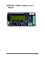
1
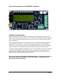
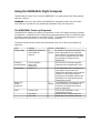
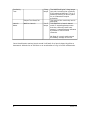
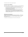
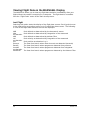
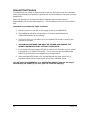
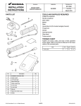
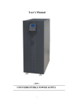
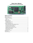
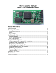
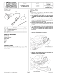
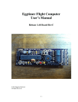
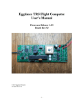
MARSA54L Flight Computer User’s
Manual
1
Version 1.4
Table of Contents
MARSA54L Flight Computer User’s Manual..................................................................1
Latest Documentation............................................................................................ 3
Disclaimer of Liability............................................................................................. 4
Important Safety Information.................................................................................4
Output Device Selection........................................................................................4
Continuity testing hazards.....................................................................................4
Barometric Sensor Sunlight Sensitivity..................................................................5
Starting motors with the MARSA............................................................................5
Physical Description of the MARSA54L Hardware...................................................6
Installation and Mounting......................................................................................6
Using the MARSA54L Flight Computer..........................................................................7
The MARSA54L Power-up Sequence.......................................................................7
Programming the MARSA54L Flight Computer.............................................................9
Apogee...................................................................................................................... 9
Altitude..................................................................................................................... 9
Timer........................................................................................................................ 9
Timer-MTR................................................................................................................ 9
Programming Procedure......................................................................................10
Using the Marsa54L Programming Presets...........................................................11
Setting the Altimeter Tone Frequency.................................................................11
Altitude Lockout Option for Airstarts....................................................................11
Diagnostic Features................................................................................................... 12
Diagnostic Menu..................................................................................................12
Sensors................................................................................................................ 12
Outputs................................................................................................................ 12
Testing the Output MOSFETs...............................................................................13
Calibrating the Accelerometer.............................................................................13
Viewing Flight Data on the MARSA54L Display...........................................................15
Last Flight............................................................................................................ 15
Ground Test Feature.................................................................................................. 16
Procedure to activate the flight simulator...............................................................16
Connection to a Computer......................................................................................... 17
MARSA Connect Program.....................................................................................17
Connecting to the MARSA54L..............................................................................17
............................................................................................................................ 19
Updating MARSA Firmware..................................................................................20
2
Version 1.4
Copyright 2014 Marsa Systems Inc.
www.marsa4.com
Latest Documentation
It is likely that this printed documentation may be out of date. Download the most
current version of user documentation and software from the MARSA4 website.
www.marsa4.com
3
Version 1.4
Disclaimer of Liability
The MARSA series of altimeters are EXPERIMENTAL electronic components. The
device output features of the altimeter are provided to the user for experimental use
only. It is the SOLE responsibility of the user/experimenter to use proper design and
testing practices to safely integrate the altimeter into the test vehicle. The
experimenter must be aware of potential failure modes of the MARSA altimeter,
which may include the failure to fire an attached device or fire an attached device
prematurely or late and accept those risks. It is the responsibility of the
experimenter that safety is maintained even with these and other potential failure
modes.
Marsa Systems Inc. shall not be liable for any special, incidental, or consequential
damage or expense directly or indirectly arising from the customer or anyone’s use,
misuse, or inability to use this device either separately or in combination with other
equipment or for personal injury or loss or destruction of other property, for
experiment failure, or for any other cause.
Do not use this device unless you completely understand and agree with all the
above statements and conditions. First time use of the MARSA4 altimeter signifies
the user’s acceptance of these terms and conditions.
Marsa Systems Inc. warrants the MARSA altimeter to be free from defects in
materials and workmanship for 1 year. If the unit fails to operate as specified the
unit will be repaired or replaced. This warranty excludes any malfunction due to
damage from use or flight.
Important Safety Information
Output Device Selection
The MARSA4, MARSA54 and MARSA54L works best with moderate current devices.
The MARSA output circuits are capable of supplying robust current so ultra low
current devices are unnecessary, not recommended and are generally not as safe as
ignition devices with a higher no-fire current level.
Output devices should have a no-fire current greater than 0.2 amps and an all-fire
current less than 2 amps. The MJG J-Tek is an example of a suitable device for use
with the MARSA altimeter line..
Continuity testing hazards
Whenever any altimeter is active in the output circuitry the hazard of an inadvertent
firing is elevated. The MARSA provides a valuable mode where the device resistance
and/or live current carrying capability of the output circuit can be measured. In this
mode a slightly higher current can flow in order to get a more accurate
measurement. For this reason DO NOT MEASURE DEVICE RESISTANCE IN
CONTACT WITH DEPLOYMENT POWDER.
During the power-up launch sequence the altimeter will give 3 long beeps just prior
to when the MARSA will be checking the output circuits for continuity. This will alert
you to be on-guard for an inadvertent device firing.
4
Version 1.4
Barometric Sensor Sunlight Sensitivity
The barometric pressure sensor used in this and many other altimeters is sensitive to
bright light especially sunlight. DIRECT SUNLIGHT ON THE BAROMETRIC
SENSOR DURING FLIGHT MODE IS LIKELY TO TRIGGER A FALSE LAUNCH
DETECT AND OUTPUT TURNING ON. Be very careful when the altimeter is
powered and outside the electronics bay when deployment devices are connected.
Starting motors with the MARSA
NEVER power the MARSA unless the rocket is vertical and stable on the pad when the
altimeter is configured to start a motor.
5
Version 1.4
Physical Description of the MARSA54L Hardware
Installation and Mounting
Mount the altimeter securely with #4 hardware using the 4-holes provided on the
PCB corners. The holes are on 1.65” x 3.70” centers. The altimeter must be mounted
with the long direction parallel with the axis of the rocket. It does not matter which
end is pointing up.
Attach the battery leads to the B- (negative) and B+ (positive) labeled terminals on
the 4-position terminal block. Attach the arming switch leads to the SW labeled
terminals. If you do not use a switch on the altimeter connector connect the battery
negative lead to B- and the battery positive lead to the right-most SW terminal.
A single 9v alkaline, NiMH rechargeable, or 2S (7.4) LiPo battery is all that is required
to operate the MARSA54L and to reliably power commonly used output devices.
Battery voltage should be limited to 11v maximum and must never exceed 12v or
damage to the onboard power supply may result.
Use a high quality switch with the MARSA altimeter. Dirty bouncy power on
and off can cause any altimeter to erratically jump to random program
locations and start executing.
6
Version 1.4
Using the MARSA54L Flight Computer
The best way to learn how to use the MARSA54L is to apply power and start playing
with the controls.
WARNING: Once you get used to the MARSA54L operating system you will find it
very difficult to go back to any traditional altimeters that you may have.
The MARSA54L Power-up Sequence
The MARSA54L displays a wealth of information on the LCD display during the powerup sequence. It replays how the channels are programmed as well as communicating
the status of several power-on self tests (POST). This detailed information is one of
many features that result in a very high system reliability.
The table below lists the events and information that occurs during the power-up
sequence;
Item
Power apply
Display
MARSA54L Altimeter
Ver1 Build XX
Flight X
Channel
programming
Chan1 Apogee
Baro Only
Delay 0.0s
Start in X
Countdown
Begin Prelaunch
sequence
POST
5
beeps
Sensors OK
I2C W OK
I2C R OK
7
Sound
5
beeps
Description
5 beeps to indicate that power has
been applied and the computer
has started. The display indicates
the current firmware version and
the number of flights on the
MARSA54L
Each of the 5 channel program
settings will be displayed in turn.
The MARSA54L will countdown to
zero which at that time the
MARSA54L will begin its pre-launch
sequence. Moving the joystick
during this countdown places the
altimeter into Programming and
Diagnostics mode.
The MARSA54L will beep five times
at the end of the countdown to
indicate it is beginning the prelaunch sequence.
Test of the barometric and
acceleration sensor
Write test of on-board memory
Read test of on-board memory
Version 1.4
Continuity
Test
3 long
beeps
Output Test Pass/Fail
Launch
Mode
Wait for Launch
1 or 2
beeps
The MARSA will give 3 long beeps
just prior to testing the continuity
of the attached devices. This is a
heads-up warning to be on guard
for an inadvertent output
activation.
The result of the continuity test is
displayed.
The MARSA is in launch detect
mode. 2 repeating beeps mean
that the continuity tests have
passed, 1 repeating beep indicates
a problem in one or more
channels.
No Beep in Launch mode means
the battery voltage is too low.
Once the altimeter reaches launch mode it will wait for a launch detect by either a
barometric altitude rise of 300 feet or an acceleration of >2g’s for 300 milliseconds.
8
Version 1.4
Programming the MARSA54L Flight Computer
Programming the MARSA54L is easy and intuitive with the display and joystick. All of
the MARSA54L commands are menu driven from the display. All the menu’s have the
same basic operation. The MARSA54L is placed into programming mode by moving
the joystick while the altimeter is in the countdown period of its start-up sequence.
Each menu ‘page’ has up to 3 lines of menu items. Each line can optionally have 1 or
2 menu options. There is a cursor “>” that is positioned before the menu item that is
active. The cursor is movable by the joystick up, down, left and right to navigate to
other menu items or to toggle through menu options.
The following table lists the events and options that can be programmed for each
channel.
Event
Apogee
Fires channel
when apogee
has been
detected by
the user
selected option
Options 1
Baro Only
Accel Only
Baro OR Accel
Baro AND
Accel
Kalman
Options 2
Delay(0.1s)
Altitude
Timer
Alt
Fm Launch
Fm Burnout
Alt Up
Fm Launch
Fm Burnout
Alt Up
Delay (1s)
Delay(0.1s)
Timer-MTR
Alt
Delay(0.1s)
Alt
Comments
Baro OR Accel and
Kalman are the
recommended
options for flights
under 40K MSL.
Delay is when the
channel will fire in
tenths of a second
after apogee is
detected
Menu
Setup Chan
Timer-MTR is the
same as Timer
except Timer-MTR
does not continuity
test during POST and
will not fire if a fault
is detected pre or
post launch.
To save any changes to the event programming you must navigate back to
the Chan Setup menu with the cursor pointing to “Chan Setup”.
9
Version 1.4
Programming Procedure
1. Enter programming mode by a joystick move while in the countdown period of
the MARSA54L start-up sequence.
2. Select the “Custom Setup” menu.
3. With the cursor pointing to Setup (>Setup) move the joystick to the right to
select the Setup Menu.
4. With the cursor pointing to Chan Setup move the cursor to the right to select
the Chan Setup Menu.
5. The programmed setting for Channel 1 (Chan1) will be displayed on the
screen. With the cursor pointing at Chan1 (>Chan1) moving the cursor down
or up will step through the other Channel settings.
6. To change a channel’s programmed event, move the joystick to the right.
That will move the cursor to point to the channel’s programmed event type.
Each additional joystick move to the right will step through the other event
types.
7. With the cursor pointing to the desired event type for the channel moving the
joystick down will position the cursor to the second line pointing at the first
option for the selected event. Move the joystick right and left to step through
the available options for the event.
8. If the event has a second option it can be changed by moving the joystick
down to select the third line. Moving the joystick right or left changes the
value for the third option.
9. Repeat the above procedure for the other channels by navigating the cursor
back to pointing to ChanX.
10. Finally save the program settings by returning the cursor back to Chan Setup
(>Chan Setup) by simply reversing the joystick navigation.
11. Options in the Advanced Setup Menu (Adv Setup) can be programmed in a
similar manner.
10
Version 1.4
Using the MARSA54L Programming Presets
The Marsa54L programming presets are accessed by through the “Quick Start”
menu. There are four available presets. The first one is READ ONLY and is
programmed with the factory default program.
The options available for each preset are:
• Select one of the four presets by moving the cursor to the preset name and
moving the cursor down to scroll through the presets.
• Save the current altimeter program into the preset.
• Load the program stored in the preset into the altimeter current program.
• Rename the preset by moving the cursor to each character and scrolling
characters by moving the joystick up or down.
Setting the Altimeter Tone Frequency
The Marsa54L beeper's frequency can be adjusted. To adjust the tone select the
“Custom Setup” menu then select “Set Tones” The beeper will beep 3 times. The
frequency can be adjusted by moving the joystick up or down and changing the
number that appears.
Not only does the tone frequency change but the loudness will also change
depending on the resonances of the beeper.
Altitude Lockout Option for Airstarts
When setting a timer for an airstart you can use the “AltitudeUp” option to set an
altitude lockout for airstarts.
For example if you program a timer for an ignition of 1 sec after motor burnout AND
an altitude up value of 1000 feet, the channel will only fire if the altitude has been
achieved when the timer delay has been reached.
11
Version 1.4
Diagnostic Features
The MARSA54L has powerful diagnostic, health check and output device
measurement capabilities not available in other flight computers. It is these easy to
use features that greatly increase the system reliability achieved with the MARSA4.
Diagnostic Menu
Enter the diagnostic menu by moving the cursor to the “DIAG” item and then move
the cursor to the right.
The display will read the battery voltage on the first line followed by “Sensors” and
“Outputs” on the next two lines.
>Power 9.56v
Sensors
Outputs
Sensors
Move the cursor to “Sensors” and select it by moving the joystick to the right. The
barometric sensor and accelerometer voltages will be displayed. Also the calculated
altitude corresponding to the barometric sensor will be displayed on the third line of
the display.
Example:
Baro 3.940v
Accel 2.495v
898 ft
If the indicated altitude is reasonable (within +/- 500 ft of true) then the barometric
sensor can be trusted. Additionally you can place a straw on the barometric sensor
port and suck some vacuum to see if the voltage responds.
The accelerometer voltage reading should be between 2.4 and 2.6v with the MARSA4
level to the ground and it should vary as you tilt the board up and down.
Outputs
The output menu provides the capability to measure the resistance of any attached
devices. This is vastly superior to the more common continuity tests used on
traditional flight computers. In addition the proper operation of the output MOSFETs
can be tested.
Select the Outputs menu by moving the cursor to Outputs and moving the joystick to
the right. If pyro devices are attached the resistance of the attached devices can be
measured by selecting the Continuity menu item.
By moving the joystick again to the right the electrical resistance of the attached
devices will be displayed.
Example:
12
P1=1.3Ω P2=1.1 Ω
P3=N/A P4=N/A
Version 1.4
The resistance should be close to what you expect.
Testing the Output MOSFETs
Make sure no devices are attached to the outputs or you will turn them on!
1. In the Outputs menu page set the cursor to the “Test Outputs” line.
2. Move the cursor to the right, the display will ask “Sure?” to make sure that
you really want to turn the outputs on.
3. Move the joystick to the right again and the LED’s next to each channel
connection should light for 0.5 seconds.
4. If any of the LEDs fail to light then that indicates that an output device has
failed. Also none of the LED’s should be lit or even partially lit when no
commanded to be on. This would indicate that the MOSFET is stuck on or
partially on. Under no circumstances should an output device be connected
to an output in this condition.
Calibrating the Accelerometer
Normally you should not need to ever calibrate the accelerometer. Calibrating the
MARSA54L accelerometer only teaches the altimeter which way is ‘up’. You would
only calibrate the accelerometer if you get an message from MARSA_Connect
instructing you to do so.
To calibrate the accelerometer select ‘Cal Accel’ from the Setup menu.
13
Version 1.4
14
Version 1.4
Viewing Flight Data on the MARSA54L Display
The MARSA54L allows you to view key flight data statistics immediately after your
flight without the need of connecting to a computer. The flight data is accessible
from the “Flight Data” menu off the main startup menu.
Last Flight
Selecting this option starts the display of the flight data screens. Each joystick move
to the right brings up another screen up to 5 total flight data screens. The following
is a list of the flight data statistics that can be displayed.
AltB
AltA
acceleration
AltK
Vel
acceleration
Acc
Burnout
BaroAP
AccelAP
acceleration
KalmanAP
15
Peak altitude as determined by the barometric sensor
Peak altitude as determined by integration of the measured
Peak altitude as determined by Kalman Filter
Peak velocity as determined by integration of the measured
Peak positive acceleration in g’s
The time from launch when motor burnout was detected (seconds)
The time from launch when apogee was detected from pressure
The time from launch when apogee was detected from integrated
The time from launch when apogee was detected by the Kalman Filter
Version 1.4
Ground Test Feature
The MARSA54L has a built-in flight simulator that can be used to test your intended
event programming or to perform a ground test for the evaluation of proper recovery
deployment.
When the simulator is activated the flight computer will simulate a launch
approximately 40 seconds after power-on. The simulated launch is to around 2500
feet.
Procedure to activate the flight simulator
1. Hold the joystick to the left as you apply power to the MARSA54L.
2. The MARSA54L will give a long beep for 5 seconds while displaying
“SIMULATOR MODE” on the display.
3. During this time you can abort out of the SIMULATOR mode by moving the
joystick to the right.
4. THE SIMULATOR MODE CAN ONLY BE TURNED OFF DURING THE
ABORT PROCEDURE OR BY LETTING IT RUN ONCE.
5. If you power-off the altimeter BEFORE it reaches the “Wait for Launch” phase,
it will power-up in SIMULATOR mode. This is how you use the SIMULATOR
MODE for ground testing live deployment configurations.
6. After the SIMULATED flight runs, the MARSA4 will be reset (taken out of
simulator mode) and the next power-up will be in NORMAL mode.
You will know the MARSA54L is in SIMULATOR MODE if you get the long 5
second beep on power-up (in case you can’t see the display).
16
Version 1.4
Connection to a Computer
MARSA Connect Program
The MARSA Connect program is a Windows program use to retrieve flight data and to
update the MARSA54L firmware when updates are available.
To install MARSA54L Connect first install the USB driver program by running the CDM
2.06 (or latest version) program on the included CD or download from the MARSA54L
website.
After the USB driver is installed you can install the main program by running the
MARSA connect setup program included on the CD disk.
Connecting to the MARSA54L
1. First connect the MARSA54L to any available USB port on your pc. Power
should not be applied yet to the MARSA54L. You PC should recognize the
MARSA4 by popping up a brief USB device message on the Windows toolbar.
2. Next start the MARSA Connect Software.
17
Version 1.4
The circled areas indicate the connection status upon starting MARSA Connect. A
live internet connection is required for communication with the MARSA server.
3. Apply power to the MARSA and wait until the countdown period starts.
NOTE: If the LCD does not display or erratic characters are displayed
when connected to the USB port you may need to use the alternate
connection procedure below due to individual PC hardware issues.
4. Once in the countdown period press the ‘Connect’ button at the top right of
the MARSA Connect screen.
5. The MARSA display should now read “MARSA Connected” to confirm that
communication has been successfully started.
6. Download flight data from MARSA memory by pressing the “Get Data” button.
The display altimeter will count up to 500 as pages of memory are transferred
from the MARSA to your PC.
7. Bank data will be displayed in the text boxes on the MARSA program screen.
8. Select the bank you want to plot from the Plot Bank radio buttons.
9. Flight data can be saved or retrieved from your computer using the Load or
Save buttons.
18
Version 1.4
Controls to zoom, pan and
annotate the plots. You can
also create a jpg file of the plot.
19
Version 1.4
Updating MARSA Firmware
The firmware of the MARSA can be updated with the MARSA Connect software. If you
run MARSA Connect on a computer that is connected to the Internet the program will
automatically determine if your MARSA firmware is up-to-date. If the altimeter needs
a firmware update then the most current firmware software can be downloaded and
programmed using the buttons in the “Firmware Update” section of the MARSA
Connect program.
Firmware updating procedure.
Be sure any other programs or windows are closed when updating the
firmware of the MARSA.
Attach the MARSA to the USB port, start MARSA Connect and establish the
connection to the MARSA.
1. Download the firmware file by selecting the “Download Current Firmware”
button
2. When the download is complete a notification message will be in the message
box and the “Flash Current Firmware” button will be enabled.
20
Version 1.4
3. Program the MARSA with the new firmware by pushing the “Flash Current
Firmware” button. The programming progress will be shown with the status
bar under the button.
4. After a few moments the MARSA will restart. If there is an error that status
will be messaged in the message window.
If the MARSA fails to reboot then the flash process has failed most likely because of
an interruption of communication. This will likely result in a dead MARSA that will
need to returned to us for reprogramming.
21
Version 1.4