1
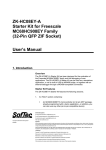
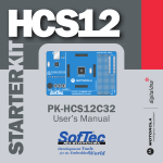
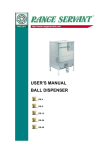
MP8011A
Gang
Programming
System
User’s Manual
Copyright © 2000 SofTec Microsystems®
DC00242
SofTec Microsystems
via Roma, 1
33082 Azzano Decimo (PN) ITALY
Tel: (+39) 0434 640 729
Fax: (+39) 0434 632 695
E-mail (general information): [email protected]
E-mail (marketing department): [email protected]
E-mail (technical support): [email protected]
Web: http://www.softecmicro.com
Warning
SofTec Microsystems only uses programming algorithms provided by the specific device manufacturers.
While every effort has been made to ensure that programming algorithms are correct, all said algorithms are
not guaranteed by the device manufacturer and therefore cannot be guaranteed by SofTec Microsystems.
Users are advised to ensure that devices work correctly in circuit before programming large quantities.
Important
SofTec Microsystems reserves the right to make improvements to the MP8011A programmer, its
documentation and software routines, without notice. Information in this manual is intended to be accurate
and reliable. However, SofTec Microsystems assumes no responsibility for its use; nor for any infringements
of rights of third parties which may result from its use.
SOFTEC MICROSYSTEMS WILL NOT BE LIABLE FOR DAMAGES RESULTING FROM LOSS OF DATA,
PROFITS, USE OF PRODUCTS, OR INCIDENTAL OR CONSEQUENTIAL DAMAGES, EVEN IF ADVISED
OF THE POSSIBILITY THEREOF.
Notice of Conformity
This product is in conformity with the EN-55022, EN-50082-1, ENV-50140 specifications and therefore it
complies with the EMC Directive 89/336/EEC.
Trademarks
Product and company names listed are trademarks or trade names of their respective companies.
Contents
1. GENERAL INFORMATION .......................................................7
INTRODUCTION ................................................................................................ 7
MP8011A MAIN FEATURES ............................................................................. 7
SYSTEM REQUIREMENTS ..................................................................................8
PACKAGE CHECKLIST .......................................................................................8
ELECTRICAL AND PHYSICAL SPECIFICATIONS ...................................................9
SOFTWARE UPGRADES .....................................................................................9
2. GETTING STARTED ............................................................... 11
PROGRAMMER OVERVIEW ...............................................................................11
PROGRAMMING HEADS .................................................................................. 12
INSTALLING THE MP8011A USER INTERFACE ............................................... 12
CONNECTING THE PROGRAMMER TO THE PC ................................................ 13
USER INTERFACE OVERVIEW.......................................................................... 14
The Code Memory Window..................................................................... 15
The Data Memory Window..................................................................... 16
The Info Panel .......................................................................................... 16
The Toolbar .............................................................................................. 17
The Status Bar.......................................................................................... 18
Shortcut Keys ........................................................................................... 18
3. PROGRAMMING.................................................................... 21
PROGRAMMING OVERVIEW ............................................................................ 21
SETTING UP THE PROGRAMMER .................................................................... 21
Selecting The Device To Be Programmed .............................................. 21
Inserting Programming Heads Into Programming Sites ....................23
Placing Devices Into Sockets...................................................................23
Site Selection ............................................................................................23
CODE MEMORY, DATA MEMORY AND OPTION BYTES BUFFERS HANDLING ....24
Buffers Overview .....................................................................................24
Loading Buffer Contents From File........................................................25
Reading Buffer Contents From A Master Device ..................................26
Buffer Editing...........................................................................................27
OPERATIONS ..................................................................................................28
Device Range And Buffer Range ............................................................29
Blank Checking ........................................................................................29
Reading.....................................................................................................29
Erasing .................................................................................................... 30
Programming.......................................................................................... 30
Verifying .................................................................................................. 30
Auto.......................................................................................................... 30
STATISTICS .....................................................................................................30
USING PROJECTS............................................................................................ 31
What Is A Project? ................................................................................... 31
Creating And Editing A Project .............................................................. 31
Loading A Project ....................................................................................32
4. PROTECTED MODE ...............................................................33
OVERVIEW .....................................................................................................33
ENTERING AND EXITING THE PROTECTED MODE ..........................................33
PROTECTED MODE OPERATIONS ....................................................................34
5. TROUBLESHOOTING ............................................................37
INSTALLATION ISSUES .................................................................................... 37
Installing The MP8011A User Interface Under Windows NT ..............37
Parallel Port Topics .................................................................................37
DIAGNOSTIC TEST .......................................................................................... 37
ERROR MESSAGES ..........................................................................................38
GETTING TECHNICAL SUPPORT ......................................................................38
APPENDIX: FILE FORMAT SPECIFICATIONS ..........................39
MOTOROLA S-RECORD FORMAT.....................................................................39
INTEL-HEX FORMAT ......................................................................................40
GLOSSARY ................................................................................ 41
Figures And Tables
The MP8011A Package......................................................................................9
MP8011A Base Unit .........................................................................................11
A Typical Programming Head ........................................................................ 12
Base Unit’s Rear Panel.................................................................................... 14
The MP8011A User Interface ......................................................................... 15
The Code Memory Window ............................................................................ 16
The Info Panel ................................................................................................. 17
The Toolbar ..................................................................................................... 17
Toolbar Buttons............................................................................................... 18
The Status Bar ................................................................................................. 18
Shortcut Keys .................................................................................................. 19
The Select Device Dialog Box .........................................................................22
The Site Selection Dialog Box.........................................................................24
Buffers And Device Memory Zones................................................................25
The Load Code Buffer Dialog Box ..................................................................25
Relations Between Input File And Destination Buffer .................................26
The Option Bytes Dialog Box..........................................................................27
The Auto Dialog Box ...................................................................................... 28
The Project Properties Dialog Box ................................................................. 31
The Protected Mode Dialog Box.....................................................................33
The Protected Mode Main Screen ..................................................................34
The Diagnostic Test Dialog Box .................................................................... 38
Fields in a Motorola S-Record record ............................................................39
Description of the fields of a Motorola S-Record record ..............................39
Fields in an Intel-Hex record ........................................................................ 40
Description of the fields of a Intel-Hex record ............................................. 40
1. General Information
Introduction
The MP8011A Gang Programming System, in combination with a standard
personal computer, is a full featured, high-performance, multiple (gang)
programming system specific for EPROM-, EEPROM- and FLASH-based
microcontrollers. MP8011A supports the concurrent programming of up to
eight devices; different device packages can be accommodated through DIP,
SDIP, SOIC, PLCC and QFP adapters.
MP8011A is a PC-hosted programmer: it communicates with a Windows
95/98/2000/NT user interface through the LPT parallel port. The
MP8011A hardware has two separate sections: a single, universal and
upgradable base unit, ready to support current and future devices, and a
number of device-specific programming heads. Blank checking, reading,
erasing, programming and verifying operations are supported.
MP8011A is ready to support future devices. The upgrade operation for the
support of new devices is as simple as downloading new releases of the PC
software, always available from SofTec Microsystems web site, and
eventually changing the device-specific programming heads. The modular
approach (a general-purpose base unit and dedicated programming heads)
represents the best tradeoff between cost and reliability, since it allows
users to replace damaged heads at a minimum cost. MP8011A can be
operated with a single push-button, the PC being only used to preset
essential parameters like device, input file, device options.
SofTec Microsystems MP8011A standard delivery package consists in the
main gang programmer unit, external power supply adapter, parallel cable
and user's guide. Programming heads can be chosen among the many
possible packages to fit user's requirements.
MP8011A Main Features
§
§
§
§
Gang Programming System Specific For EPROM-, EEPROM- And
FLASH-Based Microcontrollers
Single, Universal And Upgradable Base Unit
Device-Specific Programming Heads
Up To Eight Devices Programmable At Once
MP8011A Gang Programming System
7
§
§
§
Blank Checking, Reading, Erasing, Programming And Verifying
Operations
Windows 95/98/2000/NT User Interface
Parallel Port Connection
System Requirements
The MP8011A Gang Programmer is controlled by a PC user interface
running under Windows.
The following hardware and software is required to run the MP8011A user
interface.
§ An Intel Pentium 90 or better processor running Windows 95,
Windows 98, Windows 2000 or Windows NT version 4.0 or later.
§ 16 MB of random-access memory (RAM) plus 20 MB of available disk
space.
Package Checklist
The MP8011A Programming System package consists of the following
items:
§
The MP8011A Base Unit
§
AC/DC Switching Power Adapter
§
The TP8011A Test Head
§
A parallel cable
§
MP8011A User Interface Software
§
This manual
8
MP8011A Gang Programming System
User’s Manual
Parallel Cable
User Interface Software
AC/DC Switching Power Adapter
TP8011A Test Head
Programmer’s Base Unit
The MP8011A Package
Electrical And Physical Specifications
Operating Voltage
Power Consumption
Dimensions
Weight
Temperature Range
18V DC
600 mA
250 x 38 x 205 mm
1550 g (without Programming Heads)
0 - 40 °C
Software Upgrades
SofTec Microsystems is continuously adding the support for new devices to
the MP8011A Gang Programming System. The support for a new device
consists typically in the development of a specific programming head and in
the release of a new version of the MP8011A user interface. The latest
version of the user interface is always available for free at our download
page on the web: http://www.softecmicro.com/download.html.
MP8011A Gang Programming System
9
2. Getting Started
Programmer Overview
The MP8011A Gang Programming System allows you to program up to
eight devices at once; different device packages can be accommodated
through the appropriate programming heads.
The MP8011A Base Unit is the main programmer unit. The base unit
contains the eight programming sites on which programming heads are
placed during device programming. The base unit is connected to the host
PC through a parallel interface and contains all the logic needed to correctly
drive the I/O lines belonging to each programming site. The base unit
features a “Start” button, which allows you to begin an operation of blank
check, erase, read, program, verify or “auto” (described in the section
“Programming”).
Power LED
“Busy” LED
Programming Head Connector
START Push Button
MP8011A Base Unit
MP8011A Gang Programming System
11
Programming Heads
Programming heads are small printed circuit boards which connect to the
programming sites on the base unit. Each programming head includes the
appropriate socket (DIP, SDIP, SOIC, PLCC or QFP)—and the appropriate
electrical connections—for programming a specific device. When selecting
the device to be programmed, the MP8011A user interface tells you the code
of the programming head required in order to program that device.
Each programming head includes a “Good” LED which, at the end of an
operation on the device, turns on indicating the operation has been
successful. In case of error, the user interface displays the cause of the
problem as long as an hint on how to solve it.
ZIF Socket
Printed Cricuit Boad
“GOOD” LED
Programming Head Code
A Typical Programming Head
Installing The MP8011A User Interface
The MP8011A user interface can be installed by simply running the
Setup.exe file provided on the floppy disks. The setup program will copy the
required files to your hard drive. Additionally, an uninstall program will be
12
MP8011A Gang Programming System
copied, giving you the possibility to uninstall the MP8011A user interface at
any later time.
To install the MP8011A user interface:
1. Insert the installation floppy disk one into your computer’s floppy disk
drive.
2. From Windows, choose Start > Run. Click Browse and choose the
Setup.exe file on the MP8011A floppy disk. Click OK in the Run dialog
box to begin the installation.
3. Note: if you are installing the MP8011A user interface from Windows
NT, you must have logged in as Administrator.
4. Follow the on-screen instructions.
Connecting The Programmer To The PC
To connect the programmer to the PC, follow the steps indicated below:
1. Turn off the PC.
2. Insert the male D-Sub miniature connector of the parallel cable into a
free PC parallel interface.
Note: to make sure that the fastest communication speed between the
programmer base unit and the PC is achieved, reboot your PC, enter
the BIOS utility and make sure that the parallel mode is set to either
EPP or ECP. If your parallel port hardware doesn’t work with the
MP8011A Gang Programmer System (or if it only works in the slow,
standard parallel mode) you might want to consider to purchase the
237-00139 ISA Bus Bidirectional Parallel Port item.
3. Insert the female D-Sub miniature connector of the parallel cable into
the programmer parallel connector (located on the programmer’s rear
panel).
4. Turn the power switch on the “OFF” position. Connect the output
voltage of the AC/DC switching power adapter to the power connector
on the programmer box (located on the programmer’s rear panel). Turn
the power switch on the “ON” position.
5. Turn on the PC and run the MP8011A user interface.
The following figure illustrates where the programmer’s connectors are
located.
MP8011A Gang Programming System
13
R
Power Switch
Power Connector
Parallel Connector
Base Unit’s Rear Panel
User Interface Overview
The MP8011A user interface consists of several elements, organized in a
way that gives you the maximum benefits both in easy-to-use and
productivity terms.
§ A menu bar. The menu bar groups all of the user interface
commands.
§ A toolbar. The toolbar shows the most frequently used commands—
it’s a subset of the menu bar commands.
§ A status bar. The status bar shows the programmer’s status
information, such as information about the device to be programmed,
the programming head required, etc.
§ An Info panel. The Info panel displays information about the device
to be programmed. Additionally, the status of the programming sites is
shown together with the statistics about programmed devices.
§ A Code Memory window. The Code Memory window displays the
content of the current code memory buffer. The content of the code
memory buffer can be edited, loaded from and saved to a file.
§ A Data Memory window. The Data Memory window displays the
content of the current data memory buffer. The content of the data
memory buffer can be edited, loaded from and saved to a file.
The toolbar, the status bar, the Info panel, the Code Memory window and
the Data Memory window can be turned on or off. The Code Memory
window and the Data Memory window, additionally, can be arranged any
way you like. The following figure illustrates the MP8011A user interface.
14
MP8011A Gang Programming System
Menu Bar
Toolbar
Code Memory
Window
Info Panel
Data Memory
Window
Status Bar
The MP8011A User Interface
The Code Memory Window
The Code Memory window displays the content of the current code memory
buffer. The code memory buffer is an intermediate memory (located on the
PC’s RAM) used to prepare the data to program to or to store the data read
from the device’s code memory area. To open the Code Memory window,
choose Window > Code Memory from the menu bar or click the “Code
Memory” button on the toolbar (the Code Memory window command is
only available if a device is selected).
The Code Memory window shows all of the memory locations belonging to
the device’s code memory and their content is displayed both in
hexadecimal and in ASCII format. To edit a single byte, just click on it and
type in the new value.
The Code Memory window also shows additional information, such as the
code memory buffer range and reserved code memory locations.
The Code memory buffer range is the actual portion of the code memory
buffer which is written to or read from the device(s). By default, the code
memory buffer range correspond to the device’s code memory range.
However, you can narrow this range by selecting the start and end address
for the code memory buffer. All read and write operations involving the
code memory are performed only on the range of memory bytes included
on the code memory buffer range. On the Code Memory window, the
content of memory locations outside the code buffer range is shown against
a grey background.
MP8011A Gang Programming System
15
Reserved code memory locations are rendered as “XX”. They cannot be
edited.
Locations
Outside
Code Memory
Buffer Range
ASCII Dump
Hexadecimal
Dump
Reserved
Locations
The Code Memory Window
The Data Memory Window
The Data Memory window displays the content of the current data memory
buffer (if the selected device features a data memory area). The data
memory buffer is an intermediate memory (located on the PC’s RAM) used
to prepare the data to program to or to store the data read from the device’s
data memory area. To open the Data Memory window, choose Window >
Data Memory from the menu bar or click the “Data Memory” button on
the toolbar (the Data Memory window command is only available if the
selected device features a data memory area).
Likewise the Code Memory window, the Data Memory window shows all of
the memory locations belonging to the device’s data memory and their
content is displayed both in hexadecimal and in ASCII format. To edit a
single byte, just click on it and type in the new value.
The Info Panel
The Info panel is placed at the rightmost side of the programmer’s user
interface main window. The Info panel displays information about the
device to be programmed (its package and the required programming
head), the device’s code memory range (as long as the buffer range), the
data memory range (if the selected device features a data memory zone)
and option bytes (if present). Additionally, the status of the programming
sites is shown together with the statistics about programmed pieces.
16
MP8011A Gang Programming System
Device Summary
(Manufacturer, Device Code,
Package, Programming Head
Code)
Code Memory Summary
(Device Range, Buffer Range,
Checksum)
Data Memory Range
Option Bytes Settings
Programming Site Status
(The site in bold is the master site)
Programmed Device Statistics
The Info Panel
The Toolbar
The toolbar shows the most frequently used commands—it’s a subset of the
menu bar commands.
The Toolbar
MP8011A Gang Programming System
17
Opens an existing Project
Loads the contents of a device into
buffers
Saves the current Project
Writes the buffers content to the
devices
Edits Project properties
Verifies that the devices content
matches the buffers content
Selects a new device to be
programmed
Performs various operations at once
Edits option bytes
Shows or hide the Code Memory
window
Blank checks the devices content
Shows or hide the Data Memory
window
Erases the devices content
Recalls the online help
Toolbar Buttons
The Status Bar
The status bar shows the programmer’s status information, such as
information about the device to be programmed, the programming head
required, etc. The various fields of the status bar are illustrated below.
Menu Command Description
Programming Head Code
Device Summary
(Manufacturer, Device Code, Package)
Device Info
The Status Bar
Shortcut Keys
Some of the MP8011A user interface commands are quickly accessible via
keystrokes. The following table summarizes the available shortcut keys.
18
MP8011A Gang Programming System
Command
Goto Address
Find
Edit Option Bytes
Select Device
Blank Check
Read
Erase
Program
Verify
Auto
Site Selection
Shortcut Key
Ctrl + G
Ctrl + F
Ctrl + O
Ctrl + D
Ctrl + B
Ctrl + R
Ctrl + E
Ctrl + P
Ctrl + V
Ctrl + A
Ctrl + S
Shortcut Keys
MP8011A Gang Programming System
19
3. Programming
Programming Overview
Programming is the procedure consisting in writing the contents of the
buffers to one or more device. Buffers are intermediate memories (located
on the PC’s RAM) for the temporary storage of information during
programming sessions. Buffers contain the data to be programmed to and
read from the selected device. The MP8011A user interface handles three
types of buffer: the code memory buffer, the data memory buffer and the
option bytes buffer. All these buffers can be edited; the code memory and
data memory buffer can be additionally saved to and read from files.
A typical programming session involves the following steps:
1. Setting up the programmer (device selection, insertion of the
appropriate programming heads, insertion of the devices into
programming head socket, site selection);
2. Buffers editing (code memory buffer editing, data memory buffer
editing, option bytes editing);
3. Programming.
The steps 1 and 2 can be automated by using Projects (see the chapter
“Using Projects”, later in this section).
Setting Up The Programmer
Before to start a programming session, there are a number of steps to be
followed in order to make sure the MP8011A system works properly. They
are:
1. Selection of the device to be programmed;
2. Insertion of the appropriate programming heads;
3. Insertion of the devices to be programmed into the programming head
sockets;
4. Site selection.
Selecting The Device To Be Programmed
When writing to or reading data from a device, the MP8011A Gang
Programming System uses a specific reading/writing algorithm targeted to
MP8011A Gang Programming System
21
that specific device. Additionally, for the algorithm to be properly
performed, a programming head specific for that device is also required. A
programming head includes the appropriate socket and the appropriate
electrical connections for programming a specific device. When selecting
the device to be programmed, the MP8011A user interface tells you the code
of the programming head required in order to program that device.
To select the device you are working with, select Operations > Select
Device, or just click the “Select Device” button on the toolbar. The
following dialog box will appear.
The Select Device Dialog Box
On the hierarchical tree on the left, choose the manufacturer and the device
family of the device you are going to program. On the right pane, a list of all
the devices belonging to the selected device family appears, together with
additional information about their package and the programming head
required to program them. Choose the device code you are working with
and click “OK”.
The information summary about the selected device will be shown in the
Info panel. The details of the code memory buffer, data memory buffer and
option bytes will reflect those of the selected device. Additionally, the
MP8011A user interface will use the device-specific read/write algorithms
when performing reading/writing operations from/to the device.
22
MP8011A Gang Programming System
Inserting Programming Heads Into Programming Sites
After choosing the device you are working with, you have to use the
appropriate programming head in order to read data from or write data to
the physical devices. A read operation can be performed from only one
programming site per time; write operations can be performed to as many
as eight programming sites per time.
Accordingly, insert one or more programming heads in the programming
sites. The programming heads need not to occupy consecutive
programming sites; the programming sites to use during reading/writing
operations can be specified later.
Note: when inserting or removing programming heads, make
sure the programmer base unit is OFF.
Placing Devices Into Sockets
After the programming heads are in place, you can proceed inserting the
devices into the programming heads’ sockets. When inserting devices, make
sure you are placing them correctly. Refer to the figure depicted on the
programming heads for how to correctly align devices into sockets.
Site Selection
Depending in which programming site you placed the programming heads,
you need to tell the MP8011A user interface which programming sites to
use during reading/writing operations. This can be done via the Site
Selection dialog box (Settings > Site Selection).
MP8011A Gang Programming System
23
The Site Selection Dialog Box
To select which programming sites to use, just check the check boxes
corresponding to those programming sites. Icons will indicate whether
appropriate programming heads (according to the previously selected
device) are inserted into the selected programming sites.
Additionally, the Site Selection dialog box allows you to define the which of
the eight programming sites acts as the master site. The master site is the
programming site used during read operations. When reading a device
content, you must place the device on the programmer’s master site.
Code Memory, Data Memory And Option Bytes Buffers
Handling
Buffers Overview
Buffers are intermediate memories (located on the PC’s RAM) for the
temporary storage of information during programming sessions. Buffers
contain the data to be programmed to and read from the selected device.
The MP8011A user interface handles three types of buffer: the code
memory buffer, the data memory buffer and the option bytes buffer. All
these buffers can be edited; the code memory and data memory buffer can
be additionally saved to and read from files. The following figure illustrates
the relationships between buffers and device memory zones.
24
MP8011A Gang Programming System
PC
Device
Code
Memory
Buffer
Code
Memory
Data
Memory
Buffer
Data
Memory
Option Bytes Buffer
Option Bytes
Buffers And Device Memory Zones
Loading Buffer Contents From File
The content of the code memory buffer and the content of the data memory
buffer can be loaded from an external file. This can be done via the File >
Load > Code Buffer and File > Load > Data Buffer commands. The
following dialog box will appear when loading a file into the code memory
buffer.
The Load Code Buffer Dialog Box
MP8011A Gang Programming System
25
The file name is the name of the file to load. Click the “...” button to browse
through directories. The file format defines how the user interface
interprets data when loading a file into the code or data buffer. Available
file formats are binary, Intel-Hex and Motorola S-Record. You can
additionally specify a file offset, that is the initial position (in bytes, starting
from the beginning of the file contents) from where data will be loaded. The
file offset allows you to discard a first portion of the input file.
You can also decide where, in the destination buffer, data will be placed. By
default, the MP8011A user interface will load data into the buffer starting
from the first available location of the target buffer (the first location of the
code memory range or data memory range, based on the memory zones of
the selected device).
Additionally, if the source file is in Intel-Hex or Motorola S-Record format,
you can decide how to fill the buffer locations not covered by the load
process. Options are “00h”, “FFh”, “Don’t Care”.
INPUT FILE
DESTINATION BUFFER
Start Address
File Offset
Unused Locations
Are Filled With 00h,
FFh Or Left
Untouched
Portion Of The Input
File That Is Copied To
The Destination Buffer
Relations Between Input File And Destination Buffer
Reading Buffer Contents From A Master Device
Buffer contents (code memory buffer, data memory buffer and option
bytes) can also be read from a master device. See “Operations/Reading”
later in this section.
26
MP8011A Gang Programming System
Buffer Editing
To edit the contents of both the code memory buffer and the data memory
buffer, just open the respective window, click on a byte to edit and type in
the new value. Additionally, some basic editing commands are available to
help you in the editing process. They are placed under the “Edit” menu, and
their scope is either the Code Memory window or the Data Memory
window, whichever is the active window.
The Fill command fills a range of memory locations with a fixed byte.
The Goto Address command allows you to jump precisely to a given
memory location.
The Find command looks for a specific pattern of bytes.
The editing of the option bytes is done via the Option Bytes dialog box
(Edit > Option Bytes).
The Option Bytes Dialog Box
The Option Bytes dialog box is specific for each device. The Option Bytes
dialog box allows you to edit each single bit (exception made for reserved
bits) of the option bytes of the device you are working with. By clicking the
“Details” button you can access further information on the meaning of each
of the option bits.
MP8011A Gang Programming System
27
Operations
The term “operations” refers to the set of actions that it is possible to
perform on devices. This set includes blank checking, erasing, reading,
programming and verifying. A special operation, the Auto operation,
groups the blank checking, erasing, programming and verifying operations
in a single operation, speeding up the programming process.
All of the operations share the same dialog box, with minor differences.
The Auto Dialog Box
The figure above shows the Auto dialog box, but the dialog boxes for blank
checking, erasing, reading, programming and verifying share the same
layout.
The “Steps” section groups the operation that are going to be performed on
the enabled programming sites. Depending on the specific operation and on
the selected device, the “Steps” section shows all of the available options,
which are (by default) all checked. You may deselect the steps you don’t
wish to perform.
The “Operation Status” section shows the programming sites status, as long
as any error that may occur during the operations, in a graphical way.
Detailed information for each of the programming sites are displayed on
the “Messages” section.
The “Start” button begins the execution of the checked steps. When an
operation dialog box is open, pressing the “Start” push button on the
28
MP8011A Gang Programming System
programmer’s base unit has the same effect of clicking the “Start” button on
the dialog box.
On the bottom of the dialog box, a progress bar shows the execution status
of each step.
Note: when you are performing an operation, the “Busy” LED
on the programmer’s base unit turns on. When the LED is on,
removing the devices from the sockets or removing the
programming heads from the programming sites will result in
an unsuccessful operation and MAY CAUSE DAMAGE TO BOTH
THE DEVICES AND THE PROGRAMMER.
Device Range And Buffer Range
Some operations act on the code memory: they transfer data from the code
memory buffer to the device’s code memory or vice versa. In these cases,
what is actually used is the portion of code memory buffer included in the
code memory buffer range.
The code memory buffer range is the actual portion of the code memory
buffer which is written to or read from the device(s). By default, the code
memory buffer range correspond to the device’s code memory range.
However, you can narrow this range by selecting the start and end address
for the code memory buffer. All read and write operations involving the
code memory are performed only on the range of memory bytes included
on the code memory buffer range. On the Code Memory window, the
content of memory locations outside the code buffer range is shown against
a grey background.
Blank Checking
The blank check is a test performed on the device’s code memory, data
memory or option bytes (or all of them) in order to establish if that portion
of the device is blank. The zones of the device’s memory that can be read
(and therefore blank checked) depend on the selected device. To perform a
blank check, select Operations > Blank Check.
Reading
A reading operation is used to transfer the content of the device’s code
memory, data memory or option bytes (or all of them) into the relative
buffer(s). The zones of the device’s memory that can be read depend on the
selected device. When reading a device content, you must place the device
on the programmer’s master site (to define the master site, use the Site
Selection command under the Settings menu). To perform a reading
operation, select Operations > Read.
MP8011A Gang Programming System
29
Erasing
An erasing operation allows you to erase the contents of the device’s code
memory, data memory or option bytes (or all of them). The zones of the
device’s memory that can be erased depend on the selected device. To
perform an erasing operation, select Operations > Erase.
Programming
A programming operation writes the content of the code memory buffer,
data memory buffer or option bytes (or all of them) into the corresponding
memory zones of the device(s) you are working with. The zones of the
device’s memory that can be written depend on the selected device. To
perform a programming operation, select Operations > Program.
Verifying
The verifying operation is used to compare the contents of the device’s code
memory, data memory or option bytes (or all of them) with those of the
corresponding buffers on the user interface. The zones of the device’s
memory that can be read (and therefore compared against the buffers’
contents) depend on the selected device. To perform a verifying operation,
select Operations > Verify.
Auto
The Auto operation groups the blank checking, erasing, programming and
verifying operations in a single operation, speeding up the programming
process. To perform an Auto operation, select Operations > Auto.
Statistics
The “Statistics” section on the Info panel shows the total number of
programmed devices, the number of successfully programmed devices and
the devices that cannot be programmed correctly. The statistics are updated
each time a device is programmed (either via the programming operations
or the Auto operation). Statistics are reset each time you launch the
MP8011A user interface, or by selecting the Reset Statistics command
under the Operations menu.
30
MP8011A Gang Programming System
Using Projects
What Is A Project?
A Project is a MP8011A file which groups all the information you need to
program a particular device: the device code, a link to the code memory and
data memory buffer files, option byte settings, etc. Working with Projects
allows you to quickly and safely maintain programming data between
programming sessions.
Additionally, Project files allows you to work in Protected Mode (for more
information, see the section “Protected Mode”).
Creating And Editing A Project
To create a new Project select the New command from the Project menu.
You will be requested to give the Project file a name and a path; then the
Project Properties dialog box will appear.
The Project Properties Dialog Box
The Project Properties dialog box allows you to set up all of the relevant
information about a programming session. The same dialog box can be
recalled at any time (by selecting Project > Project Properties) and the
information contained in it can be edited as well.
MP8011A Gang Programming System
31
The Project Properties dialog box groups information about the code of the
device you are working with, the code memory buffer file to use, the data
memory buffer file to use (if the selected device features a data memory
area), the code memory buffer range and the option bytes settings.
Note: you can change all of these settings both via the Project Properties
dialog box and via the specific user interface commands Select Device
and Code Buffer Range (under the Operation menu), Option Bytes
(under the Edit menu) and Load > Code Buffer and Load > Data
Buffer (under the File menu). If a Project is open, these single commands
will automatically update the Project settings.
Every time you modify one or more Project settings, remember to select
Project > Save to store them on the Project file.
Loading A Project
The list of the most recently used Projects appears at the bottom of the
Project menu. Simply select one of these Projects to open it. If a Project
you want to work with doesn’t appear in the list, select Project > Load
and pick the Project file you wish.
32
MP8011A Gang Programming System
4. Protected Mode
Overview
Protected Mode simplifies the programming process by means of an easy,
guided procedure that requires no special knowledge. Protected Mode is
suitable for the programming of a large amount of devices. Entering and
exiting the Protected Mode is password protected.
When in Protected Mode, it is only possible to program devices by loading
all of the required parameters from a Project file (for more information, see
the chapter “Using Projects” in the previous section). Only Project files
placed under the “Projects” directory (relative to the MP8011A user
interface installation directory) will be available for selection.
The Protected Mode features bigger icons and larger fonts for an easier
feedback during programming sessions.
Entering And Exiting The Protected Mode
To enter the Protected Mode, select Settings > Protected Mode. The
following dialog box will appear.
The Protected Mode Dialog Box
MP8011A Gang Programming System
33
When pressing the “OK” button, the user interface will immediately switch
to the Protected Mode. The required password will be used for switching
back to the standard MP8011A user interface. Additionally, if the MP8011A
user interface is closed from within the Protected Mode, next time you
launch the user interface it will still open in the Protected Mode. The
following figure shows what the Protected Mode looks like (in the Protected
Mode, the user interface occupies the whole screen area and can’t be
resized).
The Protected Mode Main Screen
To exit the Protected Mode, click the “Normal Mode” button and enter the
same password you used to enter the Protected Mode. If you forget the
password, just type in “ADMIN”.
Protected Mode Operations
While in Protected Mode, all you can do is:
§ Program devices by loading all of the required parameters from a
Project file. Only Project files placed under the “Projects” directory
34
MP8011A Gang Programming System
§
(relative to the MP8011A user interface installation directory) will be
available for selection.
If the selected Project file does not contain a code memory buffer file
reference, it will be possible to read the code memory area from
another device, and turning on device protection for the subsequent
programming operations.
MP8011A Gang Programming System
35
5. Troubleshooting
Installation Issues
Installing The MP8011A User Interface Under Windows NT
In order to install the MP8011A under Windows NT, you must have logged
in as Administrator.
Parallel Port Topics
The programmer communicates with the PC trough a standard,
bidirectional parallel port.
The fastest data transfer rates are achieved when the parallel port mode is
set to EPP or ECP. If neither the EPP or ECP mode are supported by your
PC’s parallel port hardware, the MP8011A User Interface will use the
parallel port bidirectional transfer mode. If either this mode is not
supported, the standard (nibble) mode will be used instead. Please note,
however, that the standard mode only achieves much lower transfer rates
than the EPP or ECP modes, thus resulting in slowing down the devices’
programming process.
To make sure that the fastest communication speed between the
programmer base unit and the PC is achieved, reboot your PC, enter the
BIOS utility and make sure that the parallel mode is set to either EPP or
ECP. If your parallel port hardware doesn’t work with the MP8011A Gang
Programmer System (or if it only works in the slow, standard parallel
mode) you might want to consider to purchase the 237-00139 ISA Bus
Bidirectional Parallel Port item.
Diagnostic Test
The programmer includes a diagnostic test to verify that the base unit
hardware works properly. To start the test, choose Operations >
Diagnostic Test from the menu bar. The following dialog box will appear.
MP8011A Gang Programming System
37
The Diagnostic Test Dialog Box
The diagnostic test also performs a foolproof test of all of the I/O lines of a
specific programming site. The diagnostic test will guide you through the
simple steps required to verify both the base unit hardware and a
programming site I/O lines—just follow the instructions that will appear on
the screen.
Error Messages
Most of the MP8011A user interface error messages come together with an
explanation and a suggestion on how to solve the problem. In case you can’t
still solve your problem, please contact our Technical Support.
Getting Technical Support
Technical assistance is provided free to all customers. For technical
assistance, documentation and information about products and services,
please refer to your local SofTec Microsystems partner.
SofTec Microsystems offers its customers a free technical support service at
[email protected].
38
MP8011A Gang Programming System
Appendix: File Format Specifications
Motorola S-Record Format
The Motorola S-Record format encodes programs or data files in an ASCII
format. S-records are character strings of five fields: record type, record
length, memory address, data and checksum. Each byte of binary data is
encoded as a two-character hexadecimal number: the first character
represents the high-order four bits and the second the low-order four bits of
the byte.
TYPE
LENGTH
ADDRESS
DATA
CHECKSUM
Fields in a Motorola S-Record record
Field
TYPE
LENGTH
ADDRESS
DATA
CHECKSUM
Length
(Bytes)
2
2
4, 6 or 8
0-n
2
Description
This field indicates the start of a record and identifies
the record type as follows:
S0 = Header record
S1 = Data record for 16-bit addresses
S2 = Data record for 24-bit addresses
S3 = Data record for 32-bit addresses
S5 = Count record
S7 = Terminator record for 32-bit addresses
S8 = Terminator record for 24-bit addresses
S9 = Terminator record for 26-bit addresses
This field specifies the record length which includes
the address, data and checksum fields. The 8-bit
record length value is converted to two ASCII
characters. The first character represents the most
significant nibble.
This field contains the load address.
This field contains the data bytes.
The last two bytes in the data record contain the
record checksum. The checksum is the sum of the
record length, load address and data fields. This sum
is then complemented (1's complement) and
converted to two ASCII characters.
Description of the fields of a Motorola S-Record record
MP8011A Gang Programming System
39
Intel-Hex Format
The Intel-Hex format encodes programs or data files in an ASCII format.
Intel-Hex records are character strings of six fields: record mark, record
length, memory address, record type, data and checksum. Each byte of
binary data is encoded as a two-character hexadecimal number: the first
character represents the high-order four bits and the second the low-order
four bits of the byte.
:
LENGTH
ADDRESS
TYPE
DATA
CHECKSUM
Fields in an Intel-Hex record
Field
RECORD MARK
Length
(Bytes)
1
LENGTH
2
ADDRESS
TYPE
4
2
DATA
CHECKSUM
0-n
2
Description
This field indicates the start of a record and consists
of an ASCII colon(“:”).
This field indicates the number of data bytes in the
data record.
This field contains the load address.
This field identifies the record type:
00 = data record
01 = end record
02 = extended start record (not supported)
03 = segmented start record (not supported)
This field contains the data bytes.
The last two bytes in the data record contain the
record checksum. The checksum is the sum of the
record length, load address, record type and data
fields. This sum is then complemented (2's
complement), truncated in an 8 bit field and then
converted to two ASCII characters.
Description of the fields of a Intel-Hex record
40
MP8011A Gang Programming System
Glossary
Base unit is the main
programmer unit, which contains
the eight programming sites on
which programming heads are
placed during device
programming. The base unit is
connected to the host PC through a
parallel interface and contains all
the logic needed to correctly drive
the I/O lines belonging to each
programming site.
Blank check is a test performed
on the device’s code memory, data
memory or option bytes (or all of
them) in order to establish if that
portion of the device is blank.
Buffers are intermediate
memories (located on the host PC’s
RAM) for the temporary storage of
information during programming
sessions. Buffers contain the data
to be programmed to and read
from the selected device. The
MP8011A user interface handles
three types of buffer: the code
memory buffer, the data memory
buffer and the option bytes buffer.
All these buffers can be edited; the
code memory and data memory
buffer can be additionally saved to
and read from files.
Checksum is a modular sum of
the digits in a set of data, used to
provide a check of any errors that
may arise in it. The MP8011A user
interface calculates and displays
MP8011A Gang Programming System
the checksum of the portion of the
code memory buffer included in
the code memory buffer range
(that is, the portion of the code
memory buffer that is written to
the device when programming).
Code memory is the portion of
the selected device’s memory
which contains the program to be
executed (it is usually a FLASHlike memory). Code memory can
only be written via a programming
procedure.
Code memory buffer is an
intermediate memory (located on
the host PC’s RAM) used to
prepare the data to program to or
to store the data read from the
device’s code memory area.
Code memory buffer range is
the actual portion of the code
memory buffer which is written to
or read from the device(s). By
default, the code memory buffer
range correspond to the device’s
code memory range. However, you
can narrow this range by selecting
the start and end address for the
code memory buffer. All read and
write operations involving the code
memory are performed only on the
range of memory bytes included on
the code memory buffer range. On
the Code Memory window, the
content of memory locations
outside the code buffer range is
shown against a grey background.
Code Memory window displays
the content of the current code
41
memory buffer. The content of the
code memory buffer can be edited,
loaded from and saved to a file.
Data memory is the portion of
the selected device’s memory
which contains user data (it is
usually an EEPROM-like memory).
Data memory can change during
program execution and can be
initialized in a known state by the
MP8011A user interface. Note: not
all devices include a data memory
area.
Data memory buffer is an
intermediate memory (located on
the host PC’s RAM) used to
prepare the data to program to or
to store the data read from the
device’s data memory area.
Data Memory window displays
the content of the current data
memory buffer. The content of the
data memory buffer can be edited,
loaded from and saved to a file.
Device is the chip to be
programmed. Depending on the
package of the device, you will
need to use the appropriate
programming head (which
includes the appropriate socket) to
accommodate the chip and ensure
proper programming.
File format defines how the
programmer user interface
interprets data when loading a file
into the code or data buffer.
Available file formats are binary,
Intel-Hex and Motorola S-Record.
42
Info panel is placed at the
rightmost side of the programmer’s
user interface main window. The
Info panel displays information
about the device to be programmed
(its package and the required
programming head), the device’s
code memory range (as long as the
buffer range), the data memory
range (if the selected device
features a data memory zone) and
option bytes (if present).
Additionally, the status of the
programming sites is shown
together with the statistics about
programmed pieces.
Master site is the programming
site used during read operations.
When reading a device content,
you must place the device on the
programmer’s master site. The
MP8011A user interface allows you
to define which of the eight
programming site is the master
site.
Option bytes are one or more
bytes that specify low-level options
for the device to be programmed.
The MP8011A user interface allows
you to graphically define the value
of each bit of the option bytes of
the selected device. Option bytes
allows you to specify, for example,
if the device to be programmed
must be readout protected, what
kind of clock generator to use, etc.
Programming is the procedure
consisting in writing the contents
of the buffers to one or more
device.
MP8011A Gang Programming System
Programming heads are small
printed circuit boards which
connect to the programming sites
on the base unit. Each
programming head includes the
socket for programming a specific
device. When selecting the device
to be programmed, the MP8011A
user interface tells you the code of
the programming head required in
order to program that device.
Protected Mode is password
protected.
Sockets are placed on
programming heads and
accommodate the various device
packages.
Programming sites are the
places where programming heads
are connected to the programmer
base unit. There are eight
programming sites on the base
unit, and one up to eight
programming heads can be used
during gang programming. The
MP8011A user interface allows you
to graphically define on which
programming sites programming
heads are connected to.
Project is a MP8011A file which
groups all the information you
need to program a particular
device: the device code, a link to
the code memory and data memory
buffer files, option byte settings,
etc. Working with Projects allows
you to quickly and safely maintain
programming data between
programming sessions.
Protected Mode simplifies the
programming process by means of
an easy, guided procedure that
requires no special knowledge.
Protected Mode is suitable for the
programming of a large amount of
devices. Entering and exiting the
MP8011A Gang Programming System
43