1
Troubleshooting
9161 Ethernet Network Interface Device User’s Manual
Running Diagnostics
x
10G2
PORT
10G1
PORT
Tx
Rx
Rx
Tx
FAULT
NO DATA
x
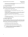
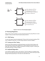
Link loss detected on 10G1 Port
Fault propogated to 10G2 Port
10G2 Port Tx stops transmitting data
10G2 Port Tx LED turns red
10G1 PORT TO 10G2 PORT
10G1
PORT
10G2
PORT
Tx
Rx
Rx
Tx
x
RMTF
Link loss detected on 10G2Port
Fault propogated to 10G1Port
10G1 Port stops transmitting data
10G1 Port LED turns red
10G2 PORT TO 10G1 PORT
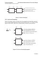
Figure 4-2. Link Loss Forwarding Propagation
4.3 Running Diagnostics
When you set up a new connection, you can verify the link connectivity using PING prior to sending data. A Latency and Jitter Test will verify the quality of the link.
4.3.1 PING Testing
You can verify network connectivity with another IP device within the subnet by sending a PING
to the IP address for that device. For PING testing instructions, reference Chapter 3.
4.3.2 Latency and Jitter Testing
Latency/Jitter Testing measures and reports performance and quality of the link between the
9161 and another Canoga Perkins capable device. Results reported include the Frame Loss
Ratio (FLR), and the minimums, average, and maximums for latency and jitter. For latency and
jitter testing instructions, reference Chapter 3.
4.4 Loopback Diagnostics
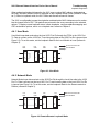
Use Loopbacks to diagnose a fault on the optical link. The 9161 supports two loopback modes
that you can set at the local site for both the local and remote 9161s. These modes loop the data
through either the physical layer on the User side or the Network side.
35