1
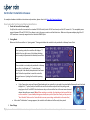
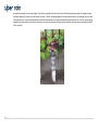
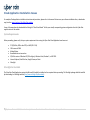
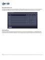
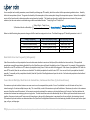
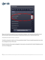
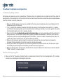
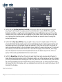
XCI Smart Sprinkler Controller Troubleshooting Guide If you are experiencing difficulties with your Cyber-Rain System, please contact our Technical Support Department: Telephone: (877) 888-1452 ◦ Email: [email protected] Copyright © 2012 Cyber-Rain, Inc. All rights reserved. Table of Contents Introduction ............................................................................................................................................................... 4 Controller Installation Issues..................................................................................................................................... 5 New Controller Not Detected During Installation ................................................................................................................................ 5 Manual Run Function on Controller Does Not Run Zone ...................................................................................................................... 6 Cloud Application Installation Issues ......................................................................................................................... 8 System Requirements .................................................................................................................................................................... 8 Silverlight Not Installed .................................................................................................................................................................. 8 Cloud Application Operation ....................................................................................................................................... 9 Zone Watering Run Times are Too Short or Too Long ......................................................................................................................... 9 Rain Holds Occur too Frequently/Infrequently ................................................................................................................................. 12 Zones Run for Multiple, Short Intervals Instead One, Continuous Run Time (Cycle & Soak Issues) ......................................................... 12 Scheduled Run Ends Before All Zones are Watered .......................................................................................................................... 13 Post Setup Communication ...................................................................................................................................... 14 Controller Offline/Wireless Communication Issues ........................................................................................................................... 14 Gateway Access Point .............................................................................................................................................. 15 Determining if the Gateway is Online ............................................................................................................................................. 15 Gateway Access Point does not Appear in Network Devices Window ................................................................................................... 15 Poor Signal Strength .................................................................................................................................................................... 17 Gateway frequently goes offline .................................................................................................................................................... 18 Power Cycle Gateway ................................................................................................................................................................... 18 Flow Meter Installation and Operation ..................................................................................................................... 19 Troubleshooting Wiring Problems ................................................................................................................................................... 19 Flow Meter Not Registering Flow .................................................................................................................................................... 19 False Underflow/Overflow Alerts on Particular Zone ......................................................................................................................... 20 Flow Alert on Zone 0 .................................................................................................................................................................... 21 Flow Sensor Reports “255 GPM” Flow Rate/“OVER TEMP ALERTS” ...................................................................................................... 22 Rain Sensor Issues................................................................................................................................................... 24 2|Cyber-Rain XCI Smart Irrigation Controller Troubleshooting Guide Rain Sensor Not Stopping Controller after it Rains ........................................................................................................................... 24 Rain Sensor Puts System on Hold after Being Enabled ...................................................................................................................... 24 Logging in the Cloud Application .............................................................................................................................. 26 Launching the Cloud Application .................................................................................................................................................... 26 Unable to login with Username and Password.................................................................................................................................. 26 3|Cyber-Rain XCI Smart Irrigation Controller Troubleshooting Guide Introduction The following document is intended to aid the user in diagnosing and resolving common issues that may occur during the installation and operation of the Cyber-Rain Smart Irrigation Control System. Please keep this manual stored in a convenient location for future use. Please remember that the Frequently Asked Questions section of our website provides answers to the most common queries, and our support team can be contacted via email at [email protected], or by calling Customer Support toll free at (877) 888-1452 x3 Monday through Friday, 9AM to 5PM Pacific Time. 4|Cyber-Rain XCI Smart Irrigation Controller Troubleshooting Guide Controller Installation Issues For complete hardware installation instructions and procedures, please refer to the Cyber-Rain Download Section. New Controller Not Detected During Installation 1. Check the Controller’s Power Supply Verify that the controller is connected to a standard 120 VAC outlet (via the 24 VAC transformer) and the LCD screen is lit. The acceptable power range is between 105 and 129 VAC. If the voltage is not in this range, contact a certified electrician. Make sure the power adapter plug of the 24 VAC transformer is securely snapped into the controller POWER input. 2. Pairing Mode Make sure that the controller is in “pairing mode”. Pairing mode allows the controller to be paired with a Gateway Access Point: When in pairing mode, the controller will display a “>” symbol in the top right corner of its display indicating that it is ready to be paired with a Gateway Access Point. If the controller is not ready to be paired with a Gateway Access Point, it will display an “|” symbol instead, indicating that it has already been paired with an Access Point. Follow the steps below to reset the controller, otherwise known as “putting the Controller in pairing mode.” I http://www.cyber-rain.com/Support/Downloads.aspxf your controller is not ready to be paired with a Gateway Access Point (and displays the “|” symbol) and you would like to reset the controller and put it back into pairing mode, simply press the UP and RIGHT directional arrows keys on the controller face at the exact same time and release them after one second. (Note: When resetting a controller, all schedules and settings will be lost on the controller. If your schedule/settings are already set up in the Cyber-Rain Cloud, you can press the “Save Schedule” button on the Controller tab to resave your settings and schedule to the controller.) After a brief “Initialization” message appears, the controller will reboot and will be ready to be paired. 3. Out of Range 5|Cyber-Rain XCI Smart Irrigation Controller Troubleshooting Guide If the controller is in pairing mode, but it is still not being detected, the controller may be out of range of the Gateway Access Point that is connected to the modem/router. Make sure there are no metal objects surrounding either the controller or the Gateway Access Point. Bring the controller as close as possible to the Gateway Access Point and retry finding the controller by clicking “Search Again”. If the controller is found when it is closer to the Gateway access point, then there is a signal range issue. See the Poor Signal Strength section of this Troubleshooting Guide for tips on increasing signal strength. If none of these work, contact Cyber-Rain Technical Support for assistance. 4. Hardware malfunction If the controller is in pairing mode but is not found when it is brought next to the Gateway Access Point, there may be a problem with the controller or the Gateway Access Point. Contact Cyber-Rain Technical Support for assistance. Manual Run Function on Controller Does Not Run Zone To manually run a zone directly from the controller, use the LEFT or RIGHT arrows on the controller to select which zone you would like to run. Next, press the SELECT button on the controller to run the zone. The UP and DOWN buttons on the controller are used to change the duration of the run. If some or all zones do not run, it could be due to the following. Valve Wires and/or Wire Harness Not Correctly Installed. This is often the issue if a single zone or group of zones is not working. Make sure the common wire (usually white) is securely fastened to the left-most opening on the harness. Next, the zone wires (usually color coded) should be securely fastened in the next 8 slots, and the last opening on the 10 pin wire harness should contain the master valve wire (if your system has a master valve). Every wire should have about a ¼” of the insulation stripped at the end of the wire to provide good contact with the harness. Lightly tug on each of the wires to make sure they are secure. Lightly tug on the wire harness to make sure it is locked in place. If it will not lock, contact Cyber-Rain Technical Support. Retry the manual run. Common or Valve Wires Are Not Functioning. Unplug the wire harness and use an ohm meter to check the resistance between the common wire and each of the valve wires. Normal resistance readings will be between 20 and 60 ohms. An open circuit will read infinite or very high (>100K ohms) resistance, while a short circuit will read very low resistance (less than 20 ohm). A partial connection will read somewhere between 60 and 80 ohms. Running more than one valve in series on same zone will lower the resistance significantly, and increase the electrical load on the circuit. Make sure the resistance does not go below 20 ohms. Finally, the controller uses a “hot common”, so the valve common must not be grounded. Valves Not Functioning. Make sure that the valve has water supplied to it. Then manually “bleed” (open) the valve and make sure water flows. This is usually done by turning a small knob on the top of the valve (see picture below). Verify that water does flow when the valve is opened. If it does not, there may be a problem in your irrigation system, or the valve may be faulty. Close the valve. If manually running the valve worked 6|Cyber-Rain XCI Smart Irrigation Controller Troubleshooting Guide as expected, manually run the zone using the Cyber-Rain controller for at least two minutes. When functioning normally, the irrigation system should be supplying 24 volts to the valve while it is active. If 24 volts are being supplied to the valve and the valve is not opening, then the valve is likely defective. If a valve is determined to be defective either replace it or contact a landscape professional to do so. If 24 volts are not being supplied to the valve check to ensure the valve wire is correctly connected to the valve harness, and that the valve harness is properly installed in the controller. 7|Cyber-Rain XCI Smart Irrigation Controller Troubleshooting Guide Cloud Application Installation Issues For complete Cloud application installation instructions and procedures, please refer to the manual that came on your software installation disc, or download a copy from the support section of the Cyber-Rain website. A copy of the manual can be downloaded be clicking the “Cloud User Manual” link for your visually corresponding system configuration from the Cyber-Rain support section of the website. System Requirements Before proceeding, please verify that your system requirements for running the Cyber-Rain Cloud Application have been met: PC (32/64-bit, AMD or Intel CPU) or MAC (OS X 10.6) 1GB or more of RAM Modem/Router Broadband internet connection 32/64-bit version of Windows XP (SP3 or higher), Windows Vista, Windows 7, or MAC OSX. Internet Explorer, Mozilla Firefox, Google Chrome, or Safari Silverlight Silverlight Not Installed The Cyber-Rain Cloud Application requires that Microsoft Silverlight be installed on the computer before proceeding. The Silverlight package should be installed by downloading it at Silverlight website (http://www.siverlight.net/downloads). 8|Cyber-Rain XCI Smart Irrigation Controller Troubleshooting Guide Cloud Application Operation Zone Watering Run Times are Too Short or Too Long Use the Cyber-Rain Software to Automatically Determine Watering Times The Cyber-Rain Cloud Irrigation System is designed to adjust zone watering times depending on the local weather. Weather information is downloaded from the internet periodically. The Cyber-Rain Cloud Application can determine ideal watering times based on user defined presets. To set your recommended schedule, log onto the CyberRain Cloud Application and navigate to the zone tab (see picture below). For each zone, enter the following zone details: plant type, sprinkler type, sun exposure, slope type, and soil type. Leave the “Maximum Cycle (minutes)” and “Soak Time (minutes)” fields blank. Click the “Adjust My Schedule Based on These” button, and the Cyber-Rain algorithm will determine your watering schedule. This schedule indicates the maximum watering times for the hottest/driest day of the year. The Cyber-Rain system uses the weather conditions to determine the amount of time to water your zones—the watering time will be equal to or less than the time listed on the watering schedule. 9|Cyber-Rain XCI Smart Irrigation Controller Troubleshooting Guide Manually Adjust Zone Watering Times The Cyber-Rain Cloud Application allows users to manually adjust their watering schedules to water each zone for more or less time. Log into the Cyber-Rain Cloud Application and navigate to the controller tab. Adjust the number of minutes in the schedule matrix (pictured below), and click “save schedule.” Adjust Advanced Settings The adjusting the advanced settings will alter the parameter used to determine run times for all zones associated with a site. The Advance Settings table is located in the “Site” tab of the Cyber-Rain Cloud Application. Users can change the parameters by typing in the appropriate field and clicking Load Forecast. 10 | C y b e r - R a i n X C I S m a r t I r r i g a t i o n C o n t r o l l e r T r o u b l e s h o o t i n g G u i d e Temperature Settings Users can adjust two temperature parameters, hottest month temperature and change per 5 degree temperature, which have a direct effect upon watering reduction times. The Hottest Month Temperature is an average of the high and low temperature for the hottest month of the year. Below is the simplified version of the formula used to determine weather savings based on temperature. This formula can be used to quickly determine an estimate of the percent reduction, but the exact number is calculated using a much more detailed formula. [( ) ( )] ( ) Below is a table illustrating how parameter changes will affect weather savings and run times. The default change per 5 deg. Temp parameter is set to 5. Change in parameter Increase Hottest Month Temp Decrease Hottest Month Temp Increase Change Per 5 Deg. Temp Decrease Change Per 5 Deg. Temp Effect Upon Weather Savings Increased Weather Savings Decreased Weather Savings Increased Weather Savings Decreased Weather Savings Effect Upon Run Times Shorter Run Times Longer Run Times Shorter Run Times Longer Run Times Humidity Settings 11 | C y b e r - R a i n X C I S m a r t I r r i g a t i o n C o n t r o l l e r T r o u b l e s h o o t i n g G u i d e Users can adjust two humidity parameters, normal humidity and change per 5% humidity, which have a direct effect upon watering reduction times. Humidity affects the transpiration of plants. The greater the humidity of the atmosphere, the less water plants through the transpiration process. Below is the simplified version of the formula used to determine weather savings based on humidity. This formula can be used to quickly determine an estimate of the percent reduction, but the exact number is calculated using a much more detailed formula. “Today’s High” and “Today’s Low” [( ) ] ( ) Below is a table illustrating how parameter changes will affect weather savings and run times. The default change per 5% humidity parameter is set to 3. Change in parameter Increase Normal Humidity Decrease Normal Humidity Increase Change Per 5% Humidity Decrease Change Per 5% Humidity Effect Upon Weather Savings Decrease Weather Savings Increase Weather Savings Increased Weather Savings Decreased Weather Savings Effect Upon Run Times Longer Run Times Shorter Run Times Shorter Run Times Longer Run Times Rain Holds Occur too Frequently/Infrequently Cyber-Rain controllers use the precipitation forecast to determine whether to execute or hold (cancel) the scheduled run times each day. If the predicted precipitation exceeds the precipitation threshold, then the Cyber-Rain system will stop all scheduled runs for a 24 hour period. For example, if the precipitation threshold is set at 55% and there is a 70% chance of precipitation today, then a 24 hour rain hold will be triggered. If the chance of precipitation is 30% with the same 55% threshold, then the runs will occur as scheduled. The default precipitation threshold is set at 55%. Users can set the site’s precipitation threshold manually. To manually set the precipitation threshold, load the Cyber-Rain Cloud Application and open the site tab. Set the desired precipitation threshold and click load forecast. Zones Run for Multiple, Short Intervals Instead One, Continuous Run Time (Cycle & Soak Issues) The maximum cycle and soak time features can cause zones to run for unexpected time periods. If zone 5 is scheduled to run for 8 minutes at 4 am, but is instead running for 2 minutes multiple times per day. This is most likely a result of the maximum cycle and Soak feature. Maximum cycle refers to the maximum amount of time that zone will be watered. In the scenario previously mentioned, the maximum cycle time had been set to 2 minutes. Soak time indicates the minimum time between two watering cycles on a single zone. The soak time allows water to be absorbed by the soil. When cycle time and soak time are used together, they prevent water runoff from zones with steep slopes or dense soil by allowing water to penetrate the soil over multiple, short watering intervals. The maximum cycle and soak time are determined when the Cyber-Rain Cloud Application determines the ideal watering schedule with user inputs such as plant type, soil type, and slope type. 12 | C y b e r - R a i n X C I S m a r t I r r i g a t i o n C o n t r o l l e r T r o u b l e s h o o t i n g G u i d e Maximum cycle and soak time can be disabled in the “zone” tab of the Cyber-Rain Cloud Application. Select the controller in the site controllers section, and select the zone you wish to modify in the section directly beneath. Setting the maximum cycle and soak time to 0 minutes will disable this feature. Scheduled Run Ends Before All Zones are Watered If a scheduled run ends prematurely, check the run time. All runs automatically end at midnight. This issue can be avoided by moving the start time to an earlier time, or scheduling the run to occur at 12:01 am or later. Alternatively, the physical sprinkler system may have a damaged valve. Conduct manual runs in the controller tab of the Cyber-Rain Cloud Application and check to see if the zone is working properly. 13 | C y b e r - R a i n X C I S m a r t I r r i g a t i o n C o n t r o l l e r T r o u b l e s h o o t i n g G u i d e Post Setup Communication Controller Offline/Wireless Communication Issues If the Cloud Application displays that the Controller is “Offline” (which can be found on the “Run Status” section in the Controller tab) or the Gateway access point does not display any blue lights when attempting to send or receive information, or when the Gateway Access Point online light (white light near antenna) is not displayed follow these steps to regain communication with the controller: Unplugging and reconnecting the Gateway access point can solve many communication issues between the Controller and the Gateway access point. First try this then proceed to other steps. Make sure the controller is communicating: Verify that the controller is plugged in and powered on. The LCD screen should display the time and date, and zone information. Make sure the Gateway Access Point is communicating: o Make sure the power adapter is plugged into the Gateway o Make sure the Ethernet cable is plugged into the Gateway o Check that the Ethernet light is on and is communicating to your server. You can check this by looking at the area where the Ethernet cable is plugged; on the bottom of the jack look for an Amber and Green light. If the Amber light is on, make sure there is a Green flashing light (this determines whether the Gateway is communicating to our server) o Move the Gateway access point to a different location, utilizing the several feet of Ethernet cable that are included. Placing it physically closer to your controller may help, or placing it farther away from dense objects or sources of radio frequency interference o Press the reset button; this can solve many communication problems between the controller and the Gateway. The reset button is a little black button located behind the Gateway between the power and the Ethernet o Refer to the Poor Signal Strength section for more information Make sure the Ethernet cable is not defective: Plug in another Ethernet cable and see if the Gateway goes online. If it does, the issue is caused by a defective Ethernet cable that needs to be replaced. Controller not found after running software for the first time: If your computer is searching for the controller for the first time, or you are trying to install the controller on a new system, your controller must be in pairing mode before it can be detected. To put your controller in pairing mode, follow the instructions given in the Pairing section of the Troubleshooting Guide. (Note: Resetting the controller causes it to lose all the zone scheduling information it has obtained from the software.) 14 | C y b e r - R a i n X C I S m a r t I r r i g a t i o n C o n t r o l l e r T r o u b l e s h o o t i n g G u i d e Gateway Access Point Determining if the Gateway is Online After installing the Cyber-rain Cloud Application, the Gateway Access Point may go offline. There are three ways to determine if your gateway is offline. 1. When the gateway is connected to the 12 volt power supply and the internet via Ethernet cord, the white LED light closest to the antenna should remain lit. If the white LED light flashes or doesn’t light up at all, the gateway is offline. 2. Navigate to the “Site Tab” of the Cloud Application. Under the “Site Details” section, the “Gateway Online” box will be checked if the gateway is successfully communicating with the server. If the box is unchecked, the gateway is offline. 3. Find the Gateway Access Point in the “Network” window. Under the “Other Devices” heading, the gateway will be listed as Cyber-Rain Gateway (123.456.7.890). Double click on the icon, and look at the gateway’s status. Possible statuses are: online, offline, re-direct, and DNS failure. If the gateway is offline, try power cycling your modem, router, and gateway. Please reference the “Power Cycle Gateway” section below for a detailed description of the process. Gateway Access Point does not Appear in Network Devices Window 1. Press the reset button next to the Ethernet port on the gateway. Wait 30 seconds to see if the gateway appears in the network devices window. 2. If the gateway does not show up in the Network window, and the white LED light is off or flashing, then try power cycling your modem, router, and gateway. Please reference the “Power Cycle Gateway” section below for a detailed description of the process. 3. Inspect the three LED lights on the side of the gateway with a power supply and Ethernet cord input. The image below shows the location of the LED lights. a. The yellow/orange LED near the power supply should be lit—indicating that the gateway is powered. If this LED is not lit when the 9V power supply is connected to the gateway, please contact Cyber-Rain technical support to replace your gateway. b. The yellow/orange LED on the right hand side of the Ethernet port should continuously illuminated, and the green LED should be flashing. These two lights indicate that the gateway is communicating with your router. If these two lights are not behaving as previously described: i. Make sure that the Ethernet cord is securely connected to both the gateway and router. ii. The LAN port on the router that the gateway is connected to may be disabled, blocked, or damaged. Try connecting the gateway to another LAN port. iii. The Ethernet cable may be defective. Try replacing the Ethernet cable. 15 | C y b e r - R a i n X C I S m a r t I r r i g a t i o n C o n t r o l l e r T r o u b l e s h o o t i n g G u i d e 4. Log into your router by opening a browser and typing the router’s IP address into the address bar. Linksys routers typically use 192.168.1.1 and D-link/Netgear routers generally use 192.168.0.1. Sign into the router using your administrator user name and password. Locate the DHCP client table under the local network tab. The gateway will have a MAC address beginning with BC:A9:D6. The client name of the gateway access point will be blank. (Note: this picture shows three different gateways plugged into a single router.) Type the IP address associated with the MAC address into a browser address bar. The Status & Configuration page should load. Click on the “here” button next to the Cyber-Rain Server line. Register your gateway on the Cyber-Rain server. 5. If the Gateway Access Point does not appear in the Network Devices Window, you can still connect set up your cloud system if the gateway displays a white LED light. The white LED must be constantly lit (as oppposed to flashing every few seconds) to continue with this process. Using an internet browser, connect to www.cyber-rain.com. Click on the LOGIN button in the upper right hand corner of 16 | C y b e r - R a i n X C I S m a r t I r r i g a t i o n C o n t r o l l e r T r o u b l e s h o o t i n g G u i d e the web page, and enter your user name and password (create a new account if necessary). Click on the “Add new site” button on the left hand side of the Cyber-rain Cloud Application. The window pictured below will open: The gateway’s Mac Address (MAC ID) and Serial Number (SN) can be found on the side of the gateway. Fill in every field on this page, and click “Register Site.” Poor Signal Strength Signal strength is indicated by the blue lights on the Gateway Access Point. These lights can be seen when gateway is first plugged in, and whenever the gateway communicates with the controller. When the Gateway Access Point is not in use, the lights remain off. The number of blue lights indicates the strength of the signal: 0-1 lights indicate low signal strength. 2-3 lights indicate good signal strength. 4 lights indicate excellent/maximum signal strength. Make sure that the gateway antenna is securely connected to the gateway radio. Try elevating the gateway to increase signal strength. Improving the “line of sight” between the gateway and controller by moving them closer together or eliminating obstacles between them can improve signal strength. Metal surfaces between the gateway and controller can significantly hamper signal strength. 17 | C y b e r - R a i n X C I S m a r t I r r i g a t i o n C o n t r o l l e r T r o u b l e s h o o t i n g G u i d e Gateway frequently goes offline A gateway going “offline” is an indication that the gateway is having difficulty maintaining a connection with the Cyber-Rain server. To alleviate this problem, try power cycling the gateway (see the “Power Cycle Gateway” section below for more information). Check the firmware version of your Gateway Access Point. To complete this action, begin by locating the Gateway Access Point in the “Network” window. Find the “Other Devices” tab, and double click on the “Cyber-Rain Gateway (123.456.7.890)” icon. The Gateway Access Point’s “Status & Configuration” page will load in your default browser. The Gateway Access Point’s firmware version is listed next “Firmware Revision.” If you have gateway version 100-109, contact Cyber-Rain Technical Support (877-888-1452) to upgrade your gateway. A new gateway will be shipped to you. If you have gateway version 113 or greater, the gateway firmware can be upgraded remotely. Reference the Cyber-Rain website, or call Technical Support for more information. Gateway overheating can lead to connectivity problems. Check the gateway temperature by navigating to the “Status & configuration” page (see above to learn how to access this page). The gateway temperature should be no more than 15 degrees above ambient temperature. If the gateway temperature is above 100°F, try moving the gateway to a cooler location. Power Cycle Gateway “Power cycling” is a simple troubleshooting technique that can resolve many common gateway issues. To power cycle your gateway, follow these steps: 1. Unplug the router/modem that the gateway is connected to from power. 2. Unplug the gateway from power. 3. Wait 30 seconds, and reconnect the router/modem power supplies. Do not plug in the gateway at this time. 4. Wait for the router/modem to show that they have regained their internet access (this will take one to two minutes). 5. Plug the gateway back into power. The gateway’s yellow light should light up next to the power cord indicating it is powered, and two lights under the Ethernet cord should light up indicating power and communication. Finally, the gateway’s white “online” LED should light up momentarily. 18 | C y b e r - R a i n X C I S m a r t I r r i g a t i o n C o n t r o l l e r T r o u b l e s h o o t i n g G u i d e Flow Meter Installation and Operation Troubleshooting Wiring Problems Wiring issues can cause many errors in reading flow. If the flow meter is not registering flow or registering erratic flow, check the wiring carefully. Wires coming from the flow meter itself will be referred to as flow meter wires and the wires connected between it and the controller will be the cable wires. 1. Make sure that the cable wires are securely inserted into the flow sensor harness and each screw is tightened until it clamps down tightly on the wires. 2. The (+) positive wire should be connected to the right side opening in the flow sensor harness and the (-) negative wire to the left side opening (make sure the screw terminals are facing up). Normally, the red wire goes to (+) positive terminal and the black wire to the (-) negative terminal. 3. Ensure that the proper shielded and armored buried signal cable wire is being used between the flow meter wires and the controller. The flow sensor cable should be properly insulated and shielded as to reduce the risk of electrical interference. Cyber-Rain recommends Paige Spec P7171D-A-Rev 7, which is 18 AWG, 4 Conductors/2 Pair cable. It is rated for direct burial so that you will not need to protect with conduit. 4. Make sure the cable wires are not housed in the same wire harness as the valve wires. Doing so increases the likelihood of false readings due to electrical noise and is strongly discouraged. 5. Do not ground either of the signal wires. This can cause ground current that can interfere with the flow meter signal. The shielding around the signal wires should be grounded to minimize signal noise. 6. Make sure the flow sensor harness is fully inserted into the connector located on the bottom of your controller labeled “FLOW”, and that it is properly aligned. Flow Meter Not Registering Flow 1. Make sure that the “Flow Sensor Installed” option is checked under Controller Tab in the Cloud Application. If it is already checked, try un-checking and rechecking the option box. 19 | C y b e r - R a i n X C I S m a r t I r r i g a t i o n C o n t r o l l e r T r o u b l e s h o o t i n g G u i d e 2. Make sure you have filled out the proper Flow Sensor Options parameters in the Controller (these parameters should have become visible after checking the Flow Sensor Installed option. Select the flow sensor type. For Meter Type flow sensors, enter the Gallons Per Pulse. For Data Industrial flow sensors, enter the K Value and Offset parameters. These values should be available from the manufacturer of the flow meter and are typically contained in their user manual. False Underflow/Overflow Alerts on Particular Zone Flow meters can be used to detect irrigation leaks or blockages when they are installed correctly. If you believe your irrigation system is functioning properly and you are receiving under/overflow alerts, you may need to adjust your flow meter installation or setup as described below: 1. Confirm you have filled out the proper Flow Sensor Options parameters in the System Details tabs (these parameters should have become visible after checking the Flow Sensor Installed option). Select the flow sensor type. For Meter Type flow sensors, enter the Gallons per Pulse. For Data Industrial flow sensors, enter the K Value and Offset Parameters. These values should be available from the manufacturer of the flow meter and are typically contained in their user manual. 20 | C y b e r - R a i n X C I S m a r t I r r i g a t i o n C o n t r o l l e r T r o u b l e s h o o t i n g G u i d e 2. Confirm that your Overflow/Underflow Thresholds are high enough. Alerts will be triggered when flow rates are above/below the set thresholds. For example, assume the normal flow rate for a zone is 10 GPM. If the underflow threshold is set at 20%, an underflow alert will be triggered if flow is below 8 GPM. For the same zone, if the overflow threshold is set at 50%, an overflow alert will be triggered if the flow is above 15 GPM. Since flow rates can vary when your irrigation system is functioning properly, increasing these thresholds can reduce the chance of receiving false overflow/underflow alerts. 3. Confirm that the Flow Sensor Fill Time is long enough for all of your zones in the irrigation system. Fill Time is the amount of time that it takes the irrigation pipes to reach a steady state flow of water. Irrigation pipes tend to flow water more rapidly when they are first opened as the pipes are pressurized. If the fill time is set too short, the controller will register an overflow event before the flow rate has had a chance to stabilize. To properly determine your fill time for each zone, manually run the zone and monitor the flow rate on Cyber-Rain’s flow gauge on the schedule tab, while keeping note of the elapsed time. The amount of time that passes before the flow rate stabilizes is your fill time. Fill time is typically 30-90 seconds; Cyber-Rain defaults this time to be 30 seconds. 4. Confirm the Normal Flow. Normal flow is the typical rate water flows through each valve when water is flowing at a steady state and everything is working correctly. If changes are made to your emitters causing your flow rate to change or you’ve set your standard flow rate to something that is not correct, select “Click to set normal flow rates”, under the Zone tab in the Cloud Application to set the normal flow rate to 0 and do a manual run for 1-2 minutes. This will then create a last observed flow rate in this drop down, which you can designate to be normal flow rate by entering the value on the left hand side of the drop down. Flow Alert on Zone 0 21 | C y b e r - R a i n X C I S m a r t I r r i g a t i o n C o n t r o l l e r T r o u b l e s h o o t i n g G u i d e Flow alerts attributed to Zone 0 in the System Details are known as “global alerts”. Global alerts occur when no zone is running. This means the system detected flow when there was irrigation taking place. There are three conditions that trigger a global flow alert. Each condition will be described, followed by troubleshooting techniques to correct the issue: 1. One or more of the zone valves is malfunctioning and not closing all the way after a zone run is complete. a. If a spray or rotor valve is not closing completely, it is often easy to find. If the valve controls drip irrigation systems or an underground irrigation line, detecting a valve leak is more difficult. Often the easiest way to detect a faulty valve is through direct inspection of the landscape. Look for soggy grass or soil. The activity log can also be used to find out which zones were run before the overflow event occurred, as the faulty valve is likely in that line. b. Once the fault valve has been pinpointed, have the valve fixed by a professional landscaper. 2. A leak occurred in the irrigation pipes between the zone valves and the flow sensor. a. If a leak in the irrigation system is suspected, first make sure all valves are closed. The valve wire harnesses can be disconnected from the controller to ensure that no valve is opened electronically. b. Examine the landscape between the flow meter to each valve to try to determine the source of the leak. Consult a landscape professional to replace any broken pipes. 3. Electronic Noise associated with bad wiring is causing the controller to pick up false flow sensor readings. a. Make sure that shielded and armored burial signal cable is used when attaching the flow meter to the Cyber-Rain controller. Cyber-Rain recommends a Paige Spec P7171D-A-Rev 7, which is an 18 AWG, 4 Conductors/2 Pair cable. It is rated for direct burial, meaning you will not need to put it in conduit. b. Do not ground either of the signal wires. The shielding around the signal wires should be grounded to minimize signal noise. c. If possible, run the signal cable in a different wire jacket than the valve wires. This reduces the chance of crosstalk between the wires. Flow Sensor Reports “255 GPM” Flow Rate/“OVER TEMP ALERTS” These problems are a result of the flow sensor port receiving an extremely fast pulse rate (often due to signal noise). The following troubleshooting techniques can reduce noise in the system. 1. If a Data Industrial/Badger/CST flow sensor is in use, the polarity may be reversed. Make sure the negative (black) wire connects to the left port and the positive (red) wire connects to the right port. 2. Ensure that the controller is grounded. Either the common wire port or the left pin of the flow sensor port needs to be connected to earth ground. 22 | C y b e r - R a i n X C I S m a r t I r r i g a t i o n C o n t r o l l e r T r o u b l e s h o o t i n g G u i d e 3. Check the wiring between the flow sensor and controller. a. A “communication wire” must be used to connect the flow sensor to the controller’s flow sensor port. Cyber-Rain engineers recommend using shielded and armored buried signal cable with stranded copper conductor twisted-pair 18 AWG wire. This wire reduces electrical interference, leading to a more accurate flow sensor reading. b. Fix poor connections at the flow sensor/signal wire and controller flow sensor port/signal wire interfaces. A poor connection can cause surface resistance, which contributes to signal noise. Make sure the connections are tight and secure, proper wire caps are used, and that the connections are kept dry. 23 | C y b e r - R a i n X C I S m a r t I r r i g a t i o n C o n t r o l l e r T r o u b l e s h o o t i n g G u i d e Rain Sensor Issues *This section refers to rain sensor holds. If the Cyber-Rain controller is reporting a “Rain Hold,” please reference the “Rain Holds Occur too Frequently/Infrequently” article in the Cloud Application Operation section. Rain Sensor Not Stopping Controller after it Rains If there is a rain sensor attached to the controller and it rains with no rain hold occurring check the box in the Controller tab that says “Rain Sensor”. The option should reflect the following: Rain Sensor Puts System on Hold after Being Enabled To check the controller status, look under the “Run Status” on the Controller tab. If you have a Rain Sensor Hold and the rain sensor has not been activated, you need to change your Rain Sensor Connection Type to Normally Closed on the Controller tab. Rain sensors are sold in two different varieties, normally open, and normally closed. Normally open controllers have two wires connected to a switch which does not provide a path for electrical current when dry. When rain is detected, the sensors close the circuit and allow a path for electrical current. Normally closed sensors provide a path for electrical current until rain is detected, at which point the switch is opened and an open circuit is produced. It is important to choose the correct sensor configuration. Consult the manufacturer of your rain sensor to find out whether your rain sensor is normally open or normally closed. After enabling the rain sensor in the software and plugging it in if you get a rain 24 | C y b e r - R a i n X C I S m a r t I r r i g a t i o n C o n t r o l l e r T r o u b l e s h o o t i n g G u i d e hold right away change it from the setting it is on to the other. Choosing the wrong configuration will cause inaccurate rain sensor holds. 25 | C y b e r - R a i n X C I S m a r t I r r i g a t i o n C o n t r o l l e r T r o u b l e s h o o t i n g G u i d e Logging in the Cloud Application Launching the Cloud Application To launch the Gateway Application you can simply type in the URL http://login.cyber-rain.com to launch the application or you can visit our website http://www.cyber-rain.com and click on “Login” on the top right hand corner of the website to login to the Cloud Application. It is not necessary to always go to the Gateway page to always launch the Gateway Application. Unable to login with Username and Password If you forgot your password you can simply use the “Forgot Password” option to reset your password. If you forgot your username please contact Cyber-Rain technical support and we are glad to assist. 26 | C y b e r - R a i n X C I S m a r t I r r i g a t i o n C o n t r o l l e r T r o u b l e s h o o t i n g G u i d e