1
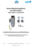
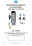
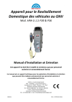
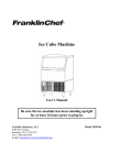
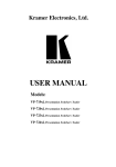
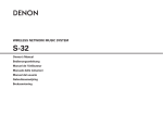
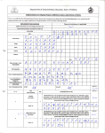
CNG Vehicles Refueling Appliance
Mod. FMQ 2 P30 & P36 - FMQ 2.5 P30
User’s Manual
STAMP OF AUTHORIZED TECHNICAL SERVICE
39.0044
Rev.2_ENG,February 2013 – FMQ 2 User Manual
Page1
BRC - FuelMaker - M.T.M. S.r.l. U.
Via Industria, 6 - 12062 - Cherasco - CN - ITALY
International Technical Assistance
Tel. +39.0172.48.68.628 0172.48.68.363 - 0172.48.68.623.- Fax +39.0172.486.630
e-mail: [email protected] - www.brcfuelmaker.it
North America – Canada Technical Assistance
Tel. +1.705.341.19.23
e-mail: [email protected]
39.0044
Rev.2_ENG,February 2013 – FMQ 2 User Manual
Page1
INDEX
1.
SAFETY INSTRUCTIONS ...................................................................................................................................... 3
2.
INTRODUCTION ................................................................................................................................................. 5
3.
TECHNICAL SPECIFICATIONS .............................................................................................................................. 5
4.
GENERAL INFORMATION ................................................................................................................................... 6
5.
USER’S CONTROL PANEL .................................................................................................................................... 8
6.
OPERATING INSTRUCTIONS ............................................................................................................................... 9
7.
DIAGNOSTICS ...................................................................................................................................................11
8.
MAINTENANCE INSTRUCTIONS .........................................................................................................................16
9.
VRA REMOVAL .................................................................................................................................................16
10.
DISPOSAL..........................................................................................................................................................17
11.
INSTALLATION DETAILS ....................................................................................................................................18
12.
CE CONFORMITY DECLARATION .......................................................................................................................20
TABLES INDEX
TABELLA 1- TECHNICAL SPECIFICATIONS ....................................................................................................................................... 5
TABELLA 2 – PRESSURE STOP MOD. P30 .................................................................................................................................... 7
TABELLA 3 – PRESSURE STOP MOD. P36 ..................................................................................................................................... 7
TABELLA 4 – STANDARD SET ...................................................................................................................................................... 7
TABELLA 5 – OPERATING INSTRUCTIONS ...................................................................................................................................... 9
TABLE 6 –INDICATION OF REGULAR WORKING ON USER’S PANEL (NORMAL MODE) ............................................................................... 9
TABLE 7 – INDICATION ON ANOMALIES ON USER’S PANEL (ANOMALIES MODE) .................................................................................. 10
TABLE 8 – INDICATION ON ANOMALIES ON USER’S PANEL (ERROR MODE) ......................................................................................... 10
TABLE 9 - “ANOMALIES MODE DIAGNOSTIC” (GREEN LIGHT BLINKING) ........................................................................................... 11
TABELLA 10 - “ERROR” MODE DIAGNOSTICS (GREEN LIGHT BLINKING) (CONTINUE) ................................................................... 15
PICTURES INDEX
PICTURE 1 – COMPRESSOR DESCRIPTION ..................................................................................................................................... 4
PICTURE 2 – USER PANEL ......................................................................................................................................................... 8
39.0044
Rev.2_ENG,February 2013 – FMQ 2 User Manual
Page2
1.
SAFETY INSTRUCTIONS
• READ CAREFULLY BEFORE INSTALLATION
Please read carefully the VRA and its additional components handbook before installation and use. In case of doubts
or problems during installation, please contact BRC FuelMaker Technical Support.
• LOCATION OF Vehicle Refueling Appliance (VRA)
VRA should only be installed outdoors and in safe areas.
Do not install it under or next to a window or protuberance that can cause gas accumulation. Leaves, snow or other
material should not obstruct air inlets. VRA and vehicle gas cylinder should be at the same ambient temperature
during refueling operation.
• REFUELING APPLIANCE FOR CNG (Compressed Natural Gas) VEHICLES ONLY
Do not use VRA for any other purpose or it may results in serious injury or even death to people and serious damages
to structures. Vehicle gas cylinder should be certified for storing CNG at a 250 Bar pressure or higher. VRA is suitable
for residential or commercial applications, always complying with Competent Authority requirements.
• REFUELING INSTRUCTIONS
Park your vehicle, switch it off and apply hand brake. Do not refuel with engine on and be sure that any possible
priming source is absent. Do not smoke or use naked flames during refueling. People or animals should not stay into
the vehicle during refueling.
• IF YOU SMELL GAS
Close immediately the manual valve on CNG supply line and, if possible, the vehicle cylinder one too. Switch off any
possible priming source and contact the Authorized Technical Center.
• REFUELING PIPE
Refueling flex pipe should be protected from damage and abrasion. After refueling your car, be careful to arrange it so
that it cannot be trampled. In case of pipe or connector abrasions or wear, contact the Authorized Technical Center
for its overhauling/replacement.
WARNING: DO NOT USE SOLVENT OR AGGRESSIVE CHEMICAL AGENTS FOR CLEANING THE OUTSIDE. USE
DETERGENTS OR DOMESTIC GENTLE SOAP.
39.0044
Rev.2_ENG,February 2013 – FMQ 2 User Manual
Page3
Picture 1 – Compressor Description
User’s Cover
Pipes Housing Pocket
User’s Panel
Refueling pipes
Padlock with key
(Optional)
Refueling pipes
Slides
Supply / Breather
Group
Outlet
Air Grille
Inlet
Air Grille
Maintenance
Cover
Maintenance
Cover Block
Fixing legs
39.0044
Rev.2_ENG,February 2013 – FMQ 2 User Manual
Page4
2.
INTRODUCTION
Model FMQ 2 P30 and FMQ 2.5 P30 have been developed for compressing Natural Gas for Automotive use and being
used outdoors with no lubricant oil.
The following versions are available:
Direct Refueling - Directly connecting One or Two refueling pipes to the unit;
Remote Refueling - Using one or more Remote Control or Auxiliary (Optional) Panels and connecting one or two
refueling pipes to each panel;
Fast Refueling - Using a Storage System (Optional) with Remote Control, Auxiliary or Priority Panel (Op)
FMQ is equipped with a temperature automatic compensation system and stops when the maximum filling pressure
determined by the ambient temperature detected by sensor situated into the air inlet is achieved.
VRAs are air-cooled and operating temperature range is -40° C +45° C.
Ventilation system is based on a fan situated in the inside lower part: the air enters from the rear side grille and exits
from the front side one (see pict. 2). The covering has some pivots allowing easy access to the unit modules and to the
quick-disconnect device of refueling pipes (see pict. 4).
User’s Panel controls VRA Start, Stop and monitoring (see pict. 5).
NOTE: Appliances equipped with Automatic Restart System (Optional) have AGA certification for commercial
and industrial use for USA only.
3.
TECHNICAL SPECIFICATIONS
GAS CIRCUIT
FMQ 2 P30
FMQ 2 P36
FMQ 2.5 P30
Max Filling Pressure
207 bar (3000 psig) at 20° C ambient
207 bar (3000 psig) at 20° C ambient
248 bar (3600 psig) at 20° C ambient
Min Inlet Pressure
0.017 bar (7” w.c.)
0.017 bar (7” w.c.)
0.017 bar (7” w.c.)
Max Inlet Pressure
0.035 bar (14” w.c.)
0.035 bar (14” w.c.)
0.035 bar (14” w.c.)
2.2 sm /h at 21°C - 0.017 bar inlet
2.8 sm /h at 21°C - 0.017 bar inlet
2,2 sm3/h at 21°C - 0.017 bar inlet
Electrical Supply
220 Volt AC Monophase, 50/60 Hz
220 Volt AC, Monophase, 50/60 Hz
220 Volt AC, Monophase, 50/60 Hz
Wiring Circuit Capacity
15 Amp
15 Amp
15 Amp
Full Load Amperes
6.5 Amp
7.3 Amp
7.0 Amp
Average Consumption
0.9 kWh
1.2 kWh
1.4 kWh
Dimensions (L x P x A)
540 x 500 x 990 mm
540 x 500 x 990 mm
540 x 500 x 990 mm
Weight
66 Kg
66 Kg
66 Kg
Noise
49 dBa at 5 mt.
49 dBa at 5 mt.
49 dBa at 5 mt.
Operating Temperature
From - 40° C to + 45° C
From - 40° C to + 45° C
From - 40° C to + 45° C
Nominal Flow
3
3
WIRING CIRCUIT
MECHANICS
Tabella 1- Technical Specifications
39.0044
Rev.2_ENG,February 2013 – FMQ 2 User Manual
Page5
4.
GENERAL INFORMATION
- Vehicle Refueling Point
While installing VRA, consider that it should be installed next to the vehicle to refuel because of the automatic
compensation system between outlet and ambient temperature pressures; always consider that refueling pipe length
can be of 3 mt., 4,5 mt. or 7,5 mt. and remember that sum of the two pipes connected to a same appliance should not
pass the total length of 9 mt. Moreover, refueling or outlet pipe should not obstruct pedestrian crossing or passages.
- Automatic Restart System
VRAs equipped with “Automatic Restart System” (Optional) will automatically go on with refueling operation when
outlet pressure will be lower than the unchangeable one set up by the builder. All VRAs are equipped with an
automatic temperature compensation system; they will automatically stop when the max pressure is achieved,
defined by ambient temperature detected by sensors installed on VRA itself (see table 3). If VRA is connected to a
storage system, the system will check the outlet pressure line and restart compressor in case of pressure fall (value set
up through the software).
- Protection against Bumps
VRA should not be placed at the risk of collision with vehicle. VRA should be protected by a steady structure; if not
present, you can use a structure fixed for 1 mt. into the floor. Always make reference to local laws in force.
- Refueling Pipes Length
Expansion tank has been planned to contain gas volume of refueling fitting and pipe that, in the presence of two pipes
connected, cannot pass the total length of mt. 9, assuring so a max internal pressure of 3 barg. In case of a bigger
volume, a safety valve situated inside the expansion tank will open discharging so the overpressure. Max internal gas
3
volume of refueling fittings should not exceed 5 cc . If Remote Control or Auxiliary Panels are present, please make
reference to installation handbook to check the pipes max length allowed.
NOTE Measured mentioned before should be respected to avoid the expansion tank overpressure and the
internal safety valve opening every time compressor stops.
- Discharge system
Breather line allows discharging possible system overpressures; this is the reason why it is very important keep it free
from dirt, material or ice.
System is set up for the direct refueling, that’s to say that software constantly controls refueling pipe pressure
increase in order to find possible leakages due to anomalies (e.g. refueling pipe broken, faulty refuelling point or
fitting). VRA considers a“leakage” when pressure does not increase of a defined value. Software calculates this value
through an algorithm. System is set up for a max filling volume of 280 lt. If possible, we suggest to decrease this
parameter to 140 lt. Regularly you never exceed 280 lt; only if strictly necessary, or if VRA is connected to a storage
system bigger than 280 lt., Monitoring of Pressure Increase parameter should be modified to OFF. In this case,
eventual leakages from outlet pipe will not be controlled.
39.0044
Rev.2_ENG,February 2013 – FMQ 2 User Manual
Page6
Pressione di Arresto Vs.
Temperatura Ambiente
207 ± 7.0 bar
183 ± 7.5 bar
166 ± 8.0 bar
150 ± 8.5 bar
133 ± 9.0 bar
116 ± 9.5 bar
100 ± 10.0 bar
Tabella 2 – Pressure stop Mod. P30
Pressione di arresto
248 ± 7.0 bar
232 ± 7.5 bar
210 ± 8.0 bar
188 ± 8.5 bar
165 ± 9.0 bar
143 ± 9.5 bar
121 ± 10.0 bar
Tabella 3 – Pressure Stop Mod. P36
Impostazioni di Fabbrica
Monitoraggio Incremento di Pressione
Volume Massimo Riempimento (Lt.)
Porta Elemento Ausiliare
Tabella 4 – Standard Set
39.0044
Temperatura ambiente
21° C o superiore
10° C
0° C
- 10° C
- 20° C
- 30° C
- 40° C
Temperatura ambiente
15° C o superiore
10° C
0° C
- 10° C
- 20° C
- 30° C
- 40° C
SI
280
NO
Rev.2_ENG,February 2013 – FMQ 2 User Manual
Page7
5.
USER’S CONTROL PANEL
User’s Control Panel can be reached through the User’s Cover.
Panel has two buttons, START and STOP, and three LEDs, Yellow, Green and Red indicating many different situations.
See following pages for VRA Error or Condition Codes.
Picture 2 – User panel
39.0044
Rev.2_ENG,February 2013 – FMQ 2 User Manual
Page8
6.
OPERATING INSTRUCTIONS
Tabella 5 – Operating Instructions
1)
With engine off, check the absence of danger, connect Refueling Pipe to the vehicle
refueling point and verify the good connection by pull it slightly.
2) Push the START button. VRA will start working.
3) If compressor stopped automatically go to the next step; if you need to stop refueling,
press the STOP button.
4) Disconnect Refueling Pipe from vehicle and arrange it into the suitable lateral pocket
under the upper cover.
CHECK THE RIGHT WORKING OF USER’S CONTROL PANEL INDICATORS (Only with VRA in stand-by)
Keep the STOP button pressed for a while in order to check the right user’s control panel LEDs working. LEDs will
sparkle for roughly 1 second before they turn off.
Table 6 –Indication of regular working on user’s panel (Normal mode)
INDICATION
DESCRIPTION
No light
- Ready to start
- Electrical Supply Missing
- Replace Fuses
Note: If electrical supply fails for less than 15 sec., VRA will restart automatically when
it will be back.
- Refueling ended
Fixed Yellow
Light
Vehicle tank has been fully filled up at the max pressure allowed, you can disconnect it
from the refueling pipe.
VRA restarts by pushing the START button.
Fixed Green
Light
39.0044
- Refueling
VRA is filling up the vehicle.
Rev.2_ENG,February 2013 – FMQ 2 User Manual
Page9
Table 7 – Indication on anomalies on user’s panel (Anomalies mode)
INDICATION
Blinking Yellow
Light
DESCRIPTION
- Electrical Supply Missing
During refueling, electrical supply failed for more than 15 sec. Push the START button to
restart VRA.
- Anomaly
VRA stopped in an anomalous way.
Most common reasons of the Anomaly are:
Blinking Green
Light
- Connection to the vehicle is faulty or damaged.
- Inlet pipe Manual Valve is closed.
- Air inlets are obstructed.
- Refueling pipe is faulty (e.g. leakage).
- Max refueling time has been passed (25 hours non-stop).
VRA can be restarted regularly if error has been reset.
WARNING:
Cylinder/s with a capacity of more than 140 lt. may need more than 25 hours to refuel in some special conditions (e.g.
high ambient temperature, next compressor scheduled maintenance intervention, etc.).
In this case VRA will stop for Anomaly because it will consider the max refueling time passed as a gas leakage. If after
inspection VRA working is regular, you can restart compressor.
Table 8 – Indication on anomalies on user’s panel (Error mode)
INDICATION
DESCRIPTION
- Call Technical Assistance
Blinking Red
Light
Automatic safety device found and error that can be dangerous and stopped the
system with no possibility to restart. You need to call technical service for authorized
personnel intervention.
Blinking Yellow, Green and
Red Light
(at the same time)
- Failure or Hour meter Missing
Blinking Yellow, Green and
Red Light
(sequentially)
- Automatic Block System
39.0044
Automatic safety device stopped the system because of failure or Hour meter missing.
Automatic safety device blocks VRA for 15 sec. and stops it from restarting. After 15
sec you can regularly restart VRA.
Rev.2_ENG,February 2013 – FMQ 2 User Manual
Page10
7.
DIAGNOSTICS
VRA is equipped with an Anomaly Detection Software, both in ERROR (Blinking Green LED) and in SUPPORT REQUEST
(Blinking Red LED) mode).
The following tables show error codes and possible corrective actions.
Numbers 0 - 1 - 2, correspond to the following conditions.
0 = Indicator Off
1 = Indicator Fixed
2 = Indicator Blinking
Keep the STOP button pressed to identify the reason for ERROR or SUPPORT REQUEST.
LEDs will sparkle just like a working control, then hours code will appear.
Table 9 - “Anomalies mode Diagnostic” (Green Light Blinking)
ERROR
DESCRIPTION
CORRECTIVE ACTION
CODE
Failure of supply, Electronic Module error or Check LEDs working by keeping the STOP button
0
error loss.
pressed. LEDs should light on and sparkle.
0
If OK, try to restart VRA.
0
0
Excessive Engine Temperature
0
If OK, try to restart VRA.
1
Inadequate increase of refueling pressure at
the beginning of filling cycle and lower than
20 barg (290 psig)
0
1
0
If error persists, contact authorized support centre.
Check that air grilles are free.
7 minutes if set up to 280 lt. (74 US US gal.)
If error persists, contact authorized support centre.
Check the right connection between refueling fitting
and vehicle.
If OK, check that total volume of tank is not bigger than
140 lt. (37 US gal.). VRA max volume setting could be
changed, so technical service intervention is necessary.
If OK, check possible leakages from refuelling pipe. If no
leakages are detected, try to restart VRA.
If error persists, contact authorized support centre.
39.0044
Rev.2_ENG,February 2013 – FMQ 2 User Manual
Page11
Table 9 - “ERROR” MODE DIAGNOSTICS (Green Light Blinking) (Continue)
ERROR
CODE
DESCRIPTION
Pressure Drop (over 20 barg. (290psig)) in
High Pressure system.
CORRECTIVE ACTION
Check possible leakages from refuelling pipe.
If OK, start VRA without connecting refueling fitting.
Wait for VRA automatic stopping.
0
1
1
0
If VRA works for more than 1 minute without refueling
fitting connection, contact authorized support centre.
Error code 011 can appear even in the following cases:
- If you connect a second vehicle while VRA is working or if one of the two vehicles connected to the
unit presents some problems to the non-return valve (valve blocked).
- In case of ice into the refueling pipe that could obstruct non-return valves. Low temperatures and
wet gas composition can contribute to create ice.
Auxiliary Component Block.
Check connectors and cables of auxiliary component, if
(External Interlock)
installed (E.g. External Gas Sensor).
2
If error persists, contact authorized support centre.
1
1
Ambient temperature too high or too low, or
If the cause has been the ambient temperature lower
temperature sensor error .
than -45° C or higher than +45° C, try to restart VRA.
0
If error persists, contact authorized support centre.
0
Inadequate inlet pressure.
1
Check that inlet manual valve is open.
If error persists, contact authorized support centre.
0
1
1
0
Excessive
internal
temperature
or Check that air inlets (the front and the rear one) are
temperature sensor error while VRA is clean and free from material obstructing them.
refueling.
If error persists, contact authorized support centre.
2
STOP button sequence error
1
Try to push the Stop button again and to restart VRA.
If error persists, contact authorized support centre.
1
0
39.0044
Rev.2_ENG,February 2013 – FMQ 2 User Manual
Page12
Table 9 - “ERROR” MODE DIAGNOSTICS (Green Light Blinking) (Continue)
ERROR
CODE
DESCRIPTION
Electronic error.
CORRECTIVE ACTION
Try to push the Stop button again and to restart VRA .
1
If error persists, contact authorized support centre.
1
1
Electronic error.
Try to push the Stop button again and to restart VRA .
1
1
1
1
If error persists, contact authorized support centre.
Working hours record missing during the last Try to disconnect electric supply for 1 minute and
failure of electric supply.
connect it again. Try to restart VRA.
1
If error persists, contact authorized support centre.
2
Engine Control Error.
Try to disconnect electric supply for 1 minute and
connect it again. Try to restart VRA.
1
2
If error persists, contact authorized support centre.
0
1
2
1
Excessive increase
refueling operation.
of
pressure
during Check the good connection between vehicle and
refueling fitting, the absence of narrowing and try to
restart VRA.
If error persists, contact authorized support centre.
Max refueling time passed (more than 25 Check that total volume of tank is not bigger than 140 lt.
hours )
(37 US gal.). VRA max volume setting could be changed,
so technical service intervention is necessary.
1
2
If tank volume is ok, check possible leakages. In case of
leakages, contact authorized support centre.
2
If there are no leakages, restart VRA.
If error persists, contact authorized support centre.
39.0044
Rev.2_ENG,February 2013 – FMQ 2 User Manual
Page13
Table 9 - “ERROR” MODE DIAGNOSTICS (Green Light Blinking) (Continue)
ERROR
CODE
2
DESCRIPTION
CORRECTIVE ACTION
Electric supply Failure.
Restart VRA.
Expansion Tank Overpressure
If disconnecting fitting from vehicle results difficult,
close the valve between tank and engine; switch the
engine on and wait for its stopping.
0
0
2
0
Open valve again and restart: push the Stop button.
If error persists, contact authorized support centre.
1
2
1
0
Inadequate Pressure Increase after 6 minutes Check possible leakages on refueling pipe or fitting.
of working or with tank pressure bigger than
20 barg (290 psig)
If there are no leakages, close gas supply valve and
start VRA. Unit should stop in roughly 1 min. showing
14 minutes with tank volume settingh at 280 the error code 101.
lt. (74 US gal.).
If OK, open supply valve again and restart VRA.
Hour Meter Error
If error persists, contact authorized support centre.
Restart VRA.
2
2
If error persists, contact authorized support centre.
0
39.0044
Rev.2_ENG,February 2013 – FMQ 2 User Manual
Page14
“SUPPORT REQUEST” MODE DIAGNOSTICS (Red Light Blinking)
Keep the STOP button pressed. LEDs will blink first at the same time, then they will light on showing one of the error
codes of the following table.
VRA can record up to 5 errors; you can see them by keeping the STOP button pressed and pressing then the START one,
until the code 222 will appear (end of error archive). Corrective actions for this kind of error can only be carried out by
authorized personnel.
Table 1010 - “ERROR” MODE DIAGNOSTICS (Green Light Blinking) (Continue)
ERROR
CODE
0
DESCRIPTION
CORRECTIVE ACTION
Expansion Tank Overpressure.
Contact authorized support centre.
High Pressure Transductor error.
Contact authorized support centre.
Engine Module Error.
Contact authorized support centre.
Hour Meter Error
Contact authorized support centre.
End of Error Archive
No action required
1
2
0
2
0
1
2
0
2
2
0
2
2
2
39.0044
Rev.2_ENG,February 2013 – FMQ 2 User Manual
Page15
8.
MAINTENANCE INSTRUCTIONS
INTRODUCTION TO MAINTENANCE
Final user or unauthorized personnel should not access internal components for safety reasons. VRA should only kept
maintained by authorized personnel suitably trained by BRC FuelMaker.
Before contacting Technical Support Centre, User should always verify error code on User’s Panel and possess
installation documents.
WARNING:
Any other operation not described in this manual should only be carried out by BRC-FuelMaker at its premises. Any
intervention realized by UNAUTHORIZED personnel will invalidate the warranty and cause damages to the compressor
and serious injury or even death to people.
- Ordinary Maintenance Inspection
Periodically
check that outlet pressure corresponds to parameters indicated by suitable table;
check that refueling pipe does not show abrasions, cutting or swelling; if necessary, call technical service to
replace it. Check that vehicle connector seal (O.R) does not show damages or cutting.
check that breather system and front/rear air inlets are free from dirt, material or ice.
Special technical service for the following modules should only be carried out by BRC-FuelMaker at its premises.
- Compressor Module (CPQ)
- Control Module (CUQ)
- Electronic Circuit Board (EMQ)
- Fan
Attempt to tamper with or open modules can cause damages to infrastructures, serious injury or even death to
people, and obviously invalidate the warranty.
For further information, please feel free to contact Technical Service.
9.
VRA REMOVAL
If you need to remove the whole unit, follow these instructions:
•
•
•
•
Check that Electric Supply button is OFF and gas inlet valve closed.
Check the absence of voltage on electric supply cable and disconnect it
Disconnect Inlet and Discharge pipe from VRA verifying the absence of overpressures; close fittings.
Pack VRA with its original packaging.
For further information, please feel free to contact Technical Service.
39.0044
Rev.2_ENG,February 2013 – FMQ 2 User Manual
Page16
10. DISPOSAL
RIGHT DISPOSAL
At the end of the VRA’s life, it should be removed and disposed according to installation Country
laws in force.
A suitable separate collection for the following recycle and environmental disposal helps to avoid
possible negative effects on environment and health and favours re-use and/or recycle of VRA
materials.
DO NOT DISPOSE COMPRESSOR TOGETHER WITH DOMESTIC WASTE
PHILL CONTAINS MATERIAL ABSORBING MERCAPTAN FROM NATURAL GAS DURING
REFUELING OPERATIONS
----------------------------------------------------------------------------------------------------------------------------------Waste from Electrical and Electronic Equipment (WEEE)
(Valid for European Union and other European Countries
with waste separate collection systems)
This symbol
on VRA or on its documents means that
product should be disposed at the end of its life according
to directive 2002/96/CE about waste from Electrical and
Electronic Equipment (WEEE) and implementation in
national law.
VRA should not be disposed as urban waste but rather be
delivered to the suitable collection point for electrical and electronic equipment.
Phill contains material absorbing mercaptan from natural gas durint refueling operations.
In case of wrong VRA disposal, you will be responsible for it in accordance with laws in force.
For further information about disposal and recycle of VRA please contact authorised offices or call
BRC FuelMaker.
39.0044
Rev.2_ENG,February 2013 – FMQ 2 User Manual
Page17
11. INSTALLATION DETAILS
Authorized Retailer ______________________________________________________
Installer ________________________________________________________________
Telephone Number_______________________________________________________
Date of Installation ______________________________________________________
FMQ Serial Number _____________________________________________________
CONFIGURATION
Inlet Pressure
mBar _____________________
Pressure Reducer
YES
NO
Max Filling Capacity
140 Lt.
280 Lt.
Pressure Increase Monitoring
YES
NO
Auxiliary Element Port Enabled
YES
NO
Auxiliary Element (Gas Sensor, Remote Panel, Other)
_______________________________
_______________________________________________________________________
Anti-tearing Disconnection Device
1
Storing
NO
YES
Date of Start _________________
39.0044
2
Adapt.
Lt. ______________________
Installer’s Signature________________________
Rev.2_ENG,February 2013 – FMQ 2 User Manual
Page18
WARRANTY CERTIFICATE
WARRANTY CONDITIONS
M.T.M. Srl guarantees products for 24 months starting from the date of purchasing, within the limit of 2,000
working hours.
Purchasing should be proved by a fiscally valid receipt issued by the seller (fiscal ticket, invoice or transportation
bill) identifying the product, the date of purchasing and/or delivery.
During the whole warranty period M.T.M. Srl engages itself to:
(a) restore faulty products assuming all burdens of expenses concerning spare parts and transportation
(b) replace faulty products not usefully repairable (e.g. when repair will cost more than replacement).
GENERAL CONDITIONS
In order to benefit from warranty, the user will contact the seller and/or installer that will repair the machine
having ascertained the working defect.
If seller and/or installer cannot solve the problem, the machine will be forwarded to BRC FuelMaker that will repair
it or replace it with a new one at its own discretion.
The machine will be returned to BRC FuelMaker in its original packaging; lack of this packaging will automatically
cause the warranty forfeiture.
Warranty will be acknowledged only if the purchasing receipt will be sent by fax or mail at the moment of the
intervention request:
BRC FuelMaker – Warranty Dept
Fax: 0172.486.630
E.mail: [email protected]
This warranty will not cover:
a) Fair wear and tear
b) Damages deliberately caused or due to negligence
c) Damages caused by inobservance of working instruction or by a wrong installation
d) Damages on non-functioning components that do not jeopardize the regular machine work, scratches and
difference in colours included
e) Accidental damages caused by foreign body or substance, especially included the non-standard composition
of the gas supplied to the machine (gas quality).
f) Repairs carried out by unauthorized assistance centres or repairs realized with non original spare parts
g) Damages caused by transportation
For further information or in case of need please call Toll Free Number 800 128 821
39.0044
Rev.2_ENG,February 2013 – FMQ 2 User Manual
Page19
12. CE Conformity declaration
39.0044
Rev.2_ENG,February 2013 – FMQ 2 User Manual
Page20