1
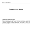
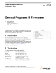
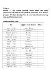
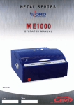
OG7005
Solid Top
Gas Oven Range
USER, INSTALLATION, SERVICING AND
CONVERSION INSTRUCTIONS
For use in GB & IE
IS323 ECN3145
1
Dear Customer,
Thank you for purchasing this Lincat product.
This is just one of over 300 different items of catering equipment available
which is constantly being extended and improved. Details are available from
your local distributor or direct from us.
Used for the purposes for which it is intended, and with careful maintenance
as outlined in this User Guide, your Lincat product will give you years of
trouble free service.
IMPORTANT INFORMATION
Please read all of the safety and operating instructions carefully before using this
product. Please pay particular attention to all sections of this User Guide that carry
warning symbols and notices.
WARNING!
This is a Warning symbol. This symbol is used throughout the user guide
whenever there is a risk of personal injury. Ensure that these warnings are
read and understood at all times.
CAUTION!
This is a Caution symbol. This symbol is used throughout the user guide whenever
there is a risk damaging your Lincat product. Ensure that these warnings are read
and understood at all times.
NOTE:
This is a Note symbol. This symbol is used throughout the user guide to provide additional
information, hints and tips.
IS323 ECN3145
2
CONTENTS
Contents
Page
Customer Information……………………………………………………….
Warnings and Precautions…………………………………………………
Technical Data………………………………………………………………..
Commissioning……………………………………………………………….
Check List of Enclosures…………………………………………………..
Installation…………………………………………………….………………
Conversion of Gas Types…………………………………………………..
User……………………………………………………………………………..
Servicing ………………………………………………………………………
Component Replacement ………………………………………….………
Spare Parts List………………………………………………………………
Fault Finding………………………………………………………………….
Service information…………………………………………………………..
Guarantee………………………………………………………….…………..
2
3
4
5
5
6
7-10
11
12
12-13
14
15
16
16
WARNINGS AND PRECAUTIONS
It is mandatory that all appliances are installed, commissioned and serviced by a qualified and
competent person as defined by the regulations in force in the country of installation.
Failure to comply will invalidate the warranty.
WARNING!
This appliance must be installed by a competent installation engineer in accordance with the
installation instructions, and should conform to the following requirements:
Do not obstruct or block the appliance flue.
Installation must include sufficient ventilation to prevent the occurrence of unacceptable
concentrations of substances harmful to health in the room in which they are installed.
It is recommended that this appliance is sited under an extraction canopy for the removal of
combustion products
After operation, some parts of the appliance will remain hot for a period of time. Please take
care to avoid accidental burns.
CAUTION!
All equipment must be earthed to prevent shock.
Do not connect directly to any flue, ducting or mechanical extraction system.
Installation should allow for a sufficient flow of fresh air for gas combustion.
Parts which have been protected by the manufacturer or his agent must not be adjusted by the
installer or user.
IS323 ECN3145
3
TECHNICAL DATA
OG7005
Model
Dimensions
Overall height (mm)
Width (mm)
Depth (mm)
Weight (kg)
Hob cooking surface w x d (mm)
Usable oven capacity w x d x h (mm)
Oven shelf size (mm)
950
600
760
113
900 x 600
710 x 540 x 400
710 x 540
Heat Input
Total heat input Natural(Gross)
Total heat input Propane(Gross)
Oven rating Natural(Gross)
Oven rating Propane(Gross)
Hob rating Natural(Gross)
Hob rating Propane (Gross)
18.0 kW
17.5 kW
9.5 kW
7.0 kW
8.5 kW
8.5 kW
Connection and Operating Pressures
Gas inlet connection
Supply Pressure - Natural
Operating Pressure - Natural
Supply Pressure - Propane
Operating Pressure - Propane
Gas Consumption
Total gas rate – Natural
Total gas rate – Propane
Hob burner gas rate - Natural
Hob burner gas rate - Propane
Oven burner gas rate - Natural
Oven burner gas rate - Propane
3
-1
1.72 m h
-1
1.25 kg h
3 -1
0.81 m h
-1
0.61 kg h
3 -1
0..91 m h
-1
0.64 kg h
Oven temperature range
IS323 ECN3145
½” BSPT Male (when nipple is fitted)
20mbar
17mbar
37mbar
27 mbar
≈140 – 260 °C
4
COMMISSIONING
PREPARATION
Remove all packaging and protective coatings prior to installation.
Check that the burner caps have been fitted correctly to the burner body.
VENTILATION
The area in which this equipment is to be installed should have sufficient fixed ventilation to comply
with local legislation requirements. It is recommended that a room, or internal space, be provided
with a minimum free area of 4.5cm2 per kW (3,400Btu/hr) of total heat input.
CHECK LIST OF ENCLOSURES
Please ensure the following items are included with this piece of equipment:
Model
Warranty Card
Pressure Governor
Bulls Eye Iron
Connection Nipple (1/2" BSP)
Ignitor Wand
User Instructions
OG7005
1
1
1
1
1
1
Tick
SERIAL NUMBER
NOTE
Each appliance manufactured at Lincat has a unique identifying number found in the top
right hand corner of the data plate attached at the rear of the appliance. Please record that
number in the space provided should it be required for future reference.
Serial Number
MARK OF CONFIDENCE
Every singe product that leaves our factory bears a serial plate showing the assembler’s
initials. It’s a mark of confidence we have in our people and our manufacturing
process.
IS323 ECN3145
5
INSTALLATION
SITING
The installer must ensure that all regulations are met and that there is an unobstructed minimum
distance of 1000mm from the top of the flue to the ceiling, which must be of non-combustible
material.
The appliance should be installed on a level surface ensuring the unit is stable and firmly located.
Any partitions, walls or kitchen furniture in close proximity must be of non-combustible materials
and not be closer than 50mm from the sides and rear of the flue.
GAS SUPPLY AND CONNECTION
The gas inlet connection is at the rear of the appliance. The 1/2" nipple (supplied) is to be fitted to
the inlet connection. When the nipple is fitted the pressure regulator (supplied) is to be fitted to the
nipple ensuring flow through the regulator is in the correct direction as denoted on the base of the
regulator. All joints made must be leak free.
Final gas connection to the appliance and gas supply shall comply with local regulations.
When making the connection to the appliance an isolating cock should be fitted into the supply line
close to the unit, for emergency shutdown or servicing purposes.
SUPPLY PRESSURES
• To gain access to the gas pressure test nipple the fascia panel requires removal. The test
nipple is situated in the centre of the manifold rail.
• Remove the blanking screw and attach a pressure gauge to the boss of the test nipple.
• Light all the burners with the oven thermostat set to maximum.
• Adjust the pressure at the governor. See table below.
LOCKING OF WHEELS
When the appliance has been installed in its intended position the front casters should be locked by
depressing the locking tabs on the castors.
Locks should only be released for the intention of moving the appliance for cleaning
purposes and or routine servicing of the appliance.
IS323 ECN3145
6
CONVERSION OF GAS TYPES
Conversion of Gas Type – Injector Changes
Model
Gas
Inlet Pressure
G20
20 mbar
G31
37 mbar
OG7005
∅
Injector
GG
C
Z
YY
F
TT
GG
C
Z
YY
F
TT
2.2
1.3
0.41
2.50
0.80
0.40
1.55
0.80
0.24
1.70
0.6
0.25
Mark
220
130
41
860
80
40
155
80
24
360
60
25
Part No.
JE103 x 1
JE127 x 1
JE105 x 1
JE64 x 1
JE122 x 1
JE66 x 1
JE104 x 1
JE120 x 1
JE106 x 1
JE71 x 1
JE123 x 1
JE55 x 1
Regulated
17.0 mbar
all burners
on full
27.0 mbar
all burners
on full
AA
Fascia Panel
Removal
BB
AA
FF
CC
DD
EE
FF
•
•
•
Remove the hot plates AA and the bulls eye BB. Remove the fascia panel securing screws FF
located along the front edge of the hob top.
Remove the control knobs DD.
Remove the lower fascia panel screws FF from the underside of the panel. Access is gained
by opening both oven doors.
Care should be taken when removing the fascia panel as the oven ignitor lead will be
attached to the ignitor. Carefully remove the lead from the ignitor and temporarily tie to the
manifold rail.
•
The test nipple EE is situated on the main manifold rail as detailed.
IS323 ECN3145
7
Hob Valve Bypass Injectors
• Remove the fascia panel as detailed on page 7.
• Remove the bypass injector C from the hob burner control valve B.
• Replace the bypass injector applicable to the required gas type. Screw fully home but do not
over tighten.
E
A
B
C
D
E
Part
Hob Tap Components
Description
Manifold
Gas tap
Bypass injector
Clamp screw
Elbow
C
B
A
D
Hob Burner Injectors
• Remove the fascia panel as detailed on page 7.
• Loosen the grub screw AA at the venturi inlet to release the injector housing BB.
• Draw the flexible hose and injector housing to the front of the appliance.
• Replace the hob burner injector CC applicable to the required gas type.
• Fit and secure the injector housing to the venturi.
• Repeat the procedure for remaining hob burners.
NN
MM
Hob Burner Components
Part
Description
FF
Injector housing
GG
Injector
HH
Grub screw
JJ
Retaining screws
KK
Venturi assembly
LL
Gasket
MM
Burner body
NN
Burner cap
IS323 ECN3145
LL
KK
GG
JJ
HH
8
FF
Hob Pilot Injector
• Remove hot plates and bull’s eye for access.
• Loosen and remove the pilot cover fixing screw.
• Replace the hob burner injector X applicable to the required gas type.
X
Y
Z
X
Y
Z
Part
ob Pilot Components
Description
Fixing screw
Pilot cover
Pilot injector
Oven Thermostat Bypass Injector
• Remove the fascia panel as detailed on page 7.
• Remove the bypass injector F from the oven thermostat valve G.
• Replace the bypass injectors applicable to the required gas type. Screw fully home but do not
over tighten.
G
• Re-Fit the ignitor lead, fascia panel and
control knobs.
F
A
D
G
F
Part
Oven Thermostat Components
Description
Manifold
Clamp screw
Thermostat
Bypass injector
IS323 ECN3145
A
D
9
Oven Burner and Pilot Injectors
Pilot Injector
• Remove the oven base tray and shelves.
• Loosen the pilot pipe-retaining nut RR and withdraw the pipe free from the pilot housing.
• Remove the pilot injector TT from the housing.
• Replace the pilot injector applicable to the required gas type.
• Re-fit the pilot pipe and secure the retaining nut.
Oven Burner injector
• Remove the nut PP at the rear of the oven burner.
• Remove the burner support bracket screw beneath the elbow.
• Remove the pilot bracket screws SS and withdraw the pilot assembly clear of the burner QQ
• Rotate the burner body QQ to gain access to the injector YY.
• Remove the injector, fibre washer WW and copper washer XX.
• Replace the injector applicable to the required gas type including the new washers supplied.
• Re-fit all components in reverse order.
VV
Oven Burner Components
Part
Description
PP
M5 nut
QQ
Burner
RR
Compression nut
SS
Pilot fixing nut
TT
Pilot injector
UU
Pilot assembly
VV
Elbow
WW
Fibre washer
XX
Copper washer
YY
Burner injector
ZZ
Lock nut
YY
ZZ
WW
XX
UU
TT
SS
RR
QQ
PP
IS323 ECN3145
10
USER INSTRUCTION
APPLIANCE USE
This appliance is only for professional use and should only be used by qualified personnel.
Ensure that the person responsible understands how to light, safely operate, clean and shutdown the
appliance and is made aware of the position and operation of the gas isolating cock in the event of an
emergency. All users should know how to clean burner caps and to correctly locate the burner cap on
the burner body.
LIGHTING SEQUENCE – HOB BURNER AND OVEN BURNER
• Open the main gas cock.
• Remove the bull’s eye plate for the hob and for the oven open the doors.
• Push in the relevant control knob then rotate anti-clockwise to the spark position to allow gas
through to the pilot. Manually light the hob pilot using a taper or piezo ignitor wand. For the
oven pilot depress the piezo ignitor repeatedly on the fascia panel until a flame is established.
• On establishing a flame at the pilot, keep the knob depressed for approximately 15 seconds
then release. The pilot should remain lit.
• Rotate to desired temperature setting to ignite the gas at the main burner.
SHUT DOWN
To shut down the appliance rotate all control knobs clockwise to the OFF position. The gas supply
stopcock or bottle valve should now be closed.
SOLID TOP PREPARATION
• Clean the protective coating from the solid top surfaces with a mild detergent.
• Light the hob burner to dry the surface then spread approximately 2kg of household salt
evenly over the surface.
• Run the unit on full for around 20 minutes until the salt discolours.
• Turn off the burners, allow the solid top to cool and remove and discard the salt.
• The solid top is now ready for use.
Note: The minimum temperature of the hottest point of the solid top (around the edge of the bull’s
eye) is approximately 3900 C.
CLEANING
Ensure the appliance is cool and the gas supply is isolated before commencing cleaning.
After use wash the unit down with a warm detergent solution.
Frequently check the burner cap ports for blockages. Clear as necessary.
Do not use abrasives on stainless steel or enamelled parts.
Do not use any products containing chlorine or hydrochloric acid to clean stainless steel
surfaces.
Do not clean the appliance using a water jet.
OPENING OF THE OVEN DOOR
Care must be taken to avoid injury when opening the oven door when the oven is in use as
hot air will rapidly escape.
IS323 ECN3145
11
SERVICING
SERVICE ACCESS
To access and service the gas control valves
• Remove the control knobs and fascia panel to gain access to the valves.
• Remove the two screws securing the valve boss and carefully withdraw the spindle
from the valve.
• Grease as necessary and refit parts. Carry out gas soundness check.
FASCIA PANEL REMOVAL
See page 7 for details
OPERATIONAL CHECK
Commissioning must include an operational check of all controls.
•
•
Check that each burner can be lit at both full rate and low rate.
Check that each burner will remain lit when turned to low rate.
COMPONENT REPLACEMENT
Hob Pilot Thermocouple
• Remove the control knobs, fascia panel, hot plates and bull’s eye.
• Remove the thermocouple lock nut at the pilot base.
• Remove nut thermocouple nut from valve body B.
• Withdraw the thermocouple.
• Fit the new thermocouple and re-assemble in the reverse order.
Oven Thermocouple
• Remove the control knobs and fascia panel.
• Remove the thermocouple nut from the thermostat body G.
• Remove the thermocouple lock nut from the pilot assembly and withdraw the
thermocouple from the bracket.
NOTE
• Tape the new thermocouple to the old thermocouple. Withdraw the old thermocouple
whilst feeding through the new thermocouple.
• Re-assemble in the reverse order.
Control Valve and Oven Thermostat
• Remove the control knobs and fascia panel.
• Remove the nut from the gas output at the valve or thermostat.
• Remove the nut from the pilot output at the thermostat.
• Remove the thermocouple nut from the valve or thermostat.
• Remove clamp screws D from the valve or thermostat.
• Free the thermostat bulb from the oven bracket and feed through the oven liner.
• Free the valve or thermostat from the manifold A.
• Fit the new valve or thermostat and re-assemble reverse order.
• Perform gas soundness test of circuit prior to operation of appliance.
IS323 ECN3145
12
Hob Burner
• Remove the control knobs and fascia panel.
• Remove the hot paltes and bull’s eye.
• Remove the burner cap NN
• Remove the burner body retaining screws JJ from the underside of the hob top.
• Fit the new burner body and re-assemble parts.
Oven Burner
• Remove the nut PP at the rear of the oven burner.
• Remove the burner support bracket screw beneath the elbow.
• Remove the pilot bracket screws SS and withdraw the pilot assembly clear of the burner QQ
• Remove the nut at the burner gas inlet elbow VV.
• Withdraw the burner.
• Remove the elbow from the burner.
• Fit the elbow to the new burner.
• Re-assemble in the reverse order.
• Perform gas soundness test of circuit prior to operation of appliance.
Oven Ignitor Electrode
• Remove the ignitor lead at the ignitor.
• Remove the ignitor retaining nut from at the pilot assembly.
• Replace the ignitor.
• Check that the ignitor is replaced correctly and ignites the pilot flame upon operation.
Piezo Ignitor
• Remove facia panel
• Disconnect the ignitor and ignitor earth leads.
• Remove the retaining nut and withdraw from unit.
• Replace and fit in reverse order.
IS323 ECN3145
13
SPARE PARTS LIST
Part number Part description
BE21
BU55
BU68
BU72
BU83
CA123
CA135
CO113
CP04
DO73
IG17
IG35
IG37
IR01
JE55
JE64
JE66
JE71
JE103
JE104
JE105
JE106
JE120
JE122
JE123
JE127
KN230
KN234
PG10
PI30
PI48
PI54
SH75
SI13
TC23
TH64
VA46
WA08
IS323 ECN3145
Bulls eye
Door bush (large)
Oven burner
Door bush (small)
Hob burner assembly
Breaked castor
Free running castor
Copper washer
Cast hot plate
Door catch assembly
Ignitor & lead (oven pilot)
Piezo ignitor
Ignitor lead (fascia earth)
Bulls eye iron
Oven pilot injector propane 0.25mm
Oven burner injector natural 2.5mm
Oven pilot injector natural 0.4mm
Oven natural propane 1.7mm
Hob burner injector natrual gas 2.2mm
Hob burner injector propane gas 1.55mm
Hob pilot natural 0.41mm
Hob pilot propane 0.24mm
Hob valve bypass propane 0.8mm
Oven thermostat bypass natural 0.8mm
Oven thermostat bypass propane 0.6mm
Hob valve bypass natural 1.3mm
Oven control knob
Hob control knob
Pressure regulator
Oven pilot assembly
Hob thermocouple
Hob pilot assembly
Shelf
Ignitor wand
Oven thermocouple
Oven thermostat
Hob valve
Fibre washer
14
FAULT FINDING
•
Piezo oven ignitor not sparking.
Check for a short in the high tension lead
Yes
No
Replace lead
Check electrode for fracture
•
Yes
No
Replace electrode
Replace piezo ignitor
Burner/s will not light or stay lit
Yes
Is there gas at the burner?
No
Check injector for blockages
Yes
Are thermocouple connections loose?
No
Tighten connections
Yes
Is the thermocouple voltage less than 15mV?
Replace thermocouple
Yes
Replace valve
IS323 ECN3145
15
No
Is the valve damaged?
Recheck system
No
SERVICE INFORMATION
Gas catering equipment should be routinely serviced to ensure a long trouble free life. It is
recommended that this appliance is serviced every 6 months by a competent gas engineer.
For help regarding the installation, maintenance and use of your LINCAT equipment, please call:-
LINCAT GROUP SERVICE HELP DESK
+44 (0) 1522 875520
AUTHORISED SERVICE AGENTS
We recommend that all servicing other than our authorised service agents carry out routine cleaning.
We cannot accept responsibility for work carried out by other persons.
Please quote both the model and serial numbers from the data plate attached to the unit. Give brief
details of the service requirement.
If possible please quote the product code of the part number you require.
Work carried out under warranty will normally be undertaken only during normal working hours, i.e.
Monday to Friday, 8.30 a.m. - 5.30 p.m.
CONDITIONS OF GUARANTEE
The guarantee does not cover:1)
2)
3)
Accidental breakage or damage
Operational misuse, wear and tear from normal usage, incorrect adjustment, or neglect.
Incorrect installation, maintenance, modification or unauthorised service work.
IS323 ECN3145
16