1
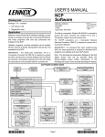
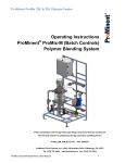
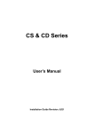
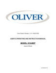
Page 1 of 25 TABLE OF CONTENTS 1. Before You Begin Disclaimer What Is Included Optional Accessories Unpacking Instructions Claims Contact Us 3 3 3 3 3 3 3 2. Safety Information Safety Notes Rules for Safe Hydraulic Operation Three Common Hydraulic System Hazards Ways to Prevent Hazards from Occurring Safety Locks Manual Cylinder Lock 4 4 4 4 4 5 6 3. Setup Assembly Recommended Tools 7 7 7 4. Operation Instructions Pre-Operation Maintenance Operation Instructions 11 11 11 5. Technical Information Product Maintenance 13 13 6. Technical Specifications Specifications Replacement Parts 14 14 15 7. Hydraulic Information (optional) General System Information Hydraulic Pump Information Radio Remote System Information Hydraulic Power Unit Diagram 19 19 19 19 19 8. Trouble Shooting and FAQs 20 Page 2 of 25 1. Before You Begin Disclaimer The information and specifications contained in this document are subject to change without notice. Safe-T-Pull Inc. assumes no responsibility or liability for any errors or omissions that may appear in this manual. Safe-T-Pull Inc. reserves the right to update the existing document or to create a new document to correct any errors or omissions. You can receive the latest version of this document from Safe-T-Pull Inc. by calling your local dealer during their business hours. What Is Included Puller Tube Assembly Swivel Assembly Spring Tongue Smart Lift Cylinder Safe-T-Pull Compact User’s Manual Manual cylinder lock (FP-173) 1 Mast lock pin (XP-210) Optional Accessories Hydraulic Power Unit (XP-008) Bumper (CM-005) Safe-T-Pull Receiver (model dependent) Camera System (XP-020) Unpacking Instructions Immediately upon receipt, carefully unpack the product and check the packaging to make sure you have received all the parts indicated above and that they are in good condition. Claims If the packaging or the material inside the packaging (the product and included accessories) appear damaged from shipping, or show signs of mishandling, upon receipt notify the carrier immediately, not Safe-T-Pull Inc. Failure to do so in a timely manner may invalidate your claim with the carrier. In addition, keep the container and all the packing material for inspection. For other issues such as missing components or parts, damage not related to shipping, or concealed damage, file a claim with Safe-T-Pull Inc. immediately after receiving the merchandise. Contact Us Email – [email protected] Mail - Safe-T-Pull P.O. Box 94 Park River, ND 58270 Web – www.safe-t-pull.net Page 3 of 25 2. Safety Information Please read the following safety notes carefully before working with the product. These notes include important safety information about installation, usage, and maintenance. Safety Notes All personnel working on, with, or near a Safe-T-Pull Compact must wear safety toed shoes, safety glasses, reflective safety vest, protective gloves, and hard hat. The Safe-T-Pull Compact may raise or lower unexpectedly. When servicing the Safe-T-Pull Compact be sure the pulling vehicle is OFF and the puller arm is in the lowered position. When traveling on public roads or during extended periods of storage, install the manual cylinder lock. This will prevent the puller arm from accidentally lowering. Mast lock pins should also be installed. WARNING: Contact with the bumper will cause your puller arm to fold down if all locks are not installed. See the safety lock section of this document for more information. Rules for safe hydraulic operation Park hydraulic machinery where children cannot reach it. If your pulling vehicle has hydraulic flow control capabilities, (usually measured in GPM) decrease the flow to the minimum amount required to operate the Safe-T-Pull Compact Block the Safe-T-Pull Compact when you must work on the system while raised; do not rely solely on the hydraulic lift. Avoid servicing the hydraulic system while the machine engine is running. Do not remove cylinders until the Safe-T-Pull Compact is resting on the ground or securely on safety stands or blocks; shut off engine. Before disconnecting hydraulic hoses, relieve all hydraulic pressure. Be sure all hose connections are tight and hoses are not damaged. Use a non-volatile cleaning solvent to wash parts. Three common hydraulic system hazards Burns from very hot, high pressure fluid. Injuries and illness from flailing hydraulic lines. Hydraulic fluid injection into the body. Ways to prevent hazards from occurring When attempting to detect pinhole leaks in hydraulic hoses run a piece of cardboard or wood along the hose. NEVER touch hydraulic hoses when they are under pressure. Never connect a low pressure hose, cylinder, or other aftermarket equipment to the Safe-TPull Compact. Ensure all hydraulic components are in proper working condition on the pulling vehicle. Periodically check for oil leaks and worn hoses. Keep contaminants from hydraulic oil and replace filters regularly. Lubricate cylinder rods with protective lubricant to avoid rusting. Page 4 of 25 Safety Locks As a safety feature, Safe-T-Pull Compact’s come equipped with manual puller arm locks (CP006). The Safe-T-Pull Compact may be locked into the raised postion. Raised Position When the puller arm is raised all of the way up, a pin may be installed into the top hole position to keep it from lowering. WARNING: These pins may NOT stop the puller arm from being raised or lowered hydraulically. Page 5 of 25 Manual Cylinder Lock As a safety feature, Safe-T-Pull Compacts come equipped with a Manual Cylinder Lock (FP-173). The Safe-T-Pull Compact may be locked upright. This is recommended whenever the puller arm is in the raised position for extended periods of time. The Manual Cylinder Lock can be installed by raising the puller arm all the way up and clipping the lock onto the cylinder ram with the included Retainer Clips (XP-210). Page 6 of 25 3. Setup Unpacking Instructions: Before discarding any packaging, be sure all included parts are accounted for. Remove all strapping and/or banding on the package. For claims please visit section 1 of this document. Assembly: If your Safe-T-Pull Compact has been palletized, assembly is required. After unpacking follow these steps to assemble your Safe-T-Pull Compact. Recommended Tools: Lifting device (fork lift, skid-steer, cherry picker) Chain or lifting strap Two ¾” wrenches or sockets Two 11/16” wrenches Two 1 1/8” wrenches or sockets One 1 1/2” wrench or socket One 1 7/16” wrench or socket WARNING: All lifting equipment must be rated for 1,000 pounds (453.5kg) or more! Step 1: Remove the swivel assembly by lifting it out of its stand using a lifting strap or chain. Note: Two ¾” wrenches or sockets required. Page 7 of 25 Step 2: Pin the Spring Tongue onto the Swivel Assembly. Bolt the pin into place with the included ½” bolt and nylock nut. Note: Two ¾” wrenches or sockets required. Step 3: Align the puller tube assembly and the tongue assembly as shown below. Slide the Spring Tongue into the Puller Tube Assembly. Page 8 of 25 Step 4: Bolt the tube and swivel assembly together with four included ¾” bolts, lock washers, and nuts. Note: Two 1 1/8” wrenches or sockets required Step 5: Using the provided pins, attach the Smart Lift Cylinder as shown below Page 9 of 25 Step 6: Install and bolt on the bumper with the included 1” bolt as shown below. Note: One 1 ½” wrench or socket and one 1 7/16” wrench or socket required. Note: The bumper may be installed directly to the receiver for use without a Safe-T-Pull WARNING: Contact with the bumper will cause your puller arm to fold down if all locks are not installed. See the safety lock section of the User’s Manual for more information. Page 10 of 25 3. Operation Instructions Pre-Operation Maintenance Before every operation of your Safe-T-Pull Compact, an inspection and pre-operation maintenance should be done to ensure all components are in operating order: 1. Check hydraulic fluid in the hydraulic box reservoir to make sure levels are adequate. NOTE: Use only Aeroshell Fluid 4 hydraulic oil or your warranty will be void. 2. Check hydraulic hoses for cuts, cracks, pressure bubbles, or other damage. Replace if any signs of damage. WARNING: Steel braiding should NEVER be visible 3. Check hydraulic fittings for dents, cuts, leaks, or other signs of damage. Replace if any signs of damage. 4. Check to make sure all hydraulic hoses are securely fastened to their correct fittings. 5. Check to make sure all hydraulic cylinders pins are secured with correctly installed hitch clips and/or bolts. 6. Check power cables for cuts, cracks, corrosion, or other signs of damage. Replace if any signs of damage. 7. Check to make sure the power cable is connected correctly 8. Turn the power switch to the ON position 9. Power on the wireless remote 10. Cycle all cylinders to check for proper operation NOTE: Several cycles may be needed to fill the hydraulic lines NOTE: If your Safe-T-Pull Compact is being used continuously, pre-operation maintenance should be done before EVERY shift change or EVERY 12 hours, whichever comes first. Operating Instructions Hydraulic Power Unit Duty Cycle: The duty cycle for the 24 volt Safe-T-Pull Compact is three (3) minutes continuous run time with fifteen (15) minutes cool down. Cycling the hydraulic unit more than this will void your warranty. The duty cycle for the 12 volt Safe-T-Pull Compact is two and a half (2.5) minutes continuous run time with fifteen (15) minutes cool down. Cycling the hydraulic unit more than this will void your warranty. Excessive Heat and Noise Check During use, periodically check the hydraulic power unit for excessive heat and noise. If excessive heat and/or noise occurs refer to the hydraulic power unit troubleshooting section of this document. Page 11 of 25 Hooking up: Be sure ALL persons are clear of the operating area. With the Safe-T-Pull Compact arm in the lowered position (but not on the ground), back the pulling vehicle up to the stuck vehicle. (A decrease in engine RPMs may be necessary for more precise control) Once the Safe-T-Pull Compact’s hook pin is directly under the Safe-T-Pull Truck Hitch pulling loop, raise the Safe-T-Pull Compact up (extend the lift cylinder) and into the Truck Hitch pulling loop. WARNING: For your safety NEVER use the Safe-T-Pull Compact for pulling on unauthorized products. Close the Pin (extend the Pin Cylinder) to lock in the Truck Hitch. Remove the downed vehicle from its location to a suitable location. To hook up, back the Safe-T-Pull Pro under the Truck Hitch. Lift the puller arm into the hitch loop and close the latch pin. Unhooking: Open the lock pin (retract the Pin Cylinder) Lower the Safe-T-Pull Compact (retract the lift cylinder). If there is tension between the hook pin of the puller and pulling loop of the Truck Hitch, the puller may not lower. In this case a decrease in ground speed by the pulling vehicle may be required to free the pulling arm from the Truck Hitch. Once the Safe-T-Pull Compact is clear of the Truck Hitch, raise the pulling arm up (extend the lift cylinder) to keep it from dragging on the ground. NOTE: Your warranty will be void if you use a Safe-T-Pull Compact with unauthorized products. To unhook, open the latch pin, lower the puller arm, and drive away. Page 12 of 25 4. Technical Information Product Maintenance For proper operation ensure the following equipment is in proper operating condition. Hydraulic system Check hydraulic fluid in the hydraulic box reservoir to make sure levels are adequate. NOTE: Use only Aeroshell Fluid 4 hydraulic oil or your warranty will be void. Check hydraulic hoses for cuts, cracks, pressure bubbles, or other damage. Replace if any signs of damage. CAUTION: Steel braiding should NEVER be visible Check hydraulic fittings for dents, cuts, leaks, or other signs of damage. Replace if any signs of damage. Check to make sure all hydraulic hoses are securely fastened to their correct fittings. Check to make sure all hydraulic cylinders pins are secured with correctly installed hitch clips and/or bolts. Change hydraulic filter after 40 hours of pump run time or once a year, whichever is first. Be sure to keep the interior of the hydraulic box clean and free of any dirt and debris. Grease Grease the three grease points as shown in the image below. Page 13 of 25 5. Technical Specifications Specifications Dimensions – Length: 82” Width: 25” Height: 62” (dependent on options) Weight – 700lbs (dependent on options) Hydraulic Power Source – Optional Hydraulic Power Unit System Voltage – 24v or 12V (Optional Hydraulic Power Unit) Max psi – 3000 psi Page 14 of 25 Replacement Parts Contact your authorized dealer or manufacturer representative to order replacement parts. Page 15 of 25 Page 16 of 25 Page 17 of 25 Page 18 of 25 6. Hydraulic Information (optional) 6.1. General System Information (24v & 12v) Supply Voltage: 24v DC or 12v DC Power Draw: 68A @ 1200psi or 130A @ 1200psi Reservoir Oil Capacity: ~2 Gallons System Oil: Aero Shell 4 Work Port Connections: -6 JIC Male 6.2. Hydraulic Pump Information Hydraulic Flow: Approximately 1.2GPM @ 1200psi Hydraulic Pressure: 1200psi Standard Setting Fluid Temperature Range: +32 to +158°F (Short Term -68 to +176°F for 10 Minutes Max) 6.3. Radio Remote System Information Receiver Power Supply: 12 to 36v DC Transmitter Power Supply: (4) 1.5v AAA Batteries Nominal Transmitting Range: 200ft Total Max Amp Draw: 15A 6.4. Hydraulic Power Unit Diagram Oil Filter Door Latch Drain Plug Pump Motor Tank Sight Gauge Oil Fill -6 JIC Manifold Work Ports Oil Reservoir Pressure Gauge Page 19 of 25 7.Hydraulic System Troubleshooting: Excessive Noise Pump Noisy Motor Noisy Relief Valve Noisy Cavitation Remedy A Coupling Mis-Aligned Remedy C Setting Too Low or Too Close To Another Valve Setting Remedy D Air In Fluid Remedy B Motor or Coupling Worn or Damaged Remedy E Worn Poppet and Seat Remedy E Coupling Mis-Aligned Remedy C Pump Worn or Damaged Remedy E REMEDIES: A. Any or all of the following: • Replace dirty filters • Wash strainers in solvent compatible with system fluid • Clean clogged inlet line • Clean reservoir breather vent • Change system fluid • Change to proper pump drive motor speed • Overhaul or replace supercharge pump • Fluid may be too cold B. Any or all of the following: 1. Tighten leaky inlet connections 2. Fill reservoir to proper level (with rare exception all return lines should be below fluid level in reservoir) 3. Bleed air from system 4. Replace pump shaft seal (and shaft if worn at seal journal) C. Align unit and check condition of seals, bearings and coupling D. Install pressure gauge and adjust to correct pressure E. Overhaul or replace Page 20 of 25 Excessive Heat Pump Heated Motor Heated Relief Valve Heated Fluid Heated Fluid Heated Remedy: See Fluid Heated Column Fluid Heated Remedy: See Fluid Heated Column Fluid Heated Remedy: See Fluid Heated Column System Pressure Too High Remedy D Cavitation Remedy A Relief or Unloading Valve Set Too High Remedy D Valve Setting Incorrect Remedy D Unloading Valve Set Too High Remedy D Air In Fluid Remedy B Excessive Load Remedy C Worn or Damaged Valve Remedy E Fluid Dirty or Low Supply Remedy F Relief or Unloading Valve Set Too High Remedy D Worn or Damaged Motor Remedy E Incorrect Fluid Viscosity Remedy F Excessive Load Remedy C Faulty Fluid Cooling System Remedy G Worn or Damaged Pump Remedy E Worn Pump, Valve, Motor, Cylinder or Other Component Remedy E REMEDIES: A. Any or all of the following: • Replace dirty filters • Clean clogged inlet line • Clean reservoir breather vent • Change system fluid • Change to proper pump drive motor speed • Overhaul or replace supercharge pump B. Any or all of the following: • Tighten leaky inlet connections • Fill reservoir to proper level (with rare exception all return lines should be below fluid level in reservoir) • Bleed air from system • Replace pump shaft seal (and shaft if worn at seal journal) C. Align unit and check condition of seals and bearings; locate and correct mechanical binding; check for work load in excess of circuit design D. Install pressure gauge and adjust to correct pressure (keep at least 125PSI difference between valve settings) E. Overhaul or replace F. Change filters and also system fluid if of improper viscosity; fill reservoir to proper level G. Clean cooler and/or cooler strainer; replace cooler control valve; repair or replace cooler Page 21 of 25 Incorrect Flow No Flow Low Flow Excessive Flow Pump Not Receiving Fluid Remedy A Flow Control Set Too Low Remedy D Flow Control Set Too High Remedy D Pump Drive Motor Not Operating Remedy E Relief or Unloading Valve Set Too Low Remedy D Yoke Actuating Device Inoperative (Variable Displacement Pumps) Remedy E Pump to Drive Coupling Sheared Remedy C Flow By-Passing Thru Partially Open Valve Remedy E or F RPM of Pump Drive Motor Incorrect Remedy H Pump Drive Motor Turning in Wrong Direction Remedy G External Leak in System Remedy B Improper Size Pump Used for Replacement Remedy H Directional Control Set In Wrong Position Remedy F Yoke Actuating Device Inoperative (Variable Displacement Pumps) Remedy E Entire Flow Passing Over Relief Valve Remedy D RPM of Pump Drive Motor Incorrect Remedy H Damaged Pump Remedy C Worn Pump, Valve, Motor, Cylinder, or Other Component Remedy E Improperly Assembled Pump Remedy E Remedies on next page Page 22 of 25 Remedies: A. Any or all of the following: Replace dirty filters Clean clogged inlet line Clean reservoir breather vent Fill reservoir to proper level Overhaul or replace supercharge pump B. Tighten leaky connections; bleed air from system C. Check for damaged pump or pump drive; replace and align coupling D. Adjust E. Overhaul or replace F. Check position of manually operated controls; check electrical circuit on solenoid operated controls’ repair or replace pilot pressure pump G. Reverse Rotation H. Replace with correct unit Page 23 of 25 Incorrect Pressure No Pressure Low Pressure Erratic Pressure Excessive Pressure No Flow Remedy: See Incorrect Flow Chart, No Flow Column Pressure Relief Path Exists Remedy: See Incorrect Flow Chart, No Flow & Low Flow Columns Air in Fluid Remedy: B Pressure Reducing, Relief or Unloading Valve Misadjusted Remedy: D Pressure Reducing Valve Set Too Low Remedy: D Worn Relief Valve Remedy: E Yoke Actuating Device Inoperative (Variable Displacement Pumps) Remedy: E Pressure Reducing Valve Damaged Remedy: E Contamination in fluid Remedy: A Pressure Reducing, Relief or Unloading Valve Worn or Damages Remedy: E Damaged Pump, Motor or Cylinder Remedy: E Accumulator Defective or Has Lost Charge Remedy: C Worn Pump, Motor or Cylinder Remedies: A. B. C. D. E. Replace dirty filters and system fluid Tighten leaky connections (fill reservoir to proper level and bleed air from system) Check gas valve for leakage; charge to correct pressure; overhaul if defective Adjust Overhaul or Replace Page 24 of 25 Faulty Operation No Movement Slow Movement Erratic Movement Excessive Speed or Movement No Flow or Pressure Remedy: See Incorrect Flow Chart Low Flow Remedy: See Incorrect Flow Chart Erratic Pressure Remedy: See Incorrect Pressure Chart Excessive Flow Remedy: See Incorrect Flow Chart Limit or Sequence Device Inoperative or Misadjusted Remedy: E Fluid Viscosity Too High Remedy: A Air in Fluid Remedy: See Excessive Noise Chart Feedback Transducer Malfunctioning Remedy: E Mechanical Bind Remedy: B Insuffucuent Control Pressure for Valves Remedy: See Incorrect Pressure Chart No Lubrication of Machine Ways or Linkage Remedy: G Misadjusted or Malfunctioning Servo Amplifier Remedy: C No Command Signal to Servo Amplifier Remedy: F No Lubrication of Machine Ways or Linkage Remedy: G Erratic Command Signal Remedy: F Over-riding Work Load Remedy: H Inoperative or Misadjusted Servo Amplifier Remedy: C Misadjusted or Malfunctioning Servo Amplifier Remedy: C Misadjusted or Malfunctioning Servo Amplifier Remedy: C Inoperatice Servo Valve Remedy: E Sticking Servo Valve Remedy: D Malfunctioning Feedback Transducer Remedy: E Worn or Damaged Motor or Cylinder Remedy: E Worn or Damaged Cylinder or Motor Remedy: E Sticking Servo Valve Remedy: D Worn or Damaged Motor or Cylinder Remedy: E Remedies: A. B. C. D. E. F. G. H. Fluid may be too cold or should be changed to clean fluid of correct viscosity Locate bind and repair Adjust, repair, or replace Clean and adjust or replace; check condition of system fluid and filter Overhaul or replace Repair command console or interconnecting wires Lubricate Adjust, repair or replace counterbalance valve Page 25 of 25