1
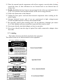
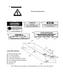
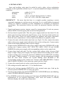
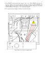
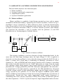
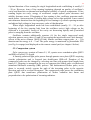
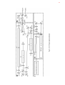
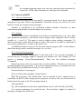
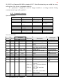
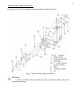
www.ekspla.com
Laser SL335
TECHNICAL DESCRIPTION
&
USER'S MANUAL
Vilnius, 2005
1
TABLE OF CONTENTS
1. STANDARD SPECIFICATION ..................................................................................... 2
2. SAFETY PRECAUTIONS........................................................................................... 3
2.1. Safety Features and Compliance to Government Requirements .................... 3
2.2. Laser radiation................................................................................................. 3
2.3. Lamplight radiation......................................................................................... 4
2.4. Back reflection safety...................................................................................... 4
2.5. Electrical safety ............................................................................................... 5
2.6. Guide for safe use of the laser system............................................................. 5
3. LIST OF CONTROLS .................................................................................................... 8
4. INSTALLATION .......................................................................................................... 11
5. LASER OPTICAL SCHEME AND PRINCIPLE OF OPERATION........................... 13
5.1. Master oscillator............................................................................................ 13
5.2. Compression system...................................................................................... 14
5.3. Amplification system .................................................................................... 16
5.4. Harmonics generation ................................................................................... 16
5.5. External triggering ........................................................................................ 17
5.6. User output signals........................................................................................ 18
6. CONTROL .................................................................................................................... 19
6.1. Remote Control Pad ...................................................................................... 19
6.2. Control via RS232......................................................................................... 24
7. OPERATION MANUAL .............................................................................................. 27
8. MAINTENANCE MANUAL....................................................................................... 28
8.1. Maintenance schedule ................................................................................. 28
8.2. Cleaning of optical components.................................................................. 28
8.3. Flash lamp replacement............................................................................... 28
8.4. Harmonics generator optimization .............................................................. 32
8.5. Primary water replacement.......................................................................... 33
8.6. Washing of cooling system ......................................................................... 33
9. TROUBLE SHOOTING GUIDE ................................................................................. 34
9.1. Fuses schedule ............................................................................................. 34
9.2. Error conditions........................................................................................... 34
10. INSTRUCTIONS FOR A SERVICEMAN................................................................. 36
10.1. Servicing regime from control pad ............................................................. 36
10.2. Adjustment of master oscillator .................................................................. 38
10.3. Adjustment of SBS compressor .................................................................. 40
10.4. Adjustment of amplification system ........................................................... 41
10.5. Replacement of Nd:YAG rods .................................................................... 41
11. COMPONENTS ............................................................................................................ 42
12. SPARE PARTS AND ACCESSORIES....................................................................... 42
13. WARRANTY STATEMENT ...................................................................................... 43
14. TESTING DATA......................................................................................................... 44
15. TECHNICAL PASSPORT .......................................................................................... 45
2
1. STANDARD SPECIFICATION
WAVELENGTH, nm
1064 / 532
PULSE DURATION, ps
150-550
JITTER, ns (Standard Deviation)
±0.5
PULSE ENERGY, mJ
500 at 1064 nm
240 at 532 nm
PULSE ENERGY STABILITY, %
(Standard Deviation)
±2.5 at 1064 nm
±7 at 532 nm
BEAM POLARIZATION
vertical at 1064 nm
horizontal at 532 nm
BEAM DIAMETER, mm
~8
BEAM MODE
TEM00, near Gaussian
BEAM DIVERGENCE, mrad
(at 1064 nm, full angle at 1/e2)
<0.5
MAX. REPETITION RATE, Hz
5
WATER CONSUMPTION, l/min
(max. 20 °C)
≤8
3
2. SAFETY PRECAUTIONS
2.1. Safety Features and Compliance to Government Requirements
This laser is a fourth class laser product according to radiation danger degree, and,
by definition, relates to certain safety and fire hazards. The following features are
incorporated into the laser to conform to several government requirements. The
applicable United States Government requirements are contained in 21 CFR, chapter 1,
subchapter J, administered by the Center for Devices and Radiological Health (CDRH).
The European Community requirements for product safety are specified in the Low
Voltage Directive (LVD) (published in73/23 EEC and amended in 93/68 EEC). The
Low Voltage Directive requires that lasers comply with the EN-60825-1 (Radiation
Safety of Laser Products) and IEC-1010-1 (Safety Requirements for Electrical
Equipment for Measurement, Control and Laboratory Use).
The laser head is enclosured in a protective housing that prevents human access to
radiation in excess of the limits of Class I radiation as specified in 21 CFR , subchapter
J, Section 1040.10(f) (1) and Table 1-A/EN60825-1, clause 4.2 except for the output
beam, which is Class IV.
The appropriately labelled light on the laser head illuminate before laser emission
can occur. Amber light is used so that it will be seen when the proper type of safety
glasses are used (21 CFR , subchapter J, Section 1040.10(f) (5) /EN60825-1, clause
4.6).
A beam shutter prevents contact with laser radiation without the need to switch off
the laser (21 CFR , subchapter J, Section 1040.10(f) (6) /EN60825-1, clause 4.7).
The laser controls are positioned so that the operator is not exposed to laser
emission while manipulating the controls (21 CFR , subchapter J, Section 1040.10(f) (7)
/EN60825-1, clause 4.8).
2.2. Laser radiation
1. The laser radiation emitted by this laser may be of different wavelengths as follows.
Fundamental radiation
Second harmonic
Third harmonic
1064 nm
532 nm
355 nm
Infra red
Visible
Ultra violet
completely invisible
visible
completely invisible
The wavelength emitted by a particular laser system is specified on the warning logo.
All reflections, whether specular or diffuse, from optical components such as steering
mirrors and prisms are dangerous. The eye will transmit most of the laser radiation
directly to the retina which can be severely damaged. If you are in doubt about the
distribution of laser radiation within external optical system, relevant detecting
equipment should be used. Damage to other parts of the body will be a function of the
laser power level and exposure time.
4
Attention:
Laser goggles/glasses of the approved type must be worn by all
personnel at all times during operation of the system. This protective
eyewear must be effective at the wavelengths that can be generated.
1. Care must be taken when using focusing optics external to the laser system. Mirrors
or lenses can reflect the beam back into the laser system. Such returned power can
damage optical surfaces or components. A He-Ne laser mounted collinear to the
optical axis can serve as a convenient check on possible reflecting surfaces.
2. The radiation classed as completely invisible may interact with any surface on which
it impinges to produce visible light. The user is warned that even this light may be
hazardous and that he or she should maintain maximum care at all times.
3. Access to laser areas should be restricted to personnel whose work requires operation
of the laser. These personnel must be instructed in the necessary safety procedures.
Warning signs placed near the laser area are recommended.
4. The experiments are recommended to be set up in such a way that beams are not at
eye level.
5. Read and mind the specific Warning information attached to the laser system and
described in chapter 2.7 below.
#
2.3. Lamplight radiation
The very design of this laser ensures that the operator is protected from flash lamp
radiation. Namely:
a) The beam path is utterly shrouded within the laser cavity.
b) The construction of the protective housing of pump chamber with flash lamps inside
does not permit the user to get in direct contact with lamplight radiation. However,
this radiation contains UV and IR components which are hazardous to eye. Also, laser
eyewear may not filter some hazardous wavelengths.
$
Caution:
Avoid viewing close to laser apertures. It is essential to use protective
goggles when handling flash lamps.
2.4. Back reflection safety
The back reflections from filter plates, prisms et al may form additional resonator
with uncontrollable radiation profiles.
High energy radiation focused inside the laser resonator may cause severe damage
of optical elements: both on surfaces and in bulk.
Optical parts in the laser such as harmonic generator and output mirrors are
vulnerable to severe damage if a small percentage of the output laser beam is reflected
and focused back into the laser. For instance, a common, uncoated, positive, simple lens
will reflect about 4% of the beam at each surface. The first surface reflection will
diverge in the backward direction, but the second surface reflection will focus and at
the focus the intensity will be very high, often enough to cause optical damage.
Even surfaces with anti-reflection coatings may back reflect focused energy enough to
cause damage.
5
To avoid this hazard, minimize focused back reflections direct them off-axis to a
harmless area or into an energy trap. Damage due to back reflections is not covered by
any EKSPLA warranty.
2.5. Electrical safety
When the equipment is operated with all safety covers in place, then operating the
controls available on the units in power supply Cabinet does not present the operator
with an electrical hazard.
The equipment must not be operated with any covers removed and/or interlocks
by-passed or defeated.
Only competent personnel must be allowed access to the equipment.
BEFORE REMOVING ANY COVERS OR PANELS:
a) The equipment must be isolated from the mains supply elsewhere. Allow 2 minutes
to elapse from isolating the supply, to ensure that energy stored in the system has
sufficient time to dissipate.
b) Certain actions specified in the fault finding procedures require access to electrical
parts in the equipment. This work must only be carried out by a competent person
who is familiar with normal safety procedures when dealing with high voltage and
extra high voltage supplies. He must also be familiar with the equipment circuitry and
layout and follow the electrical schematics.
c) A high voltage meter that reads up to 3000 V DC and 1000 V AC must be used to
check that the circuitry that is to be worked is electrically dead. Where appropriate,
the circuitry should be shorted to ground using a shorting lead.
2.6. Guide for safe use of the laser system
1.
2.
3.
4.
Set up controlled access areas for laser operation.
Limit access to the laser to personnel which presence is necessary.
Never look directly into the laser beam.
Survey the area where the laser beam traverses and block all unnecessary specular
reflections and scattering.
5. Terminate the laser beam.
6. Avoid blocking the output beams or their reflections with any part of your body.
7. Operate the laser at the lowest beam intensity possible for a given application.
8. Wear safety goggles; choose a model consistent with use conditions and visual
function required.
9. Expand the laser beam whenever possible to reduce beam intensity.
10. Absorb secondary reflections with energy absorbing filters.
11. Work in high ambient illumination when possible. This keeps the eye's pupil
constricted, thus reducing the possibility of eye damage.
6
12. Place the external optical components with a flat or negative curved surface looking
toward the laser, so that reflections are not focused back or are directed into an
energy trap.
13. Double check that the laser beam is not generated in fact when you anticipate that it
is off. Use a positive check method such as an IR card or energy detector.
14. Follow the instructions in this Manual.
15. Unplug the laser power cord and short internal components when working on the
power supply.
16. Attempt electrical service only if you are experienced in high voltage/current
circuits and understand the circuitry and related hazards.
17. Be especially careful when working with 1.06 µm radiation. Although you cannot
see it, this radiation will pass around the corner and focus on the retina.
18. Never gaze directly into naked adapter at laser in operation.
19. Never gaze directly into the edge of optical fiber cable connected to adapter when
laser runs.
2.7. Labeling
The further listed are the labels attached to the equipment.
The further listed are the labels attached to the equipment.
A. Laser radiation warnings
Laser hazard label
Aperture label
Cover interlock label
Cover hazard label
7
B. Electrical warning
Electrical shock label
Fig.2 Illustrative positions of warning labels on SL335 series laser head
8
3. LIST OF CONTROLS
The following controls are located on the front panel of the power supply cabinet (see
Fig.3).
Fig.3. Front view of power supply Cabinet
9
• KEYSWITCH [K1] – turning the key is switching laser from standby mode to
operation mode. In operation mode power is supplied to the flash lamp power
supply, cooling unit and microcontroller.
&
Note:
In stand-by mode POWER indicator is blinking and the keyswitch is
off, indicating that power supply of harmonic temperature controllers (in which
the harmonics crystals are placed) remains turned on meanwhile the system
remains isolated from the mains. This ensures the maintenance harmonics
crystals at a stable elevated temperature and prevents them from the damage
from the moisture.
• CIRCUIT BREAKER [MS] − an emergency switch to shut down the whole system.
Depressing this mushroom head button cancels mains powering to power supplies
and cooling unit.
To revert to the normal laser operation after an emergency exit, turn the keyswitch
[K1] to position OFF and then to ON again.
• CONTROL – external trigger input (connector BNC type) controlling flash lamp
operation.
• IN – external triggering input (connector BNC type) controlling Q-switch operation.
• REMOTE – remote control pad’s connector.
• RS232 – optional RS232 interface for computer control.
On the PS5012E power supply:
• TRIGGERING ON [B1] − push-button switch with an integrated indicator,
enabling flash lamp power supply operation from either internal or external triggering
source. Illuminated when triggering is enabled.
• TRIGGERING OFF [B2] − push-button switch, disabling power supply triggering.
• AMPLIFIER ON/OFF [S1] − rocker switch, enabling/disabling laser amplifier’s
operation. In position OFF this switch stops the simmer of amplifier flash lamp.
• POWER [S2] − main switch of the power supply - rocker type switch with an
integrated indicator. Illuminated when power supply is on.
• OSCILLATOR VOLTAGE [P1] − multi-turn tuner with an integrated locking lever
enabling oscillator’s flash lamp pump level adjustment (setting the oscillator’s
capacitor bank voltage level). The capacitor bank voltage is indicated on the LED
display. Maximum voltage is 1000 V.
• AMPLIFIER VOLTAGE [P2] − multi-turn tuner with an integrated locking lever,
enabling amplifier’s flash lamp pump level adjustment (setting the amplifier's
capacitor bank voltage level). The capacitor bank voltage is indicated on the LED
display.
10
On the PS1222CO cooling unit:
• POWER [S3] − main switch of the cooling unit - rocker type switch with an
integrated indicator. Illuminated when cooling system is on.
• TEMPERATURE [P3] − multi-turn tuner with an integrated locking lever, allowing
the setting of water temperature in primary loop.
• MEASURE/SET [B3] − push-button switch, selecting the mode of the cooling unit
LED display. When depressed (SET mode) display reads the preset by the P3 primary
water temperature. Usual mode of this switch is MEASURE (released) and in this
mode cooling unit LED is indicating the actual temperature of the cooling water in
primary loop.
On the Laser Head:
• FBC – photodetector output (connector LEMO type) for oscillator operation
monitoring during maintenance and potentiometer for FBC high voltage adjustment.
11
4. INSTALLATION
Laser and auxiliary units must be settled in such a place, where exploitation
conforms to the regulations enlisted in p.2.1. of present manual and comply with below
conditions:
temperature
within 15÷25 °C;
humidity
below 85 %;
water
≤ 20 °C, at least 8 l/min (pressure 1÷8 bars);
mains
208 V AC ±10%, 50/60 Hz, single phase.
IMPORTANT!
Be aware that this laser is a complex product requiring a certain
personnel experience to conform service precisely. So, we would highly recommend
calling for EKSPLA assistance at laser installation (or assistance of authorised
serviceman). The instructions bellow are useful for personnel familiar with laser
SL335.
1. Unpack and inspect exterior injuries caused by transportation. If such are present,
inform EKSPLA and the agency that carried out transportation.
2. Fix laser head to optical table. Place the power supply stand near laser head. Fix the
plastic pipe from laser head to the stand. Remove covers from laser head and the rear
cover from stand. Check all optical mounts for tightness and proper placement.
Check all water connections to verify all quick-disconnects are properly seated.
3. Connect the units with the stand control unit (see Fig.4). For this, connect the mains
cable on the power supply stand with mains inlet on the cooling unit. Connect mains
outlet on the stand with mains inlet on power supply.
4. Connect socket INTERLOCK on the power supply with socket INTERLOCK on the
cooling unit. Connect sockets OSC. SYNC IN, AMPL. SYNC IN and LASER
EMISSION on the power supply with corresponding sockets on the control unit.
5. Connect laser head with units. For this, connect high voltage cables of power flash
lamps to high voltage power supply unit output connections according to the marks.
Connect cooling pipes to lock-nut junctions LASER IN and LASER OUT according
to the marks. Connect terminal '⊥' on power supply with the ground wire coming
from the laser head. Connect the crystals heating cable HEATER to the
corresponding socket on the control unit. Connect cable BREAKDOWN. Connect
cable LASER CONTROL to the socket on control unit (see Fig.4).
6. Connect the control pad to its socket on the front of control unit.
7. Fill cooling unit in the stand with ~3.5 l of distilled water.
8. Link up the lock-nut junction WATER IN to the external water pipe. Link up the
lock-nut junction WATER OFF to water pipe gutter.
9. Turn key-turn switch to the position POWER ON. LED POWER must start blinking,
while LED BREAKDOWN remains unlit.
10. Turn POWER switch in the cooling unit. Push button TEMPERATURE SET and use
potentiometer to set required temperature value. After the button is released,
indicator displays the actual water temperature.
12
11. Turn POWER switch in the power supply. After 1 sec, LEDs ERROR must die out.
In 4 sec, simmers turn on and capacitors batteries get charged. LEDs SIMMER and
READY light. Set specified oscillator and amplifier voltages. Then press the button
TRIGGERING ON for some 1÷2 sec. It must get lighted.
12. Use control pad (see chapter 6 further) to operate the laser.
Fig.4. Rear view of power supply stand
13
5. LASER OPTICAL SCHEME AND PRINCIPLE OF OPERATION
The laser head comprises four functional parts:
• Master oscillator
• System of optical pulse compression
• Amplification system
• System of harmonics generation
5.1. Master oscillator
Master oscillator is a module of rigid design mounted on invar rods to ensure
mechanical and thermal stability. Optical layout of master oscillator is shown in Fig.5.
Oscillator’s cavity is formed by a 100% reflectivity mirror (1) and an uncoated glass
Fabry-Perrot etalon (9) for the longitudinal mode selection. Part of the electrooptical
Q-switch (2) between electrodes a and b is used as classical Q-switch, while another
part (between the electrodes c and b) together with the polarizer (3) and PIN
photodetector are forming negative feedback system.
1
2
a
b
3
4
5
6
7
8
9
c
HVC1
PIN
HV
supply
FBC
Fig.5. Scheme of master oscillator
This negative feedback is used for selection of single longitudinal mode. At the
same time the flash lamp discharge starts, the high voltage (~3 kV) is applied to
electrode a to close the oscillator’s cavity when the energy stored in the Nd:YAG rod is
below a certain level. Flash lamp is continuing its discharge (excitation of active
element) for ~100 µs (FWHM) and when energy stored in active element is exceeding
that certain level that Q-switch can not “hold”, light starts to escape from the cavity
(free running). When lasing appears, part of light reflected by polarizer (3) hits PIN
photodetector. Voltage generated by the FBC electronics and applied to the electrode c
is proportional to the light intensity registered by the PIN photodetector. Increased
electrode voltage results in light polarization change and the bigger portion of light
energy rejected by the polarizer (3). In result the negative feedback system allows
master oscillator to keep lasing at certain low level for prolonged time (several tens of
microseconds). During this time single longitudinal mode (single frequency) is
establishing due to the selective properties of Fabry-Perot etalon (9) and lower gain for
the other frequencies. YAG:Cr crystal (4) improves single longitudinal mode selection.
14
Optimal duration of free running for single longitudinal mode establishing is usually 15
– 20 µs. However, time of free running beginning depends on quality of oscillator's
cavity and therefore on thermal and mechanical stability of optical components. If free
running begins too early, energy of oscillator's output optical pulse decreases and
stability becomes worse. If beginning of free running is late, oscillator generates multimode pulses. Autocorrection of closing high voltage solves that problem. Laser control
unit measures duration from the beginning of free running to Q-switch opening moment
and adjusts high voltage to keep necessary value of that duration.
When single longitudinal mode has been established (usually 15 – 20 µs after
beginning of the free running leak from the oscillator cavity) high voltage on the
electrode a is grounded. Losses of the cavity are decreasing rapidly and Q-switched
pulse is emerging from the oscillator.
Oscillator contains additionally aperture (6) for the single transversal mode
selection, quarter wave plates (5) and (8) preventing the interference and “hole burning”
effects in the active element (Nd:YAG rod). Master oscillator output pulse is ~ 3 ns
duration and its energy is 4 – 5 mJ. The pulse energy is monitored by photodiode PD1
(see Fig.6 overpage) and displayed on the remote control pad (see chapter 6 below).
5.2. Compression system
Pulse compressor consists of lenses L1, L2, quarter wave retardation plate QWP1
and SBS-cell with CCl4 liquid.
A linearly polarized light pulse passes through quarter wave plate QWP1 acquiring
circular polarization and is focused into double-pass SBS-cell. Duration of the
compressed pulse can be changed by selecting one lens with proper focal length from
lenses L2. Focusing is arranged in the way to compress the Stokes pulse via backward
stimulated Brillouin scattering (SBS) process. The backscattered Stokes pulse, as its
phase is reversed, strictly repeats the path of the incoming pulse in the opposite
direction and with a reversal divergence. The compressed pulse passes the retardation
plate QWP1 that transforms polarization of Stokes radiation into linear and
perpendicular to the polarization of incoming radiation.
15
16
5.3. Amplification system
Power amplifier is based on two laser chambers containing Nd:YAG rods pumped
by flash lamps and include optical components arranging two passes through the active
elements and their holders.
Laser pulses from the master oscillator are reflected by the polarizer P2 and are
amplified in Nd:YAG rod R1. The beam polarization is rotated by 90° during two passes
through the quarter wave plate QWP2. On the return pass, the amplified pulses with
rotated polarization pass the P2 and are directed by mirrors M4-M7 to the second
double-pass amplifier R2.
Amplified laser pulses pass the spatial filter consisting of lenses L5, L6 and
pinhole in the vacuum cell VC and get into the harmonic generation part.
5.4. Harmonics generation
The Nd:YAG laser fundamental wavelength can be frequency doubled, tripled and
quadrupled inserting into the beam pass the nonlinear crystals generating corresponding
harmonics. The wavelengths available are as follows:
1064 nm
(Fundamental)
Infra red
532 nm
(2nd Harmonic)
Green
The second harmonic (SH) is generated in nonlinear crystal. The SH radiation
propagates together with the fundamental beam. The harmonic conversion efficiency
should be optimized tuning the harmonic crystal for the “phase matching” where the
refractive indices of the fundamental and harmonic wavelength are equal (so called
momentum conservation rule). The SHG crystal holder is equipped by the tuning knobs
for phase matching adjustment. Phase matching angle is also dependent upon the crystal
temperature. The SHG crystal is mounted in temperature-controlled heater and kept at
the stable temperature. The heater should be turned on at all times, even when the
system is in a stand-by mode (power key-switch [K1] on the Cabinet is off) in order to
protect harmonic crystal against the atmospheric humidity. Heater is equipped with LED
indicator which commence fading and illuminating in a periodical manner, when crystal
temperature has reached the set value.
The fundamental and harmonics pulses are separated by dichroic mirrors.
17
5.5. External triggering
The laser can be triggered by external synchropulses. There are three modes of
external triggering. One of three modes can be chosen from remote control pad’s
Triggering menu (see chapter 6.1).
In mode SYNC EX1 triggering pulses must be
applied to the sockets CONTROL and IN (Fig.7).
The pulse CONTROL initiates oscillator’s and
amplifier’s pump lamps flashes and high voltage
pulse applying to the Q-switch crystal.
Synchropulse applied to the input IN controls
electrooptics. At the time moment t2 high voltage
pulse is terminated and Q-switched pulse is
generated.
In mode SYNC EX2 output sync pulse from
the outputs OUT (see chapter 5.6) can start your
experiment and after some definite time triggering
pulse from the external generator, supplied to the
input IN, starts a laser pulse generation. The delay
between OUT sync pulse and the Q-switching
(moment t2 in Fig.7) in control pad’s Delay menu
(see chapter 10.1) must be set negative and equal to
the pulse delay in external circuits between output
OUT and input IN.
Fig.7. SL335 timing charts
In mode SYNC EX3 laser generates optical pulse after every positive triggering
pulse applied to the input CONTROL. Delay between triggering pulse and optical pulse
is 1.5 ms, jitter ± 125 ns. No triggering pulses can be applied to the input IN in that
mode.
&
Note:
The laser is adjusted for 5 Hz repetition rate operation so in SYNC EX3
mode divergence of output beam is not specified if repetition rate of
triggering pulses differs from 5 Hz.
The external triggering pulses should satisfy the following conditions:
− ‘IN’, ‘CONTROL’ inputs resistance 50 Ω
− amplitude @ 50 Ω > 3.5 V (nominal 5V)
− recommended IN and CONTROL pulses duration ~10 µs
18
5.6. User output signals
One output sync pulse is available on the front panel of the power supply cabinet in
the internal triggering mode:
OUT
– BNC type socket provides sync pulse linked with the Q-switch timing
and delay controllable from the remote control pad. Pulse parameters
are as follows:
– amplitude
>4 V @ 50 Ω,
– rise time
50 ns,
– duration
>120 µs,
– jitter in respect to optical pulse: ±0.5 ns.
The delay between the Q-switching (moment t2 in Fig.7) and OUT sync pulse can
be adjusted in a range ±8 ms laser operating in internal triggering and external SYNC
EX2 modes and from +8 to –1 ms operating in external triggering modes SYNC EX1,
SYNC EX3 (see chapter 10.1 Delay menu).
OUT delay menu accessed, you see:
DL - XXXXX
Here XXXX − the delay in the units of 125 ns.
"-" sign appears when OUT sync pulse precedes the Q-switching moment (moment
t2 in Fig.7).
You can change the delay - by buttons ∆ or ∇. To log the modified delay value
into NVRAM, press the button SEL two times. Remote control pad display will read
“DONE”.
The signal of negative feedback (FBC) is accessible from connector FBC at the
right side of laser frame (see the chapter ‘10.2. Adjustment of master oscillator’ for
details).
19
6. CONTROL
6.1. Remote Control Pad
The control pad provides access to perform the following
functions:
• START/STOP optical pulsing
• Set the AMPLIFICATION level
• Set the optical pulses REPETITION RATE
• Set the SINGLE SHOTS mode
• Check output energy
Fig.8 Remote control pad
Description of commands
The main (top) part of Menu tree is depicted further.
To select main menu commands (this corresponds to a vertical movement in
scheme shown on Fig.8), press button SEL and hold it down while selecting the desired
command by buttons ∆ and ∇. When selected, release the button SEL. Remote control
pad display will show one of the sub-menu commands. To select another command, use
button SEL to move in a sub-menu.
20
Home menu
When in Home menu, display shows two different strings in dependence of laser
status. If laser is operating:
or
XX
Æ
YYYm
X X ~ Y Y Y m or
XX
Æ
YYYm
XX ~ YYYm
and in case laser is paused:
Here:
XX YYY -
amplification level;
readings of energy meter.
If amplification is switched off the digits of amplification level are blinking.
The mark '~' is displayed when laser is operating from internal synchronization; the
arrow mark shows that synchronization is external.
You can:
• start/stop laser operation - by pressing button OP (in external triggering mode it stops
laser generating only, but not lamps flashing);
• switch amplification on/off - by simultaneous pressing of buttons ∆ and ∇;
• change amplification level - by buttons ∆ and ∇.
&
Note:
In external triggering mode you can only start/stop laser operation
by button OP. All the other functions of control pad are forbidden.
Single-shots menu
This menu provides access to control the laser generation. The generation may be
turned on for 1 through 99 lamps' flashes, thus resulting in a packet of laser pulses.
After a set number of shots are fired, generation is turned off again and lamps proceed
flashing idly. In this way, a fixed number of shots can be fired to the target.
When in Single-shots menu, display looks like:
P k
Here:
XX
XX - number of pulses in a packet;
In the course of generation of pulses packet, the view of display is that below:
L f
Here:
nn
n n
- number of pulses remaining;
You can:
• change size of pulses packet - by buttons ∆ and ∇;
• give start for pulses packet - by button SEL;
• start/stop laser operation - by pressing button OP.
21
NOTES.
1. Pressing of button SEL does not start/stop the laser flashing, it only affects the optical
pulses generation. Therefore, pressing of SEL will not force the laser out of the
temporal halting.
2. If at laser paused press buttons SEL and OP in a sequence, after 70 idle flashes a
packet of pulses will be fired, and then the laser resumes flashing without generation.
3. If press SEL while laser is in the process of generating pulses, generation will be
turned off after fixed packet of pulses has been generated.
Regime menu
There are five regimes available:
• Regime 0 is allotted for routine maintenance;
• Regime 1 & 2 allows changing/programming of laser pulse repetition rate and
maximal amplification level;
• Regimes 8 & 9 are for laser servicing only.
The latter laser servicing regime features expanded main menu (see chapter 8.1)
and allows operating the laser with covers open.
Regimes 0, 2 & 1 as well as 8 & 9 differ only by indications of energy meters. In
regimeses 0, 2 and 8, a measured 1064 nm wavelength energy is presented at 'Home
Menu'. In modes 1 and 9, energy at master oscillator is measured and 'Home Menu'
looks like:
XX ~ Y . YY
Here Y.YY − the measured energy, in mJ.
NOTE!
Switch off the amplifier when measuring output energy of the master
oscillator. Measurement with working amplifier gives an incorrect result.
When in Regime menu, display looks like:
R e g i me
X
Here XX - regime number.
The regime number is changeable by buttons ∆ and ∇. After switching on, laser is
always in default regime 0.
IMPORTANT! Customer is not sanctioned to operate the laser in the regimes 8 or 9.
22
When Regime 2 is set, access to the commands pictured below is provided:
Amplification limit menu
As maximum laser output energy is not necessary in every particular event of
operation, a possibility is foreseen to limit it up to a certain level.
Amplification limit menu accessed, display looks like:
Ma x E XX
Here XX - maximum amplification level you have chosen, ie the topmost number
to which you will be allowed to rise amplification level when in Home menu.
You can:
• change maximum amplification level in the range of 1 ... 99 - by buttons ∆ and ∇;
• log the chosen amplification limit into NVRAM, to retain it after laser power is
switched off - by button SEL; to log, SEL must be pressed twice;
• start/stop laser operation - by pressing button OP.
23
Frequency divider menu
Laser pulse repetition rate of 5 Hz is not always necessary, it may be reduced 2 to
10 times, while the frequency of pump lamps flashes remains unchanged 5 Hz.
Frequency divider menu accessed, display looks like:
F
D i v
XX
Here XX - division factor - number from 1 to 10.
Eg, XX=1 gives 5 Hz pulse repetition rate, XX=5 does 1 Hz.
You can:
• change pulse repetition rate - by buttons ∆ and ∇;
• log the chosen division factor into NVRAM, to retain it after laser power is switched
off - by button SEL; to log, SEL must be pressed twice.
Feedback time menu
Feedback time menu is the following:
∆=XXX
YY → s t a b
Z → W r i t e
∆ t → Do n e
W r t
Here:
XX is the measured streatching time
YY is the desired value of feedback action time or '− −' in case autocorrection is OFF.
Z is stabilisation parameter (inertness of autoadjustment) 2..9 or '− −' in case
autocorrection is OFF.
- To switch autocorrection ON / OFF press buttons "∆" and "∇" together.
- YY and Z changeable by "∆" and "∇" at the corresponding submenu.
- After pressing "SEL" at submenu W r i t e ∆ t , parameters YY and Z are
saved in NVRAM.
- Feedback action time is stabilised by adjusting high voltage (at high voltage menu).
DAC controller allows to change voltage within a narrow diapazone, therefore, at the
edge of DAC values diapazone, the following indication is displayed:
LO PUMP or HI PUMP , which indicate the voltage is too low or too high;
DAC bias requires correction (potentiometer at laser frame).
- In case the lowest DAC value is achieved (indication 'LO PUMP' displayed), laser
shooting is stopped.
Triggering menu
In this menu, external or internal synchronization mode can be chosen.
Having entered this menu, control pad indicates 'SYNC INT' if the laser is operated
from internal generator. Indications 'SYNC EX1', 'SYNC EX2' and 'SYNC EX3' mean
three different modes of external triggering (see chapter 5.5 External triggering). The
mode might be chosen by buttons '∆' and '∆'.
Synchronization mode is saved by pressing 'SEL' button until indication 'Done Wr'
appears.
24
&
Note:
In external triggering mode you can only start/stop laser operation by
button OP. All the other functions of control pad are forbidden.
6.2. Control via RS232
6.2.1. General information
Communication between devices and PC is message-based. Every device can send
messages at any time. There is no handshake. Therefore, devices, as well as PC, have
buffers to keep raw (unprocessed) messages.
Transfer is considered to be performed without mistakes, therefore, no data
confirmation and mistake control messages are necessary.
6.2.2. Names
As RS232 port allows controlling several devices simultaneously (e.g., laser, data
unit, parametric generator), each device owns a unique name composed of two or three
symbols A... z and 0..9. The name is used as address when sending commands. To
answer a message, sender must also have a name. The name of a sender is composed of
two or three symbols too. A name of the laser is SL.
An additional name is reserved for the main control program: MS. At this address,
data from energy meters, mistake messages, etc. are sent.
6.2.3. General message form
Every message starts with symbol '[' and ends with ']'. In a system consisting of
several devices, a message might be inserted into another one. For example, PC can
receive a message '[Com[Command]mand]'. There are two uniform messages
'Command'.
Receiving device does not repeat the received symbols. Therefore, in case any
terminal program (Hyperterminal...) is used for manual operation, you should switch on
the option'echo typed characters locally' to view symbols.
General format of a message is:
[ReceiverName:MessageBody \SenderNaime]
Both 'ReceiverName' and 'SenderName' can be omitted if only a single device is
controlled via RS232 with a single process program. In such a case, you do not need to
bother about the name at all. The message format is:
[MessageBodyl
E.g., the command to set the laser amplification level 50 will look like [EO/S50].
In a system consisting of several devices, 'ReceiverNanie' might be omitted if
message is assigned for all devices.
25
6.2.4. Message body form
A message might contain one or several commands. Commands are divided by
space symbol. General (total) length of a message cannot exceed 127 symbols including
addresses and symbols [ ]. Message exceeding 127 symbols is ignored.
Device does not decode an incoming message before terminator received.
Commands are executed in the order they are transmitted.
6.2.5. Command form
Two types of commands are available: system command and general command.
1. System command
A system command is a single word composed from symbols A...z and 0…9. A
system command might be with a parameter or without it. Parameter is separated from a
command by symbol = or closed within inverted commas. For example, [NAME=D1]
and [NAME"D1"] are the same commands NAME with parameter DI. In case symbols "
" are used, symbols / \ [ ] = : and space symbol are restricted for parameter. In case
symbol = is used, symbols \ [ ] are restricted for parameter and a message should
contain only a single command.
Several commands are common for all devices:
SAY - the most harmless command. It does nothing. An answer is READY or
BUSY. The command is used to check what devices are on line. A device sends
message BUSY when some operations are being executed, e.g., start up operation.
RESET - forces a device to repeat start up procedures. Having finished them, the
device sends READY. In this case, READY means the device is ready to receive
commands but not the absence of problems. In a case of mistake, additional messages
might be sent between RESET and READY. These messages are described in the
commands summary.
PowerON - device sends after connection to mains
READY - device sends in case it is ready to execute commands.
2. General command.
General commands are used to control device sub-sections. Device sub-section
is a one- dimension array of numbers or string constants. Elements of array might be
read, written, increased or decreased. To explain syntax, the following example is given
(a command to set laser amplification level 50):
EO/S50
Here E - the array name, it might be a single letter A...z.
0 - index, this is a word type number 0...65535.
/ - separator.
S - action key. Might be the following: S A P ?. The key S (SET) writes the
parameter. The key A (ADD) increases or decreases the parameter. The key P
(PROGRAM) makes the parameter NONVOLATILE. Used in devices where constants
are saved in EEPROM. Symbol ? indicates the inquiry. The device replies to this
inquiry by the answer of the same syntax. E.g., in case the amplification level is set to
26
50, SL321 will answer EO/S50 to inquiry EO/?. Not all actions keys are valid for every
sub-section. See device command summary.
50 - parameter. It might be a real or integer number or a. string constant. String
constant must begin with symbol =.
6.2.6. Commands summary
System commands:
Sender
PC
PC
PC
Command
VER
SN
START
PC
PC
PC
PC
PC
Device
STOP
SAY
NAME
RESET
PACK
Power ON
Response
VER=string
SN=string
STARE=int
Description
1 - control board
2 - cover
General commands:
E0
P0
D0
SA?
SA?
SA?P
Parameter
type
bounds
int.
1...C4
int.
1…100
int.
1…100
D1
SA?P
int.
400…2000
D2
F0
SA?P
SA?P
int.
int.
-3200..3200
1…10
C0
C1
C2
C3
C4
SA?P
SA?P
SA?P
SA?P
SA?P
int.
int.
int.
int.
int.
1…1000
1…1000
1…1000
1…1000
1…99
C5
SA?
int.
1…15
Array
Keys
Response
Amplification level
Oscillator - amplifier
delay
Delay between OSC
lamp flash and EO signal
SYNC OUT
Repetition rate divider
MaA
MaO
KoA
KoO
MaxE
[E1/S int]
[E2/S real]
[T0/S int]
[U0/S int]
C6
C7
S?
S?
int.
int.
0…1
0…1
Description: int – integer
Description
bit1 – Amplifier EM data
transmit
bit2 – Oscillator EM data
transmit
bit3 - FBC time data
transmit
bit4 - FBC control DAC
data transmit
EO ON/OFF
Amplification ON/OFF
Control pad
menu item
Home menu
Single-shots menu
Delay menu
Delay menu
OUT delay menu
Frequency divider
menu
Programme menu
Programme menu
Programme menu
Programme menu
Amplification limit
menu
Electrooptics menu
27
7. OPERATION MANUAL
1. Turning laser on
• Turn key-switch on power supply cabinet to the position POWER ON. Wait until
LEDs READY on the lamp power supply light, and depress the button
TRIGGERING ON for 1 – 2 sec.
• Open external cooling water supply line.
• Allow the laser to warm up. Laser will be operating in a stable way when water
temperature in the primary loop will reach preset value. Laser is ready for operation,
• Use remote control pad to operate the laser. Refer to Chapter 6 for commands.
2. Turning laser off
Turn key-switch to the position POWER OFF. LED POWER will be blinking
indicating that laser is in stand by mode and there is power supplied to the harmonic
heaters.
3. Temporal halting of laser operation
If you plan to revert to operate the laser after a short pause (up to, say, some half an
hour), it is recommended to stop the laser by pressing button OP on the remote
control pad, thus leaving power on. In this case the laser thermal conditions will be
retained, and after a pause laser will return quickly to the same operation mode as it
was before stopping.
4. Changing a pulse duration
• Stop the laser by pressing button OP on the remote control pad.
• Open the laser head cover.
• Turn the disc with lenses to necessary position. The lens with marked appropriate
duration should be moved to the beam path in front of SBS cell input.
• Close the cover.
• Run the laser by pressing button OP on the remote control pad.
28
8. MAINTENANCE MANUAL
To perform laser maintenance procedures the following devices and materials are
required:
• Oscilloscope with bandwith 100 MHz or more,
• 50 Ω terminal,
• Lens cleaning tissue,
• Pure ethanol (for the cleaning of optical components),
• Visualizer or IR wiever,
• Power meter.
8.1.
Maintenance schedule
Weekly, Monthly:
• inspect cleanness of all the optical components surfaces;
• check for any water leaks external to the Cabinet;
• check all external hose connections for damage or loosening.
Every three months:
• all the above;
• change the primary water
Every six months:
• all the above;
• inspect flash lamps and replace them if necessary
Every year:
• all the above
• replace the deionizer and particle filter cartridges.
8.2.
Cleaning of optical components
1. Inspect the surface of optical components carefully. Dust particles sticking or buildup of films on optical surfaces may cause costly damage of optical components.
2. Contaminated optical surfaces may be cleaned by air-brush (Be sure that your airbrush is clean!).
3. If dust or other contaminants are not removed when using air brush, use lens
cleaning tissue moistened with pure alcohol (eg ethanol, methanol et al). Purity of
solvent must be checked beforehand: put a drop of alcohol on a glass plate and after
solvent evaporates, none marks must be left on the glass surface.
CAUTION! The all harmonic crystals are highly hygroscopic and must be cleansed
exceptionally with squirrel-tail brush, or dust may be blown out by air
stream. When this does not help use water-free pure butylacetat.
8.3.
Flash lamp replacement
29
Amplifier flash lamp replacement:
Layout of SL335 laser amplifier pump chamber is shown in Fig.9.
Fig.9. Layout of laser pump chamber
%
Warning:
Failure to follow this procedure precisely can lead to injury and severe
equipment damage.
30
1. Make sure the laser system is switched off and isolated from mains supply.
2. Allow at least two minutes to elapse since the flash lamps were powered the last
time.
3. Remove the main laser head cover.
Caution:
Always wear safety goggles to protect the eyes from flying debris, should
the flash lamp explode whilst handling.
4. From both sides of pump chamber, release the screws fixing the lamp end caps
(see Fig.9).
5. Carefully, slightly rotating to and fro around the lamp axis, take the caps off.
$
&
Note:
Do not make any bending movements nor apply strength –
otherwise, the lamp can break.
6. By 3−4 full cycles, release the screws fixing the lamp pressure plates .
7. Moving to and from around its axis slightly, pull the lamp out of the pump chamber.
If the lamp does not move easily, loosen the screws a bit more.
8. Some water can drain from the pump chamber. Wipe this water and dry the area
carefully, in particular around the rod pressure plate.
9. Cleanse the new flash lamp with methanole or acetone. At further handling, hold it
only at the metallic electrodes.
10. Place this lamp into pump chamber. Lamp endings of roughly equal length should
protrude from both sides of pump chamber.
#
Attention:
Take special care to orient the lamp properly: its anode (marked with
red paint) must reside at the -marked end of the pump chamber.
Remember: the red-painted flash lamp lead is positive and the black-painted is
negative.
11. Tighten the screws . The screws on the same side must be scrolled in turns, ie one
screw by some 1−2 cycles, then the other that much. Repeat till the screws are
tightened completely.
12. With care, keeping rotating gently, put the caps on. Make sure that the caps fit
finely on the lamp leads and none split is left between lamp caps and lamp
pressure plates .
13. Tighten the screws fixing the lamp end caps.
14. Check if water does not leak over the lamp pressure plates. Make sure the power
supply is off. Then switch the mains power to the Cabinet in whole. Turn the keyswitch [K1] (Fig.3) to position ON. Switch on the cooling unit.
15. Watch if any trails of water appear around the lamp ends.
16. In case a leakage is detected, switch off the cooling unit and the whole system.
Isolate the system from mains. Following the procedure above, take off the lamp cap
and lamp pressure plate at the leaking side of lamp chamber. Check if the O-ring is
31
seated properly. Take the O-ring out and inspect for cracks. Unless any defects, put
the O-ring back. Place and fix lamp pressure plate and lamp cap. Wipe the drained
water out.
17. If water does not leak, the power supply can be switched on.
18. If other optical components hinder to freely remove lamp caps and withdraw the
lamp, release two screws and take out the plate holding the pump chamber.
Lift the whole chamber as far as the cables and hoses allow.
19. Replace the lamp/lamps.
20. Put the pump chamber onto its holder. The directing pins on the desk must fit into
pits in the sole of pump chamber. Tighten the plate . None extra adjustments of
the chamber are needed.
Oscillator flash lamp replacement:
1. Make sure the laser system is switched off and isolated from mains supply.
2. Allow at least two minutes to elapse since the flash lamps were powered the last
time.
3. Remove the main laser head cover and one side cover to ease access to the
oscillator’s chamber.
4. Release the screw (1), unscrew (2) and remove the fixing plate (see Fig.10).
Fig.10 Pump chamber of master oscillator
5. Release screws (3) and disconnect flexible lamp electrodes (4) from connectors.
6. Carefully lift the chamber from it’s place and turn it aside to prevent water drops
falling onto optical components when removing flash lamp. It’s recommended to
close optical components by plastic film to protect them from water.
Caution:
Always wear safety goggles to protect the eyes from flying debris, should
the flash lamp explode whilst handling.
7. By 3−4 full cycles, release the screws (5) fixing the lamp pressure plates from both
sides of pump chamber.
$
32
8. Moving to and from around its axis slightly, pull the lamp out of the pump chamber
in the direction of the positive electrode. If the lamp does not move easily, loosen the
screws (5) a bit more.
9. Some water can drain from the pump chamber. Wipe this water and dry the area
carefully, in particular around the rod pressure plate.
10. Cleanse the new flash lamp with methanole or acetone. At further handling, hold it
only at the metallic electrodes.
11. Remove isolator (6) from the old flash lamp and put it on the new lamp’s electrode.
12. Place this lamp into pump chamber. The isolator (6) should lean against the lamp
pressure plate.
#
Attention:
Take special care to orient the lamp properly: its anode (red) must
reside at the -marked end of the pump chamber.
13. Tighten the screws (5). The screws on the same side must be scrolled in turns, ie one
screw by some 1−2 cycles, then the other that much. Repeat till the screws are
tightened completely.
14. Check if water does not leak over the lamp pressure plates. Make sure the power
supply is off. Then switch the mains power to the Cabinet in whole. Turn the keyswitch [K1] (Fig.3) to position ON. Switch on the cooling unit.
15. Watch if any trails of water appear around the lamp ends.
16. In case a leakage is detected, switch off the cooling unit and the whole system.
Isolate the system from mains. Following the procedure above, take off the lamp
pressure plate at the leaking side of lamp chamber. Check if the O-ring is seated
properly. Take the O-ring out and inspect for cracks. Unless any defects, put the Oring back. Place and fix lamp pressure plate and lamp cap. Wipe the drained water
out.
17. If water does not leak, put the pump chamber into its place. The directing pins on the
desk must fit into pits in the sole of pump chamber. Tighten the fixing plate by crews
(2) and then tighten (1). None extra adjustments of the chamber are needed.
8.4.
Harmonics generator optimization
While adjusting the harmonics crystals, make sure that reflections from the crystals are
directed away from the amplification system. Reflections into the amplification system
can provoke free-running generation within the system.
The harmonics crystals must be inserted and removed from the laser only when
laser operation is cancelled.
Optimize the phase-matching angle to achieve maximum SH pulse energy by adjusting
the SHG crystal in the horizontal plane. Only tune the SH crystal in the horizontal
plane; the SHG crystal is configured at the factory to prevent reflected radiation from
getting into the amplifier aperture.
33
8.5.
&
Primary water replacement
Note:
Here is a brief description; consult the Manual of cooling unit PS1222CO for
details.
1. Pulling forwards, withdraw the cooling unit from Cabinet and remove the reservoir
cork. By either siphon or stirrup-pump type device, drain the water from primary
cooling contour into a suitable vessel. Refill the reservoir with distilled water
(3.5 liters).
2. Inspect if the filter is not clogged. Replace it if necessary.
3. It is essential that none air be left in the primary circuit after the reservoir refill. To
remove the air, turn the key [K1] and power [S3] switches to ON (Fig.3). Press
button MEASURE/SET [B3], disabling all the blockings in the cooling unit. This
should cause all air in cooling contour to be pumped off into the reservoir. In the
case this did not help to remove air from pump, switch off power switch [S3], turn,
by several rounds, the filter sump to let the air out of the internal contour. Turn the
filter sump tightly again. When all the air is likely to have been removed, release the
[B3] and check primary water level. Switch off the cooling unit ([S3] to OFF). Stuff
the reservoir cork back and slide the unit into its place in the Cabinet.
8.6.
Washing of cooling system
In case you find the cooling unit infected with organic substance (kind of algae),
the whole cooling system needs to be washed over. You will need:
• 0.5 liter of 30% hydrogen peroxide or 0.5−1 litre of cleaning liquid
Extran MA-03 phosphate-free (of Merck make);
• 3.5 liter of distilled water;
• a spare particle filter;
• a spare DI filter.
1. Turn the laser system off.
2. Drain the water from cooling unit.
3. Fill the reservoir with distilled water adding the hydrogen peroxide or Extran.
4. Switch the cooling unit on. In dependence of the cleaning agent being used, leave the
unit working: for an hour in case of hydrogen peroxide and for some 3−5 min in case
of Extran.
5. Switch the unit off and drain its reservoir.
6. Replace the DI and particle filters with new.
7. Refill the reservoir with distilled water.
8. Switch the cooling unit on and make sure it works normally
&
Note.
The temperature of cooling water in the cooling unit is pre-defined at ∼29°C. If the
environmental temperature of your working place exceeds mentioned 29°C, the
laser heads may start covering with dew. Therefore, the cooling water temperature
needs to be. The maximum admissible temperature of cooling water is 32°C.
34
9. TROUBLE SHOOTING GUIDE
9.1. Fuses schedule
Fuse quantity
Fuse type
Rear of stand control unit
1
2A
3
16 A
Rear of power supply
2
16 A
Function
For protection of all units in stand
against current and short circuit damage
Protection of the power supply against
current overload and short circuit damage
9.2. Error conditions
The laser stops:
•
In case the laser control pad indicates 'DOOR', the cover should be checked.
•
In case of indication O v O X . X X , generator energy is exceeded the
programmed value (see chapter 8). To continue the work press button SEL..
•
In case of O v A X X X m , amplifier energy has exceeded the
programmed value (see chapter 10). To continue the work press button SEL.
•
CB
t / o u t , the main processor does not receive an
In case of
answer from controller at laser frame. This might happen due to wrong
connection of laser signal buss with the stand, or due controller operation
disturbance caused by strong electrical noise. To continue the work, you
should switch off the laser by turning the key and switch on the laser again.
•
In case the laser control pad indicates 'LOW PUMP' , the master oscillator
should be checked (see chapter 10.2).
On the Cabinet, there is one interlock status LED which illuminates when
BREAK DOWN circuit gets open.
On the PS5012E flash lamp power supply, there are several interlock status LEDs
illuminating in the following cases:
INTERLOCK −
at accident in cooling unit or when connection is absent between
sockets INTERLOCK on power supply and cooling unit (see Fig.3)
or cooling unit is off.
HV CONNECTORS − when high voltage wires are not attached or HV connectors are
loose or screws disabling HV connectors' blockings are not
tightened sufficiently.
OVERHEAT − when temperature detector mounted in the power supply detects
overheating of the unit. This occurs if either air stream is blocked, the
cooling fan fails or at high ambient temperatures.
35
NO CHARGE OSC − at accident in the module of power supply powering the
generator's flash lamp, when in 2−3 s capacitor does not get
charged. The cause may lay in short-circuit in capacitor, faulty
commuting thyristor or faulty charging unit.
NO CHARGE AMPL − at accident in the module of power supply powering the
amplifier's flash lamps. The likely causes are as in former case.
OVERVOLT OSC − when the maximum allowed voltage on charging capacitor of
generator flash lamp is exceeded by more than 50 V. Failure of
voltage-comparator circuit is the most probable reason.
OVERVOLT AMPL − when the maximum allowed voltage on charging capacitor of
amplifier flash lamps is exceeded by more than 50 V. The
likely cause is as in above case.
FLASHLAMPS − when in 10 s simmer fails to ignite in any of flash lamps powered
by the unit.
&
Note:
When any of above listed blockings has been activated, the unit operation can
be restored only after the cause of blocking activation is remedied and the unit is
switched off and on once again.
On the PS1222CO cooling unit there are several interlock status LEDs
illuminating in the following cases:
NO FLOW − when detector in the primary water circuit detects absence of water flow.
This occurs when the pump is not switched on or at its failure, or if
coolant is completely lost, or the cooling pipes are wrongly connected or
blocked (clutched).
Also, this blocking may be activated at the first cooling unit's switching
on after the primary water has been replaced. The air remaining in the
system is the cause. Switch the cooling unit off, switch on again, and
press button MEASURE/SET [B3] until all the air is out.
OVERHEAT − when temperature sensor in the primary water circuit detects
overheating. The instance of overheating is identified when temperature
in primary circuit grows up by 5°C above the value set by
potentiometer [P3] (see chapter 3 of this manual).
PURITY LOW − indicates that the conductivity of water in reservoir has increased.
36
10. INSTRUCTIONS FOR A SERVICEMAN
10.1. Servicing regime from control pad
When the laser control pad regime is set to 8 (from Regime menu), expanded
menu becomes available:
37
Electrooptics menu
From this point, you can switch the electrooptical signal on/off, ie to turn on/off
the laser generation.
The display reads:
EO
ON
- when the electrooptics is switched on;
EO
OFF
- when the electrooptics is switched off.
You can:
• control the electrooptics - by buttons ∆ and ∇;
• start/stop laser operation - by pressing button OP.
Delay menu
From this point, you can change and save permanently the delays between:
- flashes of lamps of master oscillator and amplifier;
- oscillator lamp's flash and electrooptical signal.
This menu accessed, the control pad displays D e l a y X X , and the delay (in
microseconds) between oscillator and amplifier lamps' flashes can be changed. This
enables to obtain the maximum laser output energy. Before starting to search for this
maximum, make sure that maximum amplification level (99) is set from Home menu.
After button SEL is pressed, the display changes to O - E X X
, and
delay between oscillator lamp's flash and electrooptical signal can be changed.
the
Here XX - delay value in units of 125 ns (ie, the actual delay in nanoseconds is
obtained by multiplying XX by 125 ns).
The delay between the Q-switching (moment t2 in Fig.7) and OUT sync pulse can
be adjusted in a range ±8 ms laser operating in internal triggering and external SYNC
EX2 modes and from +8 to –1 ms operating in external triggering modes SYNC EX1,
SYNC EX3.
You see:
DL - XXXXX
Here XXXX − the delay in the units of 125 ns.
"-" sign appears when OUT sync pulse precedes the electrooptics opening.
To log the modified delay values into NVRAM, press the button SEL two more
times until the following note is displayed:
DON E
WR
You can:
• change the delays - by buttons ∆ and ∇;
• log the newly set delay values into NVRAM - by button SEL;
• start/stop laser operation - by pressing button OP.
38
Programme menu
The laser control unit has an analog input linked to the photodetector. A part of
master oscillator's output radiation gets into this photodiode, and thus the energy can be
observed.
When in this menu, the display reads:
P R O G R A MM
From this point, you can change the coefficients that are used to calculate the
energy values returned onto control pad's display in Home and Single-shots menu. The
YY value is proportional to coefficient set from Programme menu KoA.
At the occurrence YY > MaA, laser is stopped, and note O v A Y Y
shows up on the control pad's display. If output energy of master oscillator exceeds
MaO, laser stops too. Control pad shows MaO energy in mJ.
You can:
• change the coefficients MaA and KoA - by buttons ∆ and ∇;
• select a certain coefficient and log its new value into NVRAM - by button SEL. To
log, press the SEL till the note D O N E P R O emerges.
As the energy measured is that of oscillator, there is no necessity to limit it. To
disable the protection against energy overflow, set the MaA and MaO above 5000.
10.2. Adjustment of master oscillator
CAUTION! Take special care not to damage optical surfaces!
1. Take off the laser cover.
2. Examine all the optical components (1−8) for cleanness and dust-absence. Take
measures to cleanse (see chapter 6.4) if soiled.
3. Detach high voltage connector HVC1 on oscillator (see Fig.11).
Fig.11 FBC board view
39
4. Switch on the laser (Regime 9) without the amplifier.
5. Switch the feedback off (FBC − OFF) by control pad.
6. Switch autocorrection OFF from control pad Feedback time menu by pressing
buttons ∆ and ∇ together.
7. Start laser generation by control pad. By increasing generator-pumping energy at the
stand, achieve free generation that might be watched with the help of visualizer.
8. Adjust the mirror 1 vertically and horizontally to make generation start at the lowest
possible voltage and the beam spatial profile to acquire the most symmetrical form.
9. Switch the power supply off.
10. Connect the connector HVC1.
11. Switch the electrooptics off by control pad (see chapter 8.1 above).
12. Switch the feedback on (FBC − ON) by control pad.
13. Set the minimum voltage of the Pockels cell using FBC regulator on the laser frame
(rotate the knob counterclockwise) and the control pad (High voltage menu).
14. Switch on the laser without the amplifier.
15. From control pad, switch the electrooptics off (EO − OFF).
16. Start the laser operation from the control pad.
17. Connect oscilloscope with laser connector FBC at the right side of laser frame.
18. By increasing the lamp pumping energy, obtain the oscillogram indicating the
feedback is functioning (Fig.12, the first diagram). The ∆t value will appear at
control pad indicating the time duration between beginning and end of generation.
Fig.12 Oscilloscope traces explaining Q-switch operation
19. Check if the beam precisely hits the PIN photodiode. Release the fixing screws and
move the FBC board along the body of master oscillator. PIN photodiode can also be
adjusted by slight bending up or down. The FBC signal amplitude should be~0.2−1
V
20. From the control pad, switch the electrooptics on (EO − ON).
40
21. A negative pulse should appear at oscillogram (Fig.12, the second diagram). A laser
pulse should also appear at generator output. We might check it by vizualizer and
generator energy indicator at control pad.
22. By changing electrooptics delay (EO − DELAY) achieve pulse energy maximum and
prelasing time ∆t≈15−20 µs.
23. Increase pumping voltage of the oscillator lamp to get the oscillator pulse energy
~4 mJ (specified in chapter 14). If ∆t exceeds 15−20 µs, increase electrooptics
voltage at Control pad High voltage menu to set ∆t within standard limits. In case the
high voltage tuning range is not enough to reach the necessary ∆t adjust high voltage
by the potentiometer FBC on the laser frame.
24. Adjust the rear mirror of the master oscillator to maximize ∆t and to get symmetrical
beam at the oscillator output.
25. Decrease the electrooptics voltage to get ∆t≈40 µs. Memorize this high voltage value
by pressing 'SEL' button until indication 'DONE WR' appears.
26. Get into Feedback time menu and switch autocorrection on by pressing buttons ∆
and ∇ together. Set the feedback time 10−15 µs. The oscillator pulse energy should
be ~4 mJ (specified in chapter 14). The flash lamp pumping voltage can be a bit
changed to get the specified pulse energy.
27. Stop the laser operation. At Control pad’s High voltage menu find high voltage value
and tuning range by pressing buttons ∆ or ∇. By potentiometer FBC on laser frame
adjust high voltage tuning range to find the working high voltage in the middle of
that range.
28. Operate the laser with the amplifier switched off and measure pulses energy stability
at the laser output. If laser pulses are not stabile enough, you can try to vary cooling
water temperature. Feedback time ∆t can also be adjusted in a range of few
microseconds for energy stability improving.
10.3. Adjustment of SBS compressor
1. Shield SBS cell’s front window.
2. Direct the beam from master oscillator through the central parts of focusing lens L1
and QWP1 plate (Fig.6).
3. Turning horizontally the plate, which holds polarizer P1, use visualizer to view
side-reflected radiation and minimize the reflection energy. Turning vertically, make
the reflected beam parallel to the basement surface. Do not attempt to adjust
QWP1 plate.
41
10.4. Adjustment of amplification system
1. Take the lens L3 out and shield the mirror M11.
2. Switch the generator on and the amplifier power supply off. By mirrors M9 and M10,
direct the beam through the center of power amplifier active crystal.
3. Rotating the handle AMPLIFIER VOLTAGE on the front panel of power supply, set
low amplification level, and switch the amplifier on.
4. Check the polarizer P2 for its proper orientation. For this, put a λ/2 retardation plate
in between polarizer P2 and mirror M10. Use infrared sensor to set the polarizer
angle to optimal, i.e. at which the amplifier input energy reaches minimum.
Achieving this, withdraw λ/2 plate and repeat the current point instructions once
again.
5. Uncover mirror M11. Keeping visualizer close to aperture A2, observe the
depolarized beam which profile is a ring shape. Adjusting mirror M11 direct the
depolarized beam so that it was symmetrically rejected by aperture A2 (the
depolarized beam ring center should coincide with the aperture center).
6. Cautiously rotating the QWP2 plate, obtain depolarized beam of minimal energy.
7. Put the telescope lens L3 in. Adjust it, to make the beam pass through the lens center
and the amplified beam after polarizer P2 to have a symmetrical profile.
10.5. Replacement of Nd:YAG rods
In case active Nd:YAG crystal of either oscillator or amplifier gets broken
through or damaged in any other way, it needs to be replaced. For this, perform the
following steps:
1. Release cooling water pipes, unlocking lock-nuts;
2. Unscrew fixing screws of plastic power cables caps and unlock power cables;
3. Take the flash lamp cavity out of the laser head;
4. Release the YAG:Nd rod pressure plates by unscrewing fasteners some 2-3 rotations,
and remove the rod;
5. Place the new rod carefully into its location;
6. Assemble the cavity in a reverse order;
7. Install flash lamp cavity precisely back into its initial place.
After the rod is replaced, check the output beam profile at medium power. If
considerable alteration is observed, readjustment of the relevant part of laser optical
scheme is needed. See chapters 8.2 and 8.4 for adjustment procedures of master
oscillator and amplification system correspondingly.
42
11. COMPONENTS
1. Laser head ..................................................................................... 1
2. Power supply stand ....................................................................... 1
2.1. Power supply PS5012E......................................................... 1
2.2. Cooling unit PS1222CO ....................................................... 1
3. Power supply cable ....................................................................... 1
4. Control pad.................................................................................... 1
5. Coaxial 50 Ω cables BNC-BNC ................................................... 4
12. SPARE PARTS AND ACCESSORIES
1. Fuses 16 A ..................................................................................... 3
2. Fuses 2.0 A .................................................................................... 2
3. Allen hex keys............................................................................... 4
4. Coaxial 50 Ω cable LEMO-BNC .................................................. 1
5. Binding clips 483.15 ..................................................................... 2
6. Binding bolts 483.01-02................................................................ 2
43
13. WARRANTY STATEMENT
EKSPLA warrants to the original purchaser that laser devices are free from
defects in parts and workmanship. EKSPLA will make any necessary repairs
or replacement of parts to remedy any defect according to the conditions
drawn up in the contract.
The foregoing warranty does not cover equipment that is damaged by
accident or improper use. EKSPLA does not assume any liability if
adaptations are made or accessories attached to the equipment that impair or
alter the normal functioning of the equipment. The limited warranty and
remedy contained in this paragraph are the only warranty and remedy
pertaining to the equipment. EKSPLA DISCLAIMS ALL OTHER
WARRANTIES, EXPRESSED OR IMPLIED, INCLUDING ANY
WARRANTY OF MERCHANTABILITY OR FITNESS FOR A
PARTICULAR PURPOSE. EKSPLA is not liable for any accidental,
consequential or other damages or costs, lost profits or inconvenience
occasioned by loss of the use of the equipment or labor expended by persons
not so authorized by EKSPLA.
We have a responsive Customer Service staff that will be pleased to help you
with any product difficulties. Please do not hesitate to contact them at
Altos Inc.
Phone:
+1 (949) 939-6292
Fax:
+1 (909) 363-8637
E-mail:
[email protected]
www.altos-inc.com