1
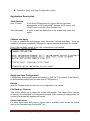
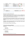
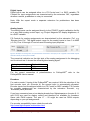
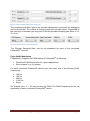
Discover the world of flight simulation www.flying-the-winglets.de Manual Version 2.0 FSSymphony is published as freeware at the moment and therefore free of charge, however copyright remains with the author. The Software may be redistributed to friends or associates. You may NOT upload the software to a freeware, shareware or any other site without first receiving written permission from the author. No parts of the Software or other files provided in this package may be reproduced in part or in whole. You may not remove any copyright or other proprietary notice from the software. You may not reverse engineer, decompile, or disassemble the software. The Software is provided "AS IS". You agree that by accepting this license, you are expressly acknowledging that the use of the software is AT YOUR OWN RISK. IN NO EVENT SHALL THE AUTHOR BE LIABLE FOR ANY DAMAGES. The use in commercial products requires the express approval of the author. © 2011 - 2014 by www.flying-the-winglets.de Page 1 Content Discover the world of flight simulation www.flying-the-winglets.de........................ 1 Manual ................................................................................................................................................... 1 General................................................................................................................................................... 4 Disclaimer .......................................................................................................................................... 4 Safety note ......................................................................................................................................... 4 Compatibility ...................................................................................................................................... 4 Constraints ......................................................................................................................................... 4 Important Note................................................................................................................................... 4 Prerequisites...................................................................................................................................... 5 Further Developments ..................................................................................................................... 5 Credits ................................................................................................................................................ 5 New Feature Version 2.0 ................................................................................................................. 5 Fixed bugs ......................................................................................................................................... 5 Improved ............................................................................................................................................ 5 PoKeys56E Supplier ........................................................................................................................ 5 SW-Installation and Initial Set-up ....................................................................................................... 7 Prerequisite: ...................................................................................................................................... 7 Backup of an existing Configuration .............................................................................................. 7 Installation Procedure ...................................................................................................................... 7 First Start of FSSymphony .................................................................................................................. 8 Prerequisite: ...................................................................................................................................... 8 Saving Configuration ........................................................................................................................ 9 Application Description ...................................................................................................................... 10 Start Options.................................................................................................................................... 10 Validate and Apply.......................................................................................................................... 10 Apply and Save Configuration ...................................................................................................... 10 Reload .............................................................................................................................................. 10 File Backup / Restore ..................................................................................................................... 10 Status Indicators ............................................................................................................................. 10 FS Controls and Extended Functions .......................................................................................... 11 Configuration of Inputs and Outputs ............................................................................................ 11 Digital Outputs ............................................................................................................................. 12 © 2011 - 2014 by www.flying-the-winglets.de Page 2 Digital Inputs ................................................................................................................................ 13 Analog Inputs............................................................................................................................... 13 Encoders ...................................................................................................................................... 13 Pulse Width Modulation ............................................................................................................. 14 Servo Example ................................................................................................................................ 15 Backlit Control Example................................................................................................................. 16 General Options .............................................................................................................................. 16 Network Transfer Protocol............................................................................................................. 17 Display Configuration ..................................................................................................................... 18 Servo Calibration Facility ............................................................................................................... 19 PoKeys Extension Bus................................................................................................................... 20 I2C Bus ............................................................................................................................................. 22 Export to EXCEL ............................................................................................................................. 25 Session Log ..................................................................................................................................... 26 B737 Goodies...................................................................................................................................... 27 B737 Flaps Position Indicator Calibration ................................................................................... 27 LE Flaps Transit and LE Flaps Extended Lights........................................................................ 28 B737 Brake Pressure Indicator..................................................................................................... 29 B737 Auto Brake Selector and Disarm Light .............................................................................. 30 B737 Backlit Control ....................................................................................................................... 31 B737 Master Dim ............................................................................................................................ 31 B737 Master LightsTest ................................................................................................................. 32 B737 Autopilot / Autothrottle Indicators on AFDS Panel .......................................................... 32 General Goodies ................................................................................................................................. 33 Generic Clock .................................................................................................................................. 33 Jet 45 Goodies .................................................................................................................................... 35 SIOC Support ...................................................................................................................................... 35 Extras.................................................................................................................................................... 37 All Light Test .................................................................................................................................... 37 Expert Mode .................................................................................................................................... 37 Overview of Supported Functions .................................................................................................... 42 Contact ................................................................................................................................................. 52 © 2011 - 2014 by www.flying-the-winglets.de Page 3 FSSymphony The program acts as smart interface between the Flight Simulator, FSUIPC and the PoKeys56E® Ethernet interface. FSSymphony V2.0 is compatible to the following flight simulators: FS2004, FSX, Prepar3D® V1.4 and V2.1. Version 2.0 supports both cockpit builders with no programming experience just by let them select the required function from a drop-down list, as well as user who want to get deeper in functionality. They can define own functions, including manipulating offsets and doing logical comparison. The program can also act as bridge to the SIOC programming language. Each of the PoKeys56E® digital inputs, outputs, analog inputs and encoders can be assigned to a SIOC variable. This gives cockpit builders a maximum of flexibility and the opportunity to interface SIOC scripts to the PoKeys56E® interface. Furthermore the PoExtBus for up to 80 additional output ports is supported and I2C bus has been introduced for 12 additional servo outputs. A variety of examples for user defined functions and comprehensive description are included in the download package. General Disclaimer Every effort has been made to ensure that the shown hardware and wiring examples are correct, however, I accept no responsibility for any errors or omissions or for any direct or consequential losses that may occur. Safety note For all hardware examples shown in this documentation it is assumed that the reader is familiar with the fundamentals of electronic circuits as well as electrical hazards and safety. Compatibility FSSymphony has been successfully tested with Microsoft® Flight Simulator 2004, Flight Simulator X, Prepar3D® V1.4 and Prepar3D® Professional V2.1. Microsoft XP®,Vista®, WINDOWS7®. 64 bit compatibility was tested with WINDOWS7®. PoKeys57E is fully compatible to PoKeys56E according to the manufacture statement. Constraints FS.Symphony supports PoKeys56E® devices. Compatibility to PoKeys56U® is not planded for the future. Important Note The configuration file of version 1.1 is not compatible to version 1.5. Form version 1.5 onwards the configuration files are backwards compatible. © 2011 - 2014 by www.flying-the-winglets.de Page 4 Prerequisites FSSymphony needs a registered copy of FSUIPC running on the PC with the FS installation. If you run FSSymphony from a remote PC than WideFS has to be installed on that PC. The Microsoft® .Net Framework 4.0 and Power Packs 10.0 have to be installed on your computer. You can get it free of charge from the Microsoft Download Center. With the FSSymphony version 1.1 and onwards the framework gets automatically installed during the setup procedure if not already available on your computer. Further Developments FSSymphony is constantly improved and further developed. If you have feature requests please drop me an email: [email protected] Credits Thanks to Peter Dowson for his great work on FSUIPC FS.Symphony uses the FSUIPC Client DLL for .NET by Paul Henty New Feature Version 2.0 - Introducing the expert mode for users who want to define their own functions - I2C status indicator Fixed bugs - B737 Light Test now includes gear indicators - Function ‘Set High State’ with the PoExtBus dialog fixed Improved - B737 Autobrake System: 3sec gate for throttle implemented PoKeys56E Supplier PoKeys56E® is distributes by FlightSimParts.eu, Belgium. For information check their website: http://www.flightsimparts.eu/Shop_Electronics_Pokeys56E.html © 2011 - 2014 by www.flying-the-winglets.de Page 5 Trademarks Microsoft Flight Simulator X and Microsoft Flight Simulator 2004, Microsoft EXCEL are registered trademarks of Microsoft Corporation in the United States and/or other countries. Microsoft XP, Microsoft Vista and Windows7 are registered trademarks of Microsoft Corporation in the United States and/or other countries. Excel is a registered trademark of Microsoft Corporation in the United States and/or other countries. PoKeys is a registered trademark of PoLabs Prepar3D is a registered trademark of Lockheed Martin Corporation © 2011 - 2014 by www.flying-the-winglets.de Page 6 SW-Installation and Initial Set-up Prerequisite: FSSymphony requires at least the firmware version 3.0.41 installed on the PoKeys56E® devices. The latest PoKeys56E® firmware can be found here: http://www.poscope.com/pokeys56e. FSSymphony requires the MICROSOFT 4.0 Framework.and and Power Packs 10.0. If the framework is not installed on your computer this will be done automatically during the set-up procedure. Make sure that an Internet connection is available for that step of the installation procedure. Backup of an existing Configuration Backup your existing configuration file prior installation of FSSymphony Version 2.0. Otherwise your configuration will get lost during the installation process. Use the ‘Export Configuration’ function of FSSymphony to perform this task. File / Export Configuration Figure 1: File Menu. From version 2.0 onwards the menu items are named ‘Backup Configuration’ and ‘Restore Configuration’ Installation Procedure Due to the reason that FSSymphony uses the .net feature ‘ClickOnce’ installation, make sure that you are logged in as the user who wants to use the application. ClickOnce-deployed applications are considered as 'low impact', in that they are installed per-user, not per-machine. No administrator privileges are required to install the application. In order to prepare the installation unzip the content of the FSSymphony V2.0 download package in a directory of your choice. Export Configuration of existing installation (if applicable) Uninstall previous version of FSSymphony with WINDOWS 'Add/Remove programs' function (if applicable) Run the setup.exe © 2011 - 2014 by www.flying-the-winglets.de Page 7 Connect your PoKeys56E® device(s) to the network Run FSSymphony from the WINDOWS Start menu FSSymphony needs some network ports for proper communication, thus your firewall might ask you for confirmation with the first usage of the program. Note: FSSymphony does not use any own port definitions, but the defined standard ports e.g. for IOCP, WideFS, and PoKeys56E® interfaces have to be enabled. Restore Configuration If you want to restore the saved configuration file open the File menu and select ‘Restore Configuration’. The imported configuration gets automatically saved. If the backup file was saved with FSSymphony prior V1.5.0 and only in this case proceed as following: Open the exported configuration file with the WINDOWS notepad Insert the following below the <Configuration> tag : <FSSymphony Version="1.1.5.0" /> The result should look like the following: <?xml version="1.0" encoding="utf-16"?> <Configuration> <FSSymphony Version="1.1.5.0" /> Save the configuration file IRestore the configuration file into FSSymphony Version 2.0 First Start of FSSymphony Prerequisite: - At least one PoKeys56E® device with fixed IP address is connected to your network. Use the PoLaps software to assign an IP address to the device. If the above condition is fulfilled then Start FSSymphony und wait for a few seconds. During the splash screen is visible FSSymphony performs a discover process on the network to find the connected PoKeys56E® devices. © 2011 - 2014 by www.flying-the-winglets.de Page 8 After this the FSSymphony main dialog appears. The devices found are listed in the ‘PoKes56E IP’ selection box. If one or more of the PoKeys56E® devices were not detected check the physical and logical network configuration. Click the button ‘Connect PoKeys’ for each of the found PoKeys56E® device The color of the ‘PoKeys Status’ indicator should change to green. FSSymphony shows additional information regarding the connected device at the top line. These are User ID, Device Serial Number, Version Major, and Minor. If the network connection to a PoKeys56E® device gets lost, FSSymphony will try to reconnect. While this process is performed, the color of the status indicator will be orange. Start the FS Flight Simulator and press the button ‘Connect FSUIPC’. With the connection established the ‘FSUIPC Status’ light turns to green. Figure 2: Main Dialog If you want to interface the PoKeys56E® device to IOCP (SIOC) then enter the IP address and the port number in the relevant fields. Start the IOCP server and press the button ‘Connect IOCP’. With a successful connection the ‘IOCP Status’ light will change color to green. Note: If the IOCP server has terminated the communication to FSSymphony, e.g. with pushing the ‘Reload’ button on the SIOC software, you have to restart FSSymphony. Saving Configuration At this point of the configuration it is a good idea to save the current settings. © 2011 - 2014 by www.flying-the-winglets.de Page 9 Press the ‘Apply and Save Configuration’ button Application Description Start Options Auto Connect If you want FSSymphony to connect with the next start automatically to the PoKeys56E® devices, IOCP server, and FSUIPC then check the ‘Auto Connect’ box Start Minimized In order to start the application in the system tray check this option Validate and Apply In order to validate the configuration press the button ‘Validate and Apply’. Once the validation has been completed FSSymphony opens Notepad and shows the results. Note: If the validation shows errors, the configuration is not applied. Figure 3: Example of a validation report Apply and Save Configuration Configuration changes get active and saved in a XML file. The content of that file will be automatically loaded with the next start of FSSymphony. Reload With the ‘Reload’ button the last but one configuration is re-called. File Backup / Restore This feature allows you to export the actual configuration. The usage of this function is strongly recommended for configuration backup. With restoring a configuration the content is automatically applied and saved. Status Indicators For each digital input and output a status light is available which shows the logical state of the corresponding PoKeys56E® pin. © 2011 - 2014 by www.flying-the-winglets.de Page 10 Figure 4: Status indications of inputs and outputs are supporting system integration and debugging For analog and encoder inputs the raw values are displayed instead of a status signal. Figure 5: For analog inputs the digital equivalent is displayed FS Controls and Extended Functions FSSymphony supports large collection of standard FS controls via FSUIPC. Thus controls are directly selectable and can be assigned to any of the PoKeys56E® I/O pins. This is by far the easiest method to hock up your flight simulator hardware to the FS without the need to deal with offsets, bits, and bytes. Moreover, FSSymphony provides extended functionalities by internal logic. Extended functionalities are for example: brake pressure indicator for B737, autobrake system for B737, flap position indicator, B737 auto brake system, and other extensive functions. FSSymphony offers direct access to functions from Project Magenta B737 GC, MCP and System, as well as TSR System B737, Jet 45. Access to other cockpit software and add-on’s will be available in future releases. For more information see chapter ‘General Options’ Configuration of Inputs and Outputs For each of the 55 PoKeys56E® I/O pins you can individually determine whether it should act as Digital Input Digital Output In addition certain pins can be used as Analog Input PWM Output Encoder Input Pins which are not used should be set to ‘Not used’. © 2011 - 2014 by www.flying-the-winglets.de Page 11 Note: Starting with FSSymphony V1.1 the Pin Assignment is automatically performed with the selection of a predefined FS Control or Extended Function. Individual selection is still possible. Note: - Due to PoKeys56E® limitations pins 5 and 6 must both set either input or output. - Pin 54 will set the PoKeys56E® device into the ‘Bootstrap’ mode, in case that this pin is connected to ‘GND’ with power on. For that reason you should use pin 54 either as output or as input for a push button but never as input for a switch which could be closed during power on sequence. Digital Outputs Digital outputs can be assigned either to FS Control or a SIOC variable. FS Controls for output assignments are characterized either by the extension ‘LIGHT’ or ‘Gate’. Figure 6: Sample of input and output assignments Digital outputs, labeled with ‘Light’ can be blanked with ‘Master Battery Switch’ OFF. If you want to use this feature, select ‘Blank indicators with 'Master Batt Switch' off’on: General / Settings For test purposes a ‘Master Batt Switch’ is provided on the FSSymphony main dialog. Figure 7: Master Battery switch (PWR) for test purposes © 2011 - 2014 by www.flying-the-winglets.de Page 12 Digital Inputs Digital inputs can be assigned either to a FS Control and / or SIOC variable. FS Controls for input assignments are characterized by the extension ‘SW’, regardless whether a switch, pushbutton or rotary is connected. Note: With the expert mode a separate extension for pushbuttons has been introduced. Analog Inputs The analog inputs can be assigned directly to the FSUIPC joystick calibration facility or to any other analog control input, e.g. Project Magenta GC display brightness, or to a SIOC variable. FS Controls for analog assignments are characterized by the extension ‘Pot’, e.g. ‘Elevator Axis Pot’. The digital output range for the analog inputs is from 0 to 4095 (+3.3V). Pins 41 through 47 can be used for analog input purposes. Figure 8: Example: The analog value of a potentiometer connected to the input pin 41 is applied to the FSUIPC Joystick calibration facility for the TQ lever of ENG 1 The numerical indication on the right side of the analog assignment is for debugging and functional test. It shows the actual digitized analog signal. Analog Input Voltage 0V 3.3V Digitized Value 0 4095 For the correct connection of potentiometers to PoKeys56E® refer to the PoKeys56E® User’s manual. Encoders For each encoder 2 inputs of the PoKeys56E ® are required. With the selection of the first encoder input pin (Encoder A) the second input is automatically allocated. Encoder inputs can be assigned either to a FS Control or SIOC variable. FS Controls for encoder assignments are characterized by the extension ‘Encoder’, e.g. ‘Kohlsman (Baro) Encoder’. If you have connected one or two display boards from flightsimparts.eu the pins 9-11, and 23-25 are used for display control and therefore not available for encoders. Same with PWM outputs: The pins 17 – 22 might be used as PWM outputs, depending on your pin assignments. For encoder compatibility issues check the web site http://www.flightsimparts.eu/simulator.html. © 2011 - 2014 by www.flying-the-winglets.de Page 13 Figure 9: Example COMM1 radio encoder assignment The numerical indication right to the encoder assignment is provided for debugging and functional test. The number is changing with each encoder detent. Depending to the used type of encoder you may have to set the encoder sampling rate either to 1x, 2x, or 4x. Figure 10: Configuration ‘Encoder Sampling Rate’ The ‘Encoder Sampling Rate’ can be set separately for each of the connected PoKeys56E® devices. Pulse Width Modulation FSSymphony supports the PWM feature of PoKeys56E® as following: Predefined PWM frequencies for various applications Servo support, e.g. for gauges For each connected PoKeys56E devices you can select one of the following PVM frequencies: 100 Hz 150 Hz 400 Hz 1.000 Hz Servo Six Outputs (pins 17 – 22) can be used for PWM. The PWM Frequency can be set separately for each connected PoKeys56E® device. © 2011 - 2014 by www.flying-the-winglets.de Page 14 Figure 11: Pulse Width Modulation basics Servo Example For the connection of gauges the special assignment ‘Servo’ is provided as PWM frequency. With the ‘Servo’ configuration a PWM frequency of 50 Hz is used. For calibration of the connected servo’s (gauges) go to the ‘Calibration’ menu and select ‘Servo’. Follow the instruction on that page and save the calibration data. Note for SIOC users: By means of an assigned SIOC variable you can changes the pulse with (On-time) between ~ 0.8 ms and ~ 2.1 ms. This corresponds to a variable range from 0 to 4095. Figure 12: Example of servo motor connection to a PoKeys56E® Value 0 4095 Pulse Width (On-time) 0.8ms 2.1ms Note: Another way to control devices with PWM from FSSymphony is available via the I2C bus. For more information see chapter ‘I2C Bus’. © 2011 - 2014 by www.flying-the-winglets.de Page 15 Backlit Control Example Another example for PWM is the LED backlit control. For best results use 400Hz PWM frequency. The brightness is controlled with changing the ‘ON’ time of the PWM signal. Figure 13: Example for backlit dimming with PWM and a power MOSFET For B737 implementation see chapter ‘B737 Goodies’ Simple SIOC script to control PWM with a potentiometer: Prerequisite: - Potentiometer connected to one of the PoKeys56E® analog inputs - The analog input and the PWM output are assigned to the same SIOC variable SIOC: var 0015, name PWMExam // assign the pot and the PWM output both to var 0015 That’s all what you have to do. Each change of the analog input signal will be fed to the PWM output. Of course, you can also do some processing prior applying the analog input signal to the PWM output. In this case use different SIOC variables for input and output. General Options In order to include the required functions into the list box for ‘FS Controls and Extended Functions’, open: Settings / General © 2011 - 2014 by www.flying-the-winglets.de Page 16 After saving the selected features restart FSSymphony. Figure 14: General options menu Note: Select only the needed function, because this improves the clarity and readability of the ‘FS Controls / Extended Function’ drop down list. Network Transfer Protocol Standard protocol for network communication with PoKeys56E ® is TCP / IP. Form version V1.1 Beta 6 onwards FSSymphony supports beside TCP/IP also UDP (User Datagram Protocol) as network transfer protocol. UDP has less overhead in the data communication as TCP/IP and might have some advantages regarding speed, depending on your network environment. Settings / Network © 2011 - 2014 by www.flying-the-winglets.de Page 17 Figure 15: Network protocol configuration Display Configuration FSSymphony supports the display driver board from FlightSimParts.eu. The configuration is straight forward and needs only a few mouse clicks. Each of the connected PoKeys56E® devices can manage 2 display cards, with 8 digits each. Prerequisite: - Number of connected display driver boards selected on FSSymphony main dialog form Displays / Configuration Figure 16: Display configuration dialog © 2011 - 2014 by www.flying-the-winglets.de Page 18 For each display card you can assign up to 4 displays, limited to 8 digits in total. Example: As demonstrated in the figure ‘AP Heading’ with 3 digits starts with the fist digit at index ‘0’. ‘AP Altitude with 5 digits starts at index ‘3’. The groups 3 and 4 cannot be used in that case, because ‘AP Heading’ and ‘AP Altitude’ need in total 8 digits. Servo Calibration Facility FSSymphony supports servo driven gauges connected to PoKeys56E® pins 17 – 22 (PWM) and via I2C bus. Examples for gauges are the B737 flap position indicator and B737 brake pressure gauge. Furthermore you can connect any servo driven gauge and control them via SIOC. Prerequisite for servo control via PoKeys56E®: - Make sure that you have selected ‘Servo’ as ‘PWM Frequency’ on the FSSymphony main dialog page (not relevant for PWM via I2C). Then open: Calibration / Servo / Generic Figure 17: Servo Calibration Facility In order to calibrate a gauge follow the instructions given in the ‘Servo Calibration Facility’ dialog. © 2011 - 2014 by www.flying-the-winglets.de Page 19 Note: Depending on the mechanical construction of the gauge min / max might be either on the left side or right side of the slider. Note: Do not use the Servo Calibration Facility to calibrate the B737 Flaps Position Indicator. Instead use the dialog ‘B737 Flaps Position Indicator Calibration’. PoKeys Extension Bus FSSymphony supports the PoExtBus bus feature which lets you add up to additional 80 digital outputs by external shift registers. This feature is available for each connected PoKeys56E® device. PoExtBus / Configuration Figure 18: PoExt Bus configuration dialog Extension pins are counted from 1 to 80. © 2011 - 2014 by www.flying-the-winglets.de Page 20 Figure 19: Example for 24 additional outputs via PoExt Bus. Expandable for up to 80 outputs. For detailed information on hardware requirements see PoKeys56E® user’s manual. Note: PoKeys56E® provides a dedicated connector for the extension bus. If, in addition to the PoExt Bus, you also want to use the I2C bus, pins 35, 36, and 37 are automatically assigned for the extension bus. © 2011 - 2014 by www.flying-the-winglets.de Page 21 Figure 20: Example of an output card, using the PoExtBus I2C Bus Starting with version 1.5, FSSymphony offers the option to utilize the I2C bus feature of PoKeys56E®. As a first feature the support of additional 12 PWM outputs via a single integrated circuit has been implemented. I²C uses only two bidirectional opendrain lines, Serial Data Line (SDA) and Serial Clock (SCL) for data communication. This allows a simple wiring. However, for longer distances special driver circuits are required. The mentioned 12 channel PWM circuit is from HT Hobby Electronic, UK. The circuit is very easy to handle and reasonably priced. Component name: SERVO12C Link to HT Hobby Electronic: http://www.hobbytronics.co.uk/servo-controller-12chht?keyword=12%20channel The IC2 Bus is available on the PoExt Bus connector. For more information see PoKeys56E® User’s Manual. Note: Connect VDD (pin of SERV12C) to the 3.3V terminal of the PoKeys56E®. VSS to GND. © 2011 - 2014 by www.flying-the-winglets.de Page 22 Note: For the time being FSSymphony requires that the I2C address of the SERVO12C circuit is set to ‘40’ (default). Figure 21: Connection of the SERVO12C PWM circuit via I2C to the PoExt Bus connector. For more information see SERV12C data sheet from HT Hobby Electronic. Note: Do not connect the VDD of the SERVO12C to +5V. Connect it as shown in the above drawing to + 3.3V. In order to enable the I2C bus for a PoKeys56E® interface, select ‘YES’ in the I2C Bus list box on the FSSymphony main dialog page. Figure 22: Enabling I2C bus for the selected PoKeys56E device Note: The selection of the PWM Frequency is not relevant for the servos connected to the I2C bus. For the configuration of the 12 PWM channels FSSymphony provides a dedicated dialog: I2C Bus / Servo Configuration © 2011 - 2014 by www.flying-the-winglets.de Page 23 Figure 23: Servo configuration dialog for the 12 channel I2C PWM circuit, SERVO12C In order to support integration the PWM input value is displayed for each channel. Please note, that this value has passed the calibration facility and is matched by the min / max calibration. FSSymphony supports the so called ‘extended Mode’ of the SERVO12C. This means the PWM output signal can vary between 0.6ms and 2.4ms. This allows most servos to rotate through almost 180 degree. The outputs can be set by both SIOC and FS Controls. For the time being only ‘Brake Pressure Servo’ is available as pre-assigned instrument. The next release of FSSymphony will include B737 overhead gauges. Via SIOC any servo based gauge can be controlled. The variable range is from 0 to 255. Value 0 255 Pulse Width (On-time) 0.6ms 2.4ms The servo calibration is performed here: Calibration / Servo / Generic © 2011 - 2014 by www.flying-the-winglets.de Page 24 Figure 24: Example 12 channel servo extension, controlled via I2C Export to EXCEL With only one single mouse click the ‘Export to EXCEL’ function compiles the complete project documentation for all connected PoKeys56E® device. Prerequisite: Microsoft EXCEL® installed on your computer File / Export to EXCEL © 2011 - 2014 by www.flying-the-winglets.de Page 25 Figure 25: Example of project documentation, compiled by FSSymphony. Session Log FSSymphony provides a comprehensive session log file with system information. The log file records system information, warnings, and errors: Info: Informational and debug messages Warning: Warnings that don't cause an actual error, but could lead to a system malfunction Error: Fatal errors that cause a malfunction All messages are formulated in clear, simple and accessible language with the view to help you to analyze system failures. Figure 26: Session Log Summary indicator © 2011 - 2014 by www.flying-the-winglets.de Page 26 FSSymphony indicates with a ‘Session Log Summary’ indicator the health state of the system. Green Yellow Red - No warning or error recorded since last time the log was reviewed At least one warning was recorded One or more error entries In order to review the session log click either on the ‘Session Log Summary’ indicator or File / Open Logfile Open the session log file resets the ‘Session Log Summary’ indicator to ‘green’. Figure 27: Log file example A new log file is created with each start of FSSymphony. If you want to save a log file for further analysis you have to do this prior terminating FSSymphony. To do so, open the log file and use ‘Save’ from the ‘Notepad’ menu. B737 Goodies B737 Flaps Position Indicator Calibration For the time being the B737 Flaps Position Indicator is only supported for PoKeys56E® PWM outputs, not for I2C. Prerequisites: - ‘Servo’ selected as PWM Frequency - Flap Position indicator is assigned to one of the PoKeys56E® PWM outputs © 2011 - 2014 by www.flying-the-winglets.de Page 27 - Flight Simulator is up and running, B737 flight model is selected - Flap lever in ‘UP’ position Figure 28: Example of the flap gauge assignment to a PWM output Open the ‘Flap Position Indicator dialog and follow the instruction given on that form. Calibration / Servo / Flaps Position Indicator Figure 29: B737 Flaps Position Indicator Calibration With starting the Flap Position Indicator Calibration dialog, the PWM output and the PoKeys56E® IP address of the flap gauge configuration is shown. Note: I could not test the ‘Flaps Position Indicator Calibration’ facility with many gauges from different manufacturers. It would be great to get some feedback from users regarding functionality with DIY gauges and commercial products. LE Flaps Transit and LE Flaps Extended Lights The state of both indicators is simulated by FSSymphony as follows: © 2011 - 2014 by www.flying-the-winglets.de Page 28 Flaps position indicator between Up - 1 1-2 2-5 5 - 10 Flaps >= 10 LE Flaps Transit Light ON OFF OFF ON OFF LE Flaps Extended Light OFF ON ON OFF ON Table 1: Overview flaps lights Functional check: Move the flaps lever to the different positions and check whether the indicators behave according to the table above. If not open the flaps setting dialog and perform the reference value adaptation to your flight model. Settings / Flaps Figure 30: Dialog for setting the flaps reference values Note: The button ‘Next Position’ was prepared for further development and is not active in the current version. B737 Brake Pressure Indicator FSSymphony supports the B737 ‘Brake Pressure Indicator’ through own logic, but also supports the corresponding TSR offset for B737 cockpits using that add-on. © 2011 - 2014 by www.flying-the-winglets.de Page 29 I have done the tests with the brake pressure gauge from Sismo-Soluciones. It should, however, also work with with DIY solutions and other manufactures. In case you have TRS Auto Brake installed: Figure 31: Assignment of B737 brake pressure gauge to a PWM output In order to calibrate the min / max position of the gauge needle use the generic servo calibration facility. Calibration / Servo / Generic Refer also to chapter: ‘Servo Calibration Facility’ Functional check: With starting your cockpit software the gauge should indicate a residual pressure of approx. 1.000 psi. With hydraulic pressure available the gauge should indicate between 2.900 psi and 3.000 psi. Note: If you do not have TSR Autobrake running then FSSymphony uses either Project Magenta hydraulic B pressure to control the brake pressure gauge or, without PM, FSSymphony simulates hydraulic B pressure with engine 1 hydraulic pressure available. B737 Auto Brake Selector and Disarm Light FSSymphony provides a very well modeled auto braking system, ‘as real as it gets’1. Auto Brake arm: - Auto Brake selector 1 – 2 – 3 – Max - No fault in Antiskid system - Aircraft in air mode or On Ground: Both trust levers must be on idle Speed brake lever must be DOWN detent when selecting Auto Brakes Disarm Light illuminated: - RTO mode selected on ground (illuminates for one to two seconds then extinguishes) - Manual brakes applied during RTO or landing - Landing made with RTO selected - Thrust lever(s) advanced during RTO or landing - Speed Brake lever moved to down detent during RTO or landing 1 According to the B737 FCOM (Flight Crew Operations Manual) and B737 Management Reference Guide © 2011 - 2014 by www.flying-the-winglets.de Page 30 Disarm Light extinguished: - Auto Brake select switch set to OFF - Auto brakes armed. B737 Backlit Control For the backlit brightness control FSSymphony provides the following: - CPT main panel light control FO main panel light control AFDS flood light control Background control Prerequisites: - Backlit is build up with LED’s - Common ground for LED’s - 400 Hz selected as PWM frequency Figure 32: Example analog input and PWM output configuration for backlit control For each LED group one PWM output and a potentiometer are required. For hardware requirements and wiring see chapter ‘Pulse Width Modulation’, Figure 13: Example for backlit dimming with PWM and a power MOSFET. B737 Master Dim With the B737 ‘Master Dim Switch’ all system lights on forward and aft overhead panels, and some lights on Captain and First Officer panels are set to low brightness. FSSymphony supports this function for the main panels by offering an option to control the common ground of those system lights (LED’s) via pulse width modulation. Figure 33: Master Dim Switch applied via a PoKeys56E® input to the internal logic of FSSymphony. The PWM output controls the common LED ground via a power MOSFET. © 2011 - 2014 by www.flying-the-winglets.de Page 31 In order to set the brightness for the dim state open: Settings / B737 / Master Dim Figure 34: Brightness control for the 'Master Dim' state With opening the dialog the concerned system lights of the front panels get illuminated and the reduced brightness for the ‘master Dim’ function can be set by moving the slider. Finally press the ‘Save Configuration’ button. B737 Master LightsTest Illuminates all system lights on forward and aft overhead panels, and some lights on Captain and First Officer instrument panels to full brightness. FSSymphony supports this function for the concerned system lights on the Captain and First Officer instrument panels. Figure 35: Configuration for B737 Master Lights Test B737 Autopilot / Autothrottle Indicators on AFDS Panel2 FSSymphony supports the AFDS panel as follows: Autopilot (A/P) Disengage Light Illuminated (red) - flashes when autopilot has disengaged - reset by pushing disengage - disengage light test switch held in position 2 Illuminated (amber) – - steady – disengage light test switch held in position 1 Autothrottle (A/T) Disengage Light 2 For full functionality Project Magenta is required. Function of test switches are usable without PM. © 2011 - 2014 by www.flying-the-winglets.de Page 32 Illuminated (red) - flashing - autothrottle has disengaged - steady - disengage light test switch held in position 2 Illuminated (amber) – - steady -disengage light test switch held in position 1 TEST 1 - Illuminates autopilot/autothrottle disengage and FMC alert lights steady amber TEST 2 - Illuminates autopilot/autothrottle disengage lights steady red and FMC alert light steady amber FMC Alert Light Illuminated (amber) - an alerting message exists for both CDUs - test switch is in position 1 or 2. Push – both pilots’ FMC alert lights extinguish Figure 36: Example for AFDS panel configuration, AFDS red lights and FMC amber light General Goodies Generic Clock FSSymphony provides a clock implementation with UTC, local time, and timer (CHR). Prerequisits: - Display driver board from FlightSimParts.eu For configuration open Display / Configuration © 2011 - 2014 by www.flying-the-winglets.de Page 33 Figure 37: Configuration example for generic clock The following clock functions are implemented: Figure 38: Configuration of generic clock functions For one of the next FSSymphony releases a complete implementation of the B737 clock is planned. © 2011 - 2014 by www.flying-the-winglets.de Page 34 Jet 45 Goodies Shortly before completion of FSSymphony Version 1.5 I was asks to implement some Jet45 (http://www.flightdecksoft.com/) encoder offsets. The following are supported: - MFD 1 Encoder MFD 2 Encoder PFD 1 Minimums Encoder PFD 2 Minimums Encoder DU1 Dimming Encoder DU2 Dimming Encoder DU3 Dimming Encoder DU4 Dimming Encoder RMU 1 Inner Encoder RMU 1 Outer Encoder RMU 2 Inner Encoder RMU 2 Outer Encoder If someone is interested in a larger support of Jet45 please let me know. SIOC Support FSSymphony provides a direct interface to the OpenCockpits IOCP server. Thus any input can be assigned to a SIOC variable, or output respectively. Use the following assignments from the FS Control selection: ‘From SIOC Variable’ (for Outputs) ‘To SIOC Variable’ (for Inputs) SIOC variables assigned to PoKeys56E® inputs are set to ‘1’ while the input signal is on GND, e.g. closed switch. Reference: PoKeys56E user manual (Chapter ‘Connection common peripherals to PoKeys devices’. If you want to set an output of PoKeys56E® active (High State +3.3V) then set the related SIOC variable to ‘1’. SIOC Examples For Inputs: var 2400, name P_IN_10 // Input from PoKeys56E { ...... Your SIOC Code } Input pin 10 of Pokeys56E assigned to var 2400, named P_In_10. Whenever the state of the input pin 10 changes the SIOC script will be executed. © 2011 - 2014 by www.flying-the-winglets.de Page 35 For Outputs: var 2005, name P_Out_ 20 // Output PoKeys56E led indicating parking brake set var 2501 Link FSUIPC_IN Offset $0BC8 Length 2 // parking brake state { IF v2501 = 0 { & P_Out_ 20 = 0 } ELSE { & P_Out_ 20 = 1 } } Output pin 20 becomes active (High State) when the aircraft’ s parking brake is set and vice versa. For Encoders: Figure 39: Encoder connected to pins 13 and 14, assigned to SIOC variable 3002. var 3000 Link FSUIPC_OUT Offset $3110 Length 4 var 3001, name Enc_Value var 3002, name Enc2 // Input from Encoder connected to PoKeys56E®, pins 13 and 14 { If &Enc2 > &Enc_Value { v3000 = 65883 // FS Control Kohlsman increment v3000 = DELAY 0 10 } Else { v3000 = 65884 // FS Control Kohlsman decrement v3000 = DELAY 0 10 } &Enc_Value = &Enc_Input } With each encoder detent the baro setting for the altimeter is changed by one step. Depending on the rotating direction it is either increased or decreased. © 2011 - 2014 by www.flying-the-winglets.de Page 36 Note: The encoder example demonstrates the interfacing of an encoder via PoKeys56E® to SIOC. However, FSSymphony offers a more simple way than the example shows, assign the encoder to the FS Control ‘Kohlsman (Baro) Setting’. That’s all you have to do. FSSymphony will do the rest for you. Figure 40: Example of encoder connected to pins 13 and 14 of PoKeys56E® Extras All Light Test Figure 41: The ‘All Light Test’ an easy means to check all cockpit indicators The ‘All Light Test’ facility provides a means to set all as ‘Light’ defined outputs to ‘ON’, ‘OFF’ and back to the ‘Normal State’. Expert Mode The expert mode enables the experienced user to define own functions, including manipulating offsets and doing logical comparison. In this way, cockpit builders can solve almost each interfacing issue in a very strait forward way. Note: I have included some examples of how to use the expert mode. Due to lack of time I cannot give any engineering support regarding specific implementation issues. The examples which I added are based on the FSX and the default B737. Most of the demonstrated functions are already available as predefined functions within the ‘FS Controls / Extended Function’ dropdown list. However, I did it in this way to have a common base at least with FSX users. With opening the expert mode for the first time a new empty table is generated. You can then add your expert functions. For each function you have to enter the following: © 2011 - 2014 by www.flying-the-winglets.de Page 37 - Name Offset Address Signal Direction* Var Type* IO Type* Operation* Condition Description * Click the field with the left mouse button and then open the context menu with the right mouse button. Direct input in these fields is not possible. Except the description field all others are mandatory. Start from the left to the right in each row to define your expert functions. Figure 42: The ‘Expert Mode’ enables the user to interface his any cockpit without much effort to the flight simulator software Name Alphanumeric, max 26 Characters, has to be unique Offset Address Address of the function. The address for a specific function is usually given by the vendor of the hardware or software. For standard offsets check Peter Dowson’s documentation. Offset addresses have to start with the prefix ‘x0’ followed by a 4 digit hexadecimal address. Signal Direction Can be either input or output Var Type The following types are supported: - Byte - Short - UShort © 2011 - 2014 by www.flying-the-winglets.de Page 38 - Integer - UInteger Float is not supported for the time being. If you are not familiar with these you can find many good explanations in the Internet. In a glance: Byte Short UShort Integer UInteger 1 byte 2 bytes 2 bytes 4 bytes 4 bytes 0 through 255 (unsigned) -32,768 through 32,767 (signed) 0 through 65,535 (unsigned) -2,147,483,648 through 2,147,483,647 (signed) 0 through 4,294,967,295 (unsigned) IO Type For input as signal direction the following IO types are available: - SW Toggle switch or logical signal created by other hardware or software - M_PB Momentary push button - L_PB Simulates a latched push button - Pot Analog value from a potentiometer. Use ‘UShort’ as VarType. Analog input signal ranges from 0…4095 - Encoder Encoder signal. Use ‘UShort’ as VarType, except you want to use the encoder as pseudo potentiometer. See additional comment on the next page. For outputs: - Light Control signal for indicators - Gate Signal to control other hardware or software - Servo For gauges Operation For input as signal direction the following IO types are supported: - Set Value The value of the assigned offset is set according to the assignment in the condition field - Set Bit Bit operation, the bit specified in the condition field be set to ‘1’ - Clear Bit Bit operation, the bit specified in the condition field be set to ‘0’ - Toggle Toggles the specified bit - INC/DEC Only for ‘Encoder’ as input type. Increases / Decreases the offset value with each encoder detent as defined in the condition field As outputs: © 2011 - 2014 by www.flying-the-winglets.de Page 39 - Test Value The value of the assigned offset is tested according to the Comparison operator in the condition field - Test Bit A bit state of the assigned offset is tested according to the definition in the condition field - Set PWM Only for servo as IO type. The pulse width is set according to the offset value. Use var type ‘Byte’ for a value range from 0….255, var type ‘UShort’ for a range from 0 to 4095. FSSymphony scales the value for you. For min / max adjustment of the gauge use the ‘Generic Gauge Calibration Facility’. Condition Set Value Use the equal sign ‘=’, followed by the value you want to set the offset. Exception: if you want to set the offset value to the digital equivalent of an analog input (input type ‘POT’) then no further value right to the equal sign is permitted. If operation is set to INC / DEC the number right to the equal sign determines the step size with each encoder detent. Single bit manipulation is characterized by a dot ‘.’, followed by the bit number. Bits are indexed from 0, e.g. byte from 0 through 7 Bit manipulation Test Value The value of the offset is tested according to the comparison operator. The following operators can be used: = > < ! equal greater than less than unequal Encoder as Potentiometer For special cases you might want to use encoders instead potentiometers. For this FSSymphony offers the necessary functionality. Select ‘Byte’ as VarType for Encoder operation. This will let FSSymphony to process the encoder values in a special way. The range then is von 0 … 255 and FSSymphony remembers the last value prior switch-off at the next start of the system. The step size for INC/DEC should be set to =10 Validate After you have entered your definitions use the validate mode to check the validity of your entries. Notepad opens afterwards and shows the validation report. Remark: If there is any empty row, except the one marked with an ‘*’, delete this (these) line(s) prior validating or saving the expert functions. © 2011 - 2014 by www.flying-the-winglets.de Page 40 Save After all press the ‘Save’ button to store your expert defined functions. In order to get them effective FSSymphony needs to be restarted. After the restart the defined functions are available in the ‘FS Controls / Extended Functions’ drop down list of the main dialog. Scroll down to the end of the list to get them. You can now assign them to PoKeys56E inputs / outputs. Delete Row and Clear Row I think the function of these buttons is self-explanatory. File Menu Backup / Restore Enables you backup and restore your expert defined functions. For safety reasons you should always have an up-to-date backup. Append Makes it possible to append definitions from file to those that already exist. In this way you can merge expert defined definitions in an easy way, e.g. from other users, exported with the backup functionality. Export to EXCEL This lets you compile a complete documentation of your expert defined functions just with one single click. Microsoft EXCEL® needs to be installed on your computer for this option. Examples The FSSymphony V2.0 download package includes the following examples: FSX_B737_Default_AudioPanel.xml FSX_B737_Default_Throttle.xml FSX_B737_Default_FWDOverhead.xml FSX_B737_Default_MCP.xml FSX_B737_ Default_SteeringTiller.xml You can use the ‘Restore’ or ‘Append’ option of the ‘Expert Mode’ to load these examples. Even the examples are made for the default B737 from FSX, most can be used also with other aircrafts and P3D. © 2011 - 2014 by www.flying-the-winglets.de Page 41 Overview of Supported Functions FS Symphony Version 2.0 Auto Pilot AP Altitude Hold SW AP Airspeed Hold SW AP Approach Hold SW AP AT ARM SW AP AT TOGA SW AP Back Course Hold SW AP FlightDirector SW AP Heading Lock SW AP Mach Hold SW AP Master SW AP NAV1 Lock SW AP Vertical Speed Hold SW AP Airspeed Hold SW Light AP Altitude Hold SW Light AP Approach Hold SW Light AP AT ARM SW Light AP Back Course Hold SW Light AP Heading Hold SW Light AP Mach Hold SW Light AP NAV1 Lock SW Light AP Vertical Speed Hold SW Light AP Altitude Encoder AP Heading Bug Encoder AP IAS / Mach Encoder AP Vertical Speed Encoder AP VOR1 OBI Encoder AP VOR2 OBI Encoder Brakes Auto Brake RTO SW Auto Brake OFF SW Auto Brake 1 SW Auto Brake 2 SW Auto Brake 3 SW Auto Brake Max SW Parking Brake SW Parking Brake SW Light © 2011 - 2014 by www.flying-the-winglets.de Page 42 Brake Left Axis Pot Brake Right Axis Pot Electric Avionics Master SW Master Battery SW Engine 1 Eng1 Magneto Both SW Eng1 Magneto Left SW Eng1 Magneto Off SW Eng1 Magneto Right SW Eng1 Magneto Start SW Eng1 Generator SW Eng1 Cut Off / IDLE SW Eng1 TQ Lever Axis Pot Cowl Flaps 1 Axis Pot Eng1 Mix Lever Axis Pot Prop1 Pitch Axis Pot Engine 2 Eng2 Magneto Both SW Eng2 Magneto Left SW Eng2 Magneto Off SW Eng2 Magneto Right SW Eng2 Magneto Start SW Eng2 Generator SW Eng2 Cut Off / IDLE SW Eng2 TQ Lever Axis Pot Eng2 Mix Lever Axis Pot Cowl Flaps 2 Axis Pot Prop2 Pitch Axis Pot Fuel Fuel Pump SW Fuel Selector Off SW Fuel Selector All SW Fuel Selector Left SW Fuel Selector Right SW Gear Gear Down SW Gear Up SW © 2011 - 2014 by www.flying-the-winglets.de Page 43 Gear Down Nose Light Gear Transit Nose Light Gear Down Right Light Gear Transit Right Light Gear Down Left Light Gear Transit Left Light Primary Flight Controls Ailerons Axis Pot Elevator Axis Pot Rudder Axis Pot Secondary Flight Controls Aileron Trim Left SW Aileron Trim Right SW Flaps Up SW Flaps Down SW Flaps 1 SW Flaps 2 SW Flaps 3 SW ELEV Trim Down SW ELEV Trim Up SW Rudder Trim Left SW Rudder Trim Right SW YAW Damper SW ELEV Trim Axis Pot Flaps Lever Axis Pot Spoiler Lever Axis Pot Aircraft Lights Beacon Light SW Landing Lights SW Nav Lights SW Pitot Heat SW Strobe Lights SW Taxi Lights SW Miscellaneous Kohlsman (Baro) Encoder Anti Ice SW Autofeather Toggle SW Propeller Synch Toggle SW Zulu / Local Time Toggle SW Clock CHR Toggle SW © 2011 - 2014 by www.flying-the-winglets.de Page 44 Navigation GPS / NAV1 Toggle SW DME Toggle SW Inner Marker Light Middle Marker Light Outer Marker Light Radios COM1 Standby Swap SW COM2 Standby Swap SW NAV1 Standby Swap SW NAV2 Standby Swap SW COM1 STBY Whole Encoder COM1 STBY Fract Encoder COM2 STBY Whole Encoder COM2 STBY Fract Encoder NAV1 STBY Whole Encoder NAV1 STBY Fract Encoder NAV2 STBY Whole Encoder NAV2 STBY Fract Encoder ADF1 Whole Encoder ADF1 1 Encoder ADF1 10 Encoder ADF1 100 Encoder ADF1 TENTHS Encoder ADF2 Whole Encoder ADF2 1 Encoder ADF2 10 Encoder ADF2 100 Encoder ADF2 TENTHS Encoder XPNDR 1 Encoder XPNDR 10 Encoder XPNDR 100 Encoder XPNDR 1000 Encoder Audio Sel COM1 SW Audio Sel COM2 SW Audio Sel BTH SW Audio Sel NAV1 SW Audio Sel NAV2 SW Audio Sel MKR SW © 2011 - 2014 by www.flying-the-winglets.de Page 45 Audio Sel DME SW Audio Sel ADF1 SW Audio Sel ADF2 SW Audio Sel COM1 Light Audio Sel COM2 Light Audio Sel BTH Light Audio Sel NAV1 Light Audio Sel NAV2 Light Audio Sel MKR Light Audio Sel DME Light Audio Sel ADF1 Light Audio Sel ADF2 Light B737 Goodies Master Lights Test SW Master Dim Switch SW Master Dim Output PWM Auto Brake Disarm Light Anti-Skid INOP Light Speed Brake Armed Light Speed Brake Extended Light Speed Brake Do Not Arm Light LE Flaps Transit Light LE Flaps Extended Light Flap Position Indicator Servo Yaw Dumper Servo Brake Pressure Servo CPT Main Panel Light Pot FO Main Panel Light Pot AFDS Flood Light Pot Background Light Pot CPT Main Panel Light Control PWM FO Main Panel Light Control PWM AFDS Flood Light Control PWM Background Light Control PWM Project Magenta SYS PM Fire Warn SW PM Master Caution SW PM Recall SW © 2011 - 2014 by www.flying-the-winglets.de Page 46 PM Eng1 Cut Off / IDLE SW PM Eng2 Cut Off / IDLE SW PM Batt PWR SW PM Fire Warn Light PM Master Caution Light PM Six Pack FLT CONT Light PM Six Pack IRS Light PM Six Pack FUEL Light PM Six Pack ELEC Light PM Six Pack APU Light PM Six Pack OVHT/DET Light PM Six Pack ANTI-ICE Light PM Six Pack HYD Light PM Six Pack DOORS Light PM Six Pack ENG Light PM Six Pack OVERHEAD Light PM Six Pack AIR COND Light PM Gear Down Nose Light PM Gear Transit Nose Light PM Gear Down Right Light PM Gear Transit Right Light PM Gear Down Left Light PM Gear Transit Left Light PM Starter Solenoid Eng1 Gate PM Starter Solenoid Eng2 Gate Project Magenta GC PM DU SEL CPT ENG PRI SW PM DU SEL CPT NORMAL SW PM DU SEL CPT OUTBD PFD SW PM DU SEL CPT PFD INBD SW PM DU SEL FO ENG PRI SW PM DU SEL FO NORMAL SW PM DU SEL FO OUTBD PFD SW PM DU SEL FO PFD INBD SW PM CPT LOW DU PRI SW PM CPT LOW DU NORM SW PM CPT LOW DU INOP SW PM FO LOW DU PRI SW © 2011 - 2014 by www.flying-the-winglets.de Page 47 PM FO LOW DU NORM SW PM FO LOW DU INOP SW PM Brightness CPT OUTBD Pot PM Brightness CPT INBD Pot PM Brightness FO OUTBD Pot PM Brightness FO INBD Pot PM Brightness Lower EICAS Pot PM Brightness Upper EICAS Pot PM Fuel Used SW PM Reset Used SW PM SPD REF Auto SW PM SPD REF V1 SW PM SPD REF VR SW PM SPD REF WT SW PM SPD REF VREF SW PM SPD REF < SW PM SPD REF SET SW PM SPD REF Encoder PM N1 SET Auto SW PM N1 SET BOTH SW PM N1 SET 1 SW PM N1 SET 2 SW PM N1 SET Encoder PM GPWS TERR Inhibit SW PM GPWS Gear Inhibit SW PM GPWS Flaps Inhibit SW PM GPWS SYS TEST SW PM MFD SYS SW PM MFD ENG SW PM AFDS TEST-1 SW PM AFDS TEST-2 SW PM AP-P/RST SW PM AT-P/RST SW PM FMC-P/RST SW PM Below GS Light PM Stab Out of Trim Light PM GPWS INOP Light © 2011 - 2014 by www.flying-the-winglets.de Page 48 PM AP-P/RST Amber Light PM AP-P/RST Red Light PM AT-P/RST Amber Light PM AT-P/RST Red Light PM FMC-P/RST Light Project Magenta MCP PM MCP A/T ARM SW PM MCP ALT HLD SW PM MCP APP SW PM MCP AP Disengage SW PM MCP c/o SW PM MCP CMD A SW PM MCP CMD B SW PM MCP CMS A SW PM MCP CMS B SW PM MCP F/D CPT SW PM MCP F/D FO SW PM MCP HDG SEL SW PM MCP LNAV SW PM MCP LVL CHG SW PM MCP N1 SW PM MCP Speed SW PM MCP VNAV SW PM MCP VOR LOC SW PM MCP V/S SW PM MCP ALT HOLD Light PM MCP APP Light PM MCP A/T ARM Light PM MCP CMD A Light PM MCP CMD B Light PM MCP F/D CPT Light PM MCP F/D FO Light PM MCP FLCH Light PM MCP HDG Light PM MCP LNAV Light PM MCP MACH Light PM MCP N1 Light PM MCP Speed Light PM MCP VNAV Light PM MCP VOR LOC Light PM MCP V/S Light PM MCP Altitude Encoder © 2011 - 2014 by www.flying-the-winglets.de Page 49 PM MCP Heading Encoder PM MCP IAS/MACH Encoder PM MCP Vert Speed Encoder TSR TSR Auto Brake RTO SW TSR Auto Brake OFF SW TSR Auto Brake 1 SW TSR Auto Brake 2 SW TSR Auto Brake 3 SW TSR Auto Brake Max SW TSR AFDS TEST-1 SW TSR AFDS TEST-2 SW TSR AP-P/RST SW TSR AT-P/RST SW TSR FMC-P/RST SW TSR AP-P/RST Orange Light TSR AP-P/RST Red Light TSR AT-P/RST Orange Light TSR AT-P/RST Red Light TSR FMC-P/RST Light TSR Anti-Skid INOP Light TSR Auto Brake Disarm Light TSR Below GS Light TSR LE Flaps Transit Light TSR LE Flaps Extended Light TSR Speed Brake Armed Light TSR Speed Brake Extended Light TSR Speed Brake Do Not Arm Light TSR STAB OUT OF TRIM Light TSR Brake Pressure Servo Jet 45 Goodies MFD 1 Encoder MFD 2 Encoder PFD 1 Minimums Encoder PFD 2 Minimums Encoder DU1 Dimming Encoder DU2 Dimming Encoder DU3 Dimming Encoder DU4 Dimming Encoder RMU 1 Inner Encoder © 2011 - 2014 by www.flying-the-winglets.de Page 50 RMU 1 Outer Encoder RMU 2 Inner Encoder RMU 2 Outer Encoder General Goodies Zulu / Local Time Toggle SW Clock CHR Toggle SW Displays Radios COMM1 Active COMM1 STBY COMM2 Active COMM2 STBY NAV1 Active NAV1 STBY NAV2 Active NAV2 STBY ADF1 Active ADF1 STBY ADF2 Active ADF2 STBY Transponder MCP Altitude Course A Course B AP Heading AP Altitude AP Vertical Speed AP IAS / MACH Miscellaneous Clock Hour Clock Minutes Clock Seconds CHR Minutes CHR Seconds PM MCPs PM MCP Heading PM MCP Altitude PM MCP IAS/MACH PM Vertical Speed PM Electric Meter © 2011 - 2014 by www.flying-the-winglets.de Page 51 PM DC Amps PM CPS Freq PM DC Volts PM AC Amps PM AC Volts PM Pressurization PM FLT ALT PM LAND ALT Contact For any questions, suggestion or bug reporting use the following e.mail address: [email protected] © 2011 - 2014 by www.flying-the-winglets.de Page 52