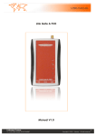
1
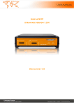
GSM ISDN Gateway Link Gate ISDN In blue, only on 6.5 version. Since Ja nua ry 05 OGM & SMS will be bundle together ( A ll in one option). For easier use, pleased deactivate the PIN code of your SIM card. User manual v 2.0 rev 2.0 Ce document est la propriété de Linkcom. Toute reproduction même partielle est strictement interdite classe DR classement LGISDNeng 6.5 numéro 002.02 date 09/11/04 page 1/22 Table of content 1. Specifications of Link Gate ISDN 1.1 Product overview 1.2 Specifications 1.3 Link Gate router 1.4 Optional modules 1.5 Package content 3 3 3 4 4 4 2. Installation of the Link Gate ISDN 2.1 Installation step by step for SIM cards and cables. 5 5 3. Initialisation of the Gatew ay 3.1 Indication of Leds 3.2 Possible problems when putting into operation 7 7 8 4. Link Gate ISDN configuration 4.1 Installation of GSM Set 4.2 Start GSM Set 4.3 Setting of Link Gate ISDN 4.4 Direct Dialling Code selection 4.4.1 DISA 4.5 Recording outgoing message (OGM) 4.5.1 Recording through an internal phone 4.5.2 Recording with OGM Rec. Software and « serial/jack » adaptor 4.5.3 Benefits of the software 4.6 ISDN parameters selection 4.7 Save and restore parameters 4.8 Remote configuration module 4.9 SMS Mail 9 9 10 11 13 13 13 13 14 14 14 15 16 18 5. Appendix 5.1 Range of values 5.2 Editing the selected values of individual parameters 5.3 Editing in parameters field 5.4 Editing in tables 5.5 RS 232 interconnection cable 5.6 Hardware reset 21 21 21 21 21 22 22 Ce document est la propriété de Linkcom. Toute reproduction même partielle est strictement interdite classe DR classement LGISDNeng 6.5 numéro 002.02 date 09/11/04 page 2/22 1. Specifications of ISDN Link Gate ISDN Note: ISDN 1 and 2 have same basic features, the difference is that ISDN 2 have 2 module instead ISDN 1 have only 1 GSM module. 1.1 Product overview LINK GATE ISDN is a Gateway with 1 or 2 GSM modules (Siemens TC 35i) LINK GATE ISDN connected to your PABX, will reduce your phone bills. The gateway is a metallic box, including the following connections and signalizations 1 power supply 230V / 50Hz AC/DC. 1 RJ 45 for PABX connection. 1 RJ 45 for synchronization connection. 1 or 2 mini fme connections for antennas 1 or 2 SIM card holder Leds for indications of use. 1.2 Specifications Connection to the exchange through ISDN S0 interface with DSS1 signaling in NT mode POINT TO POINT or POINT TO MULTIPOINT exchange S0 interface Connection to DTMF extension line through direct dialing Connection directly to 2 operators or determined lines up called SIM card Connection to the 2 operators after a time period elapse (adjustable) to select an extension line Transfer of the number of the calling subscriber in the exchange (CLIP) Limitation of outgoing calls in GSM network Limitation of incoming calls from GSM network Priority connection through either the 1st or the 2nd GSM module (LCR) Switchable automatic channels changing Smart Call back – automatic incoming calls routing up CLIP Volume setting in both directions separately for each GSM module Setting own time rate by 1 second or only in case of establishing connection Selection of the GSM service provider separately for each GSM module OGM module recordable message from PC ( MP3, Wav) SIM card protection using PIN Detailed gate parameters setting from PC through a program for Windows 3.1/95/98/2000/XP Power supply 9-15 V DC or 8-12 V AC Ce document est la propriété de Linkcom. Toute reproduction même partielle est strictement interdite classe DR classement LGISDNeng 6.5 numéro 002.02 date 09/11/04 page 3/22 Precaution for synchronization Some PABX having several ISDN lines which are not able to ensure synchronization on the various lines with a simple configuration. The marks of PABX concerned known to date are: Alcatel, Ericsson and Siemens. 1.3 Link Gate Router The gate is provided with ISDN input. The cable leading from this input must be connected to the former ISDN line (exchange line). The other connector (output ISDN line) is used as a standard ISDN line (connection to the exchange). In this way, the user does not lose the former IDSN line. After proper LCR setting, the selected calls are routed in GSM networks; the other calls pass further in the former ISDN line. The incoming calls are merged from both directions in the ISDN output. 1.4 Optional m odules Some modules are now available for the GSM Link Gate ISDN: a) OGM module Recording available with the software provide or through an ISDN phone. 10 seconds recording (see p 16) b) . SMS Server Send and received SMS through POP mail software. (For more details see SMS server manual. (p 21) c) Remote configuration Remote control of the Gateway, with a SIM card having data option. 1.5 Package content ISDN 1 1 1 1 1 1 1 1 1 ISDN 2 gateway Link Gate ISDN 1 magnetic antenna SIM card holder power supply installation CD RS 232 cable RJ 45 / RJ 45 cable for sy nchronization T f or RJ 45 Ce document est la propriété de Linkcom. Toute reproduction même partielle est strictement interdite classe DR 1 2 2 1 1 1 1 1 gateway Linkgate ISDN 2 magnetic antennas SIM card holders power supply installation CD RS 232 cable RJ 45 / RJ 45 cable for sy nchronization T f or RJ 45 classement LGISDNeng 6.5 numéro 002.02 date 09/11/04 page 4/22 2. Installation of the Link Gate ISDN In this chapter we will see how to install the gateway in your telephone installation. 2.1 Installation step by step, for SIM cards and cables a. Insert SIM card Carefull with PIN code Check as a preliminary if the SIM cards are protected by PIN code, if such is the case, you can use the software provided to program the PIN codes. (See 3.1.1. page 12) before inserting the cards. With a pencil or similar push the yellow button on the card holder to extract it, then install on the holder the card as bellow and replace it. Figure 1 Figure 2 Figure 3 Figure 4 b. Connection of antennas Figure 5 c. Connection of Bri to the Link Gate ISDN Figure 6 Ce document est la propriété de Linkcom. Toute reproduction même partielle est strictement interdite classe DR classement LGISDNeng 6.5 numéro 002.02 date 09/11/04 page 5/22 Some PBX don’t deliver Synch you can get it fro the land line. PBX needing synchronisation (no exhaustive list): Alcatel – Ericsson - Siemens Sy nchro is active Indicate communication is activ e Connection f or sy nchronization Connection f or communication with PABX _______________________________ How to use the T provide in the package. Figure 1 Figure 2 Figure 3 CAUTION (for synchronization) You can get synchronization from SO port of your PBX. e. Connection router version f. Connection of the Link Gate w ith a PBX Ce document est la propriété de Linkcom. Toute reproduction même partielle est strictement interdite classe DR classement LGISDNeng 6.5 numéro 002.02 date 09/11/04 page 6/22 g. Pow er supply connection 3. Initialisation of the Gateway 3.1 Indications of the leds a. LEDs up of the gatew ay Note : If you insert 2 SIM cards they will be activated in the following order , 1 then 2. Near each card holder you’ll find a red and green LED : SIM card inserted Connected to GSM network Green LED indicates SIM card inserted. Red LED (flashing slowly) indicates connection to the GSM network. Green LED must be always solid ON. Red LED will flash slowly in STD by mode and quickly when line is busy. Ce document est la propriété de Linkcom. Toute reproduction même partielle est strictement interdite classe DR classement LGISDNeng 6.5 numéro 002.02 date 09/11/04 page 7/22 b. Leds on the front Si tous fonctionnent correctement, la ou les DEL vertes sont allumées et clignote de manière régulière sur la face avant du Linkgate ISDN. En communication celle-ci devient fixe. Operation of GSM1,2 modules (green): LED is flashing – module logged in the network, rest condition LED lit up permanently – connection in process (call) Indication of error conditions in channels (red): LED extinguished – rest condition LED is flashing – error (more detailed information on the error can be f ound out by listing conditions after depressing the “test” pushbutton in the positioning routine – see below) Signalisation Green LED flashing Green LED solid ON Red LED is ON Signification Gateway is in std by mode Gateway is in communication There is a problem on the gateway When a red LED flashing on the front face, then there is a problem w ith the gatew ay. It is possible to create a file w hich w ill contain all information making it possible to diagnose the problem, to generate this file, click on the button "test" of the GSM set panel. The program w ill open in a new window all information relating to the gatew ay. It is possible to copy to stick and to print this test. 3.2 Possible problems when putting into operation Here bellow find the current . Problem No LED are lit up Quick “logging in” flashing of the red LED has not occurred. Solution Power supply error. Check connection to the mains and connection of the mains’ adapter to the gate The module is not logged in the network : Defective SIM card (or the card is incorrectly inserted in its compartment) Obsolete 5V SIM card (the module supports cards for 3V and lower voltage); Logging in GSM with PIN has been set and the PIN has not been set in the gate by the positioning routine; GSM signal is too weak. The dev ice is operating, howev er, the call contains a humming sound . Unsuitable positioning of the aerial with respect to any of the analogue telephone lines or an analogue telephone apparatus into which GSM transmission is induced (identical as in case of a car radio). It is necessary to test mutual position or totally relocate it. The dev ice is operating, howev er, an “echo” can be heard in the call. Echo is automatically eliminated by electronic means in the gate. If you hear a beep despite this measure, it could be caused by : Too improper impedance adaptation of the BTS channel to which either you or your counterpart are connected; Mobile telephone, which you are calling (some older types, some types of protective cases). Ce document est la propriété de Linkcom. Toute reproduction même partielle est strictement interdite classe DR classement LGISDNeng 6.5 numéro 002.02 date 09/11/04 page 8/22 4. Link Gate ISDN configuration The routine is intended for setting all the necessary gate parameters and detecting error conditions. The parameters are being set as w ell as the error conditions can be saved for later utilization. It is intended for Window s 3.1 to 2000 systems. Note : LINK GATE ISDN is configured by def ault without baring call f or the numbers with 10 digits, default password, and does not compose PIN code to starting. Each time you saf eguard new parameters in Linkgate ISDN, that will start again automatically. Pleased check connection w ith serial cable, then install the GSMSet softw are. 4.1 Installation of « Gsm SET » GSMSet software is on the CD prov ide in the package, when y ou insert the CD y ou see the window abov e, you can choose also your language. Ce document est la propriété de Linkcom. Toute reproduction même partielle est strictement interdite classe DR classement LGISDNeng 6.5 numéro 002.02 date 09/11/04 page 9/22 If you can’t see this w indow click on the « autorun» icone: Click on « Installing GSM SET », you’ll have this w indow : Click on ‘Continue’. The softw are will be installed on the GSMSet directory. 4.2 Start GSM Set Note : Check if serial cable is connected to com 1 or 2 of y our computer. Start the program from the shortcut on your deck or from start/ program/ gs m set. Link Gate ISDN use a protection code, default is 0000.. We recomend, if u are the PBX administrator to change it in the „ New passw ord“ put, then click on „SAVE“. Note : A wrong connection will display the f ollowing message « Wrong password » Note : In case of problem or password lost see appendix 5 Ce document est la propriété de Linkcom. Toute reproduction même partielle est strictement interdite classe DR classement LGISDNeng 6.5 numéro 002.02 date 09/11/04 page 10/22 To obtain the state of the Gatew ay to click it on the button "statut". All information concerning the gatew ay is posted w ith the screen:Caution! version of the software and not of the footbridge, to press on statute for version of the gatew ay. 4.3 Setting of the LINK GAT E ISDN During data transfer from or in the gate, the corresponding button w ill alw ays “turn grey” and the colour indicators in the button w ill indicate the type of the transfer (yellow for data send, green for data receive). If any error occurs during transfer or the access password does not w ork, the program w ill react w ith an error message. Do not forget to turn the appropriate com1 or com4 on! Configure the GSM m odules Configuration of module 1 and 2 is the same, pleased verify wish one you configure. a. Set the PIN Code If your SIM card have a PIN code indicate it in the PIN b. Programming MSN of the gatew ay In MSN pleased indicate the extention w here the call be route if necessary . Ce document est la propriété de Linkcom. Toute reproduction même partielle est strictement interdite classe DR classement LGISDNeng 6.5 numéro 002.02 date 09/11/04 page 11/22 c. Set the impulsion for taxation Generate a taxe impulsion beetween 0 to 99 seconds. d. Setting of outgoing (GSM) et incoming( ISDN) volume The “Volume ” fie ld allows adjust ing ca ll volume in both the outgoing direction (“GSM“ field) and the incoming direction (“ISDN“ field). Volume in the outgoing direction can be set in degrees 1 to 7 while in the incoming direction from 1 to 4. e. Call baring Permission of outgoing or incoming calls f. Redirection to GSM module In case of marking the”Re-route in GSM2“(GSM1) field, “overflow” of the enabled directions (selection see below) in the adjacent channe l is allowed. If the channel with the enabled direction is already busy calling, the gate will not refuse the call, but it will utilize the other channel (even if the direction is not on the list of enabled directions for this channel). . g. Baring Call Configuration On each module you can allow incoming and / or outgoing calls. Up to 12 blocks of enabled directions can be selected in each GSM module. The table of the enabled directions is accessible after clicking on the “ Enabled directions” button. If the table is not filled in, all directions are enabled. 1- up to 8-digit numbers can be w ritten in the first column of the table. The program substitutes any digits instead of not filled in digits from the right w hich checking the enabled direction. This means, instead of w riting the numbers 601,602,…609, it is possible to w rite only 60. Listing of enabled directions in groups is new in this program version. If the operator has three successive numbers differing from each other only by the last digit, this direction can be written as a group on a single line: the first column contains up to 8-digit number of the first direction (“from”) as in the case mentioned above and the last digit of the last direction is stored in the second column (i.e. the last digit of “to”) – see Fig. A group may be created only w ithin the range of one order of the last position – i.e. from 0 to 9! By proper filling in the tables of both modules (one module e.g. T- Mobile code, the other module Orange code), it is possible to achieve automatic re-routing of the outgoing call in the module allow ing cheaper calling through the given operator (LCR). Caution! The values are loaded in the table only after pressing the Enter button, m arking it w ith cursor or by m ouse clicking on another field of the table! After clicking on the “ Enabled directions” button, the table w ill be verified before closing. The operator is notified of wrong numbers or duplicate selection of values. In order the verified data can be sent to the gate from the table, close the tables before transfer! If they rem ain open, they w ill be closed autom atically and a check of data w ill be performed before transfer. In the event of errors in the tables, transfer w ill be blocked. After clearing the errors, transfer has to be repeated. Ce document est la propriété de Linkcom. Toute reproduction même partielle est strictement interdite classe DR classement LGISDNeng 6.5 numéro 002.02 date 09/11/04 page 12/22 Number of digits of direct dialling code 4.4. Direct dialling code selection The incoming calls can be handled in tw o ways: All calls can be automatically connected to a selected extension in the connected exchange 4.4.1. DISA Connection takes place in accordance w ith the selected MSNs (DDI) or direct dialling numbers of the operator separately for each channel. In this w ay, it is even possible to distinguish the calls incoming to individual telephone numbers of the GSM channels of the gate – the calls incoming to the telephone number of the first channel w ill be connected to the direct dialling code 11, incoming calls to the number of the other channel e.g. to the direct dialling code 12. If a number of digits in the direct dialling code are being set, the number w ill be higher than zero (max. 4 – Caution: the number should correspond w ith the number of digits of the direct dialling code of the exchange and selected MSNs or DDIs of individual GSM modules!), the callers may themselves dial directly using tone selection by preset number of digits to the required extension. The automatic operator w aits for a pre-selected number of seconds for direct dialling code selection. If it is not selected, the pre-selected number of the operator (according to a channel the call is incoming from) is dialled again. 4.5. Recording Outgoing message (OGM) Option You can choose to dial directly an internal phone (DISA). You can leave the messsage to invite the caller to compose an internal phone number or to indicate that he w ill be route to operator.This is useful to guide the caller. 4.5.1. Recording through an internal phone The gate can be provided additionally w ith a board with a digital recorder of “messages” for individual GSM channels. When collecting an incoming call through direct dialling, these messages are alw ays replayed. If the “rec” field has been checked, 2 extensions accessible from a number in GSM1 module are added in the system: message for GSM1 w ith the number 1 and a message for GSM2 w ith the number 2. After establishing connection w ith the number for the GSM1 module dialling the corresponding direct dialling code (*1 or *2), a short tone w ill sound – alerting to start of recording. After message recording (max. 10 sec.), the record is terminated by hanging up. Caution! You m ust select a 2-digit direct dialling code! Ce document est la propriété de Linkcom. Toute reproduction même partielle est strictement interdite classe DR classement LGISDNeng 6.5 numéro 002.02 date 09/11/04 page 13/22 4.5.2. Record w ith OGMRec software and « serial-jack » adaptor Name of the audio file 1 Percent of memory used by module Stop record Rec button for 2nd module Search the audio file Rec button for 1st module Adaptator« Série-Jack » 4.5.3. Benefits of the software The quality w ill be better than through a nor mal phone, and also it w ill be easier to mix voice and music before recording it on the module. 4.6 ISDN parameters selection Point to Point ( PPP) & Point to Multipoint ( PTMP) The telephones connected to the GSM gate mostly do not include a pushbutton for establishing connection by the dialled number as GSM telephones. This “defect” is by-passed by selecting a fixed number of digits after which sending of the dialled number ( max. digits parameter here) takes place in case of GSM gates. Sending the number if another digit is not selected w ithin the preset time (w aiting parameter here) period is another w ay. Of course, both parameters can be combined in a suitable w ay. The gate supports transfer of CLIP from the GSM netw ork in ISDN, i.e. to a telephone connected to an extension (if the device allow s it). Here it is advantageous to use the parameter for deleting the initial digits from CLIP (e.g. deleting +42 in order not to “confuse” LCR exchanges w hen calling back to the displayed number). Ce document est la propriété de Linkcom. Toute reproduction même partielle est strictement interdite classe DR classement LGISDNeng 6.5 numéro 002.02 date 09/11/04 page 14/22 Setting protocol on S0 – PTP or PTMP. In case of PTPM, MSNs are selected in direct dialling code, while a direct dialling identifier for PTP. The second w ay is the time elapsed betw een dialing 2 numbers, w hen the time is too long the gatew ay will dialed the number. Setting a type of dialling tone w ith w hich the gate is signalled: No tone (silence) Continuous tone 440 HZ (default) Morses R (preset) Morses A The best w ay in numerous configurations in T0 is PTMP instead S0. PTP or PTMP : Point to point or point to multipoint Max digit: Numbers dialled before the gateway sends the call without wait. Wait: How many seconds the gateway will wait before sending the call if the dialled numbers don’t have the size preset in « max digits ». Clear: The gateway support CLIP from GSM to ISDN. You can see incoming call numbers on internal phones. (if PBX support this feature). You can erase first digits of numbers, for example: clear +33 – country code). Most PBX doesn’t like + (ex +336…) so is better to put 1 to eliminate it. -Route to ISDN (router) : Route a call to ISDN w hen busy.(Only on “router“ version) 4.7 Save and restore parameters. You can easily save and restore your values on computer and recall them each time you need. To save all new values, click on „SAVE TO PC“ Ce document est la propriété de Linkcom. Toute reproduction même partielle est strictement interdite classe DR classement LGISDNeng 6.5 numéro 002.02 date 09/11/04 page 15/22 File w ill be save at *.BGI format Find a file w here to save your actual configuration To restore confiuration click on «Load from PC » chosse the file, click Ok then click on „save, the gatew ay w ill accept the new configuration. 4.8 Rem ote configuration module The gate can be additionally provided w ith a board allow ing identical w ork at gate configuration as through the RS-232 cable in a remote w ay through a modem. Enabled data calling for the GSM1 module and a modem connected to PC in w hich the GSMset program of the version 5 and higher is running are the necessary conditions. Ce document est la propriété de Linkcom. Toute reproduction même partielle est strictement interdite classe DR classement LGISDNeng 6.5 numéro 002.02 date 09/11/04 page 16/22 Requirements for the modem: GSM, ISDN or modem for analogue commutated line connected to COM1 or COM2 (it can be even a virtual one formed through USB). Auto-bauding or fixed communication rate set to 9,600 Bd. Potential other requirements for modem setting given by the communication netw ork connected that are usually to be set in the initialising chain have to be located in the initialising chain in the national configuration file gsmset.cfg in the directory gsmset. The chain is added behind the command ATE0 (echo sw itching off): Inimodem=“ATE0“ E.g. inimodem=“ATE0X3“ to sw itch off “dial tone“ detection. Work from configuration through RS-232 can be turned on to configuration through modem by marking the “modem“ parameter in the GSMSET program. Another element – “ListBox“ for selection of the telephone number of the gate that w ill be configured in a remote w ay w ill appear under the field for ISDN parameters setting. The background information for this list is read from the file “modems.csv“ in the directory of the GSMSET program. The program w ill list the background data in alphabetical order automatically. The file can be created either manually in any text editor, by export from any database or table program (csv format separated w ith commas) or by exporting an Outlook directory w ith the appropriate items (again, csv format separated w ith commas). The names of individual items or columns should be “name“, “ modem“, “file“. The “name“ field is to be used to save an identifier (name of location, etc.) of the gate. The telephone number of the first module of the gate should be entered in the “ modem“ field. The “ref” field is intended for a program for batch (mass) remote configurations that utilizes the same background data. If such background data (file) do not exist, it is possible to write the required telephone number for connection directly in the w indow . By confirming your selection from the list (double-click) or by confirmation of the w ritten number ( Enter), the system w ill take the telephone number selected for connection into account. The valid selection is confirmed by a change of colour of the field w ith the selection. To reduce the number of errors (accidental change of the number by unwanted clicking, etc.), the colour of the field is turned to w hite in case of repeated selection and it is necessary to confirm your selection again. After confirmed selection of the number of the gate configured in a remote w ay, it is possible to work with the program in the same w ay as in case of local configuration. When clicking on the corresponding button, the program w ill alw ays perform initialisation of the modem at first, dial the telephone number selected and establish connection w ith the selected gate. After connection is established, it reads or stores data. Operation is again indicated w ith LEDs in the corresponding pushed button. Data transfer at remote configuration is slow er and for that reason, also the LEDs flash slow er and configuration takes more time. After data transfer termination, the program w ill interrupt connection automatically and the modem w ill hang up. If any error occurs during communication w ith the modem, the program w ill report the error. If any error (transfer error, wrong password, etc.) occurs during connection, the program w ill detect the error again w ith the corresponding error message and w ill terminate connection automatically again and the modem w ill hang up. Ce document est la propriété de Linkcom. Toute reproduction même partielle est strictement interdite classe DR classement LGISDNeng 6.5 numéro 002.02 date 09/11/04 page 17/22 or MODEM error Insert a phone number Choose a number in the list To route the calls to ISDN when Gateway is busy Not forget to choose the Right port for modem 4.9 SMS Mail You can use the gatew ay in order to send and receive SMS through a PC equipped w ith the SMS Server software. You can send and receive SMS through the Gatew ay without licence, but all the send and received mail w ill be limited to 10 characters w ith a demo text SMS Mail acts as a standard POP Server, so you can easily implement the SMS solution into your computer netw ork. Attention: Not compatible With Outlook Exchange How does it work : Like a classical POP server,you can create users(using aliases), in order to have a single Sim card but several accounts. Installation a nd configuration of SM S MA IL You can install a copy of SMS Mail on a computer equipped w ith Microsoft Windows. Insert the Linkgate Disc in the PC. A w indow will show (html page) click on « SMS Server » and save the file on your hard drive (w herever you w ant). If you have purchase a licence, please insert it in the IMEI Key field Ce document est la propriété de Linkcom. Toute reproduction même partielle est strictement interdite classe DR classement LGISDNeng 6.5 numéro 002.02 date 09/11/04 page 18/22 SMS licence key in the zone: ‘IMEI key’ You can only use one key per GSM module (the licence key is associated to the IMEI of the gsm module) You need to reboot the software in order to fully use SMS MAIL. If you want to start SMS Mail with Windows, check Start at program beginning’ in ‘more settings’ options. In order to use the memory of the computer instead of the SIM card, you have to define a synchronisation period in order to send/receive the SMS. During this send/receive time the gateway changes his state into DATA mode, so you are not able to call during a synchronisation. You can also configure the incoming and outgoing port of the SMS Mail software (default: 25 and 110). Click on ‘Start at program beginning’ Ce document est la propriété de Linkcom. Toute reproduction même partielle est strictement interdite classe DR classement LGISDNeng 6.5 numéro 002.02 date 09/11/04 page 19/22 For starting the mail server click on ‘start’: Setup a mail client Here are the settings of SMS MA IL: POP: IP or name of the computer w hich is connected to the Linkgate SMTP: IP or name of the computer w hich is connected to the Linkgate Please make sure you are using the good communication ports. Send and receive SMS : If you w ant to correctly distribute the received SMS, you must respect the follow ing rules: -the SMS should contain the name of the computer OR -the alias of the computer name In a received message the sender should w rite the name of the computer as follow : #name_of_the_computer_or_alias# body of the SMS You can send a SMS to multiple computers by separating the names w ith a coma: #name01,name02,name03…# body of the SMS If you w ant to send a SMS from your pop client, please use the follow ing syntax: SM [email protected] , the X’s represents the phone number of the receiver After a mail synchronisation the SMS MA IL server w ill extract the phone from the address SM [email protected] and w ill send it through the GSM netw ork. Ce document est la propriété de Linkcom. Toute reproduction même partielle est strictement interdite classe DR classement LGISDNeng 6.5 numéro 002.02 date 09/11/04 page 20/22 5 Appendix 5.1 Range of values Function N° of digits PIN 0000 - 9999 Pulse each 1-2 0 - 99 Volume GSM 1 1-7 Volume ISDN 1 1-4 Permitted directions 0-4 0 - 9999 Passw ord 4 0000 - 9999 DISA 1 0-4 Wait 1 0-9 MSN (DDI) 1-4 0 - 9999 Max digits ISDN 1-2 1 - 99 Wait for 1-2 1 - 99 Erase CLIP 1 0-9 Connexion v ia Clip 1 - 10 0 - 9999999999 Internal communication 1-4 0 - 9999 5.2 Range Editing the selected values of individual parameters: With respect to the effort to ensure compatibility w ith the system base as large as possible (Windows 3.1 up to XP), the w ay of editing is somehow archaic and unusual for the present age. 5.3 Editing in parameters fields The values can be w ritten in a standard way upon location of the cursor in the field. Deleting values can be performed only from the back using the Backspace key. The complete value can be rew ritten in a usual w ay, i.e. by marking the complete value and, consequently, by loading a new data item. . 5.4 Editing in Tables A table cell is alw ays edited as a unit – i.e. individual digits may not be rewritten. If you click with the mouse (or cross with the cursor over) on the selected cell and start writing, the complete value in the cell w ill be rew ritten. The complete value in a cell can be again deleted only using the Backspace key. The value in a cell can be saved either using the Enter key or only after crossing over with the cursor or mouse clicking on another cell. This rule is applied also to deleting. Ce document est la propriété de Linkcom. Toute reproduction même partielle est strictement interdite classe DR classement LGISDNeng 6.5 numéro 002.02 date 09/11/04 page 21/22 5.5 RS 232 interconnection cable A standard series cable w ith 9-pin connector on both ends DTE-DCE ( modem 9-9) is used to interconnect the gate w ith your PC. It is also marketed under the designation “ mouse extension cable”. The cable “zero m odem” or “lapling“ has RX and TX crossed and cannot be used directly! If you wish to use this cable w ith an adapter, the adapter has to contain crossing again! If this is not the case, the link DTE- DTE (for interconnection of 2 PCs) w ill be formed that w ill not operate. Non-operating cable w ill by indicated by the message “Invalid passw ord” when attempting to communicate. 5.6 Hardw are Reset In case of lost passw ord, or inactive modifications in configuration use hard reset. 1 – Unplug the pow er supply 2 – Short-circuit pins 2 and 3 of DB 9 located under the GA TEWAY. 3 – Plug the pow er supply 4 – Wait 5 seconds 5 – Keep off the metalic piece from the DB 9 6 – Reboot the Gatew ay www.linkcom.net [email protected] Hot Line : 08 26 46 79 00 (France only) Ce document est la propriété de Linkcom. Toute reproduction même partielle est strictement interdite classe DR classement LGISDNeng 6.5 numéro 002.02 date 09/11/04 page 22/22