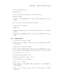
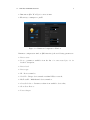
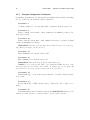
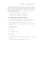
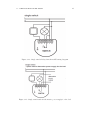
1
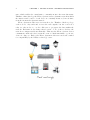
Advanced User’s Guide
8.VIII.2012 ver. 1.02\beta
Contents
Contents
I
1 Fibaro System - General Information
1
2 The
2.1
2.2
2.3
3
3
4
4
Z-Wave Protocol
Device Types . . . . . . . . . . . . . . . . . . . . . . . . . . . . . .
How the network works . . . . . . . . . . . . . . . . . . . . . . . .
Routing Principles . . . . . . . . . . . . . . . . . . . . . . . . . . .
3 Fibaro System Modules
3.1 Fibaro Dimmer FGD211 . . . . . . . . . . . . . .
3.1.1 Product Characteristics . . . . . . . . . .
3.1.2 Specifications . . . . . . . . . . . . . . . .
3.1.3 Example Configuration Parameters . . . .
3.1.4 Associations . . . . . . . . . . . . . . . . .
3.1.5 Tips and Tricks . . . . . . . . . . . . . . .
3.1.6 Wiring Diagrams - Dimmer . . . . . . . .
3.2 Relay Switch 2x1,5kW FGS211 . . . . . . . . . .
3.2.1 Product Characteristics . . . . . . . . . .
3.2.2 Specifications . . . . . . . . . . . . . . . .
3.2.3 Example Configuration Parameters . . . .
3.2.4 Associations . . . . . . . . . . . . . . . . .
3.2.5 Tips and Tricks . . . . . . . . . . . . . . .
3.3 Relay Switch 1x3kW FGS211 . . . . . . . . . . .
3.3.1 Product Characteristics . . . . . . . . . .
3.3.2 Specifications . . . . . . . . . . . . . . . .
3.3.3 Example Configuration Parameters . . . .
3.3.4 Associations . . . . . . . . . . . . . . . . .
3.3.5 Wiring diagrams - Relay Switch 1x3,0kW
3.4 Roller Shutter FGR211 . . . . . . . . . . . . . . .
I
.
.
.
.
.
.
.
.
.
.
.
.
.
.
.
.
.
.
.
.
.
.
.
.
.
.
.
.
.
.
.
.
.
.
.
.
.
.
.
.
.
.
.
.
.
.
.
.
.
.
.
.
.
.
.
.
.
.
.
.
.
.
.
.
.
.
.
.
.
.
.
.
.
.
.
.
.
.
.
.
.
.
.
.
.
.
.
.
.
.
.
.
.
.
.
.
.
.
.
.
.
.
.
.
.
.
.
.
.
.
.
.
.
.
.
.
.
.
.
.
.
.
.
.
.
.
.
.
.
.
.
.
.
.
.
.
.
.
.
.
.
.
.
.
.
.
.
.
.
.
.
.
.
.
.
.
.
.
.
.
.
.
.
.
.
.
.
.
.
.
.
.
.
.
.
.
.
.
.
.
.
.
.
.
.
.
.
.
.
.
.
.
.
.
.
.
.
.
.
.
7
7
7
8
10
11
12
13
16
16
16
18
18
19
23
23
23
25
25
26
29
II
CONTENTS
3.5
3.4.1 Product Characteristics . . . . . . .
3.4.2 Specifications . . . . . . . . . . . . .
3.4.3 Roller Shutter Calibration . . . . . .
3.4.4 Example Configuration Parameters .
3.4.5 Associations . . . . . . . . . . . . . .
3.4.6 Connecting Scheme - Roller Shutter
Dimmer Bypass FGB 001 . . . . . . . . . .
3.5.1 Specifications . . . . . . . . . . . . .
3.5.2 Connecting Scheme - Bypass . . . .
.
.
.
.
.
.
.
.
.
.
.
.
.
.
.
.
.
.
.
.
.
.
.
.
.
.
.
.
.
.
.
.
.
.
.
.
.
.
.
.
.
.
.
.
.
.
.
.
.
.
.
.
.
.
.
.
.
.
.
.
.
.
.
.
.
.
.
.
.
.
.
.
.
.
.
.
.
.
.
.
.
.
.
.
.
.
.
.
.
.
.
.
.
.
.
.
.
.
.
4 Wireless Z-Wave Sensors
4.1 Universal Binary Sensor . . . . . . . . . . . . . . . . . . . . . .
4.1.1 Specifications . . . . . . . . . . . . . . . . . . . . . . . .
4.1.2 Example Configuration Parameters . . . . . . . . . . . .
4.1.3 Universal Binary Sensor - Inclusion / Exclusion . . . . .
4.1.4 Wiring Diagrams - Universal Binary Sensor . . . . . . .
4.2 Danfoss Living Connect Electronic Thermostat . . . . . . . . .
4.2.1 Specifications . . . . . . . . . . . . . . . . . . . . . . . .
4.2.2 Danfoss Thermostat Inclusion/Exclusion . . . . . . . . .
4.2.3 Adapters . . . . . . . . . . . . . . . . . . . . . . . . . .
4.3 Motion Sensor . . . . . . . . . . . . . . . . . . . . . . . . . . .
4.3.1 Specifications . . . . . . . . . . . . . . . . . . . . . . . .
4.3.2 Everspring Motion Sensor Inclusion/Exclusion . . . . .
4.4 Flood Sensor . . . . . . . . . . . . . . . . . . . . . . . . . . . .
4.4.1 Specifications . . . . . . . . . . . . . . . . . . . . . . . .
4.4.2 Everspring Flood Sensor Inclusion/Exclusion . . . . . .
4.5 Temperature and Humidity Sensor . . . . . . . . . . . . . . . .
4.5.1 Specifications . . . . . . . . . . . . . . . . . . . . . . . .
4.5.2 Everspring Temp./Humidity sensor Inclusion/Exclusion
4.6 Door / Window Sensor . . . . . . . . . . . . . . . . . . . . . . .
4.6.1 Specifications . . . . . . . . . . . . . . . . . . . . . . . .
4.6.2 Aeon Labs D/W Sensor Inclusion/Exclusion . . . . . . .
4.7 Smoke Detector . . . . . . . . . . . . . . . . . . . . . . . . . . .
4.7.1 Specifications . . . . . . . . . . . . . . . . . . . . . . . .
4.7.2 Smoke Sensor Inclusion/Exclusion . . . . . . . . . . . .
5 Home Center 2
5.1 HC2 Finder . . . . . .
5.2 Your House . . . . . .
5.3 Rooms . . . . . . . . .
5.4 Devices . . . . . . . .
5.4.1 Z-Wave Devices
. . . . . .
. . . . . .
. . . . . .
. . . . . .
Inclusion
.
.
.
.
.
.
.
.
.
.
.
.
.
.
.
.
.
.
.
.
.
.
.
.
.
.
.
.
.
.
.
.
.
.
.
.
.
.
.
.
.
.
.
.
.
.
.
.
.
.
.
.
.
.
.
.
.
.
.
.
.
.
.
.
.
.
.
.
.
.
.
.
.
.
.
.
.
.
.
.
.
.
.
.
.
.
.
.
.
.
.
.
.
.
.
.
.
.
.
.
.
.
.
.
.
.
.
.
.
.
.
.
.
.
.
.
.
.
.
.
.
.
.
.
.
.
.
.
.
.
.
.
29
29
31
31
31
31
33
33
34
.
.
.
.
.
.
.
.
.
.
.
.
.
.
.
.
.
.
.
.
.
.
.
.
35
36
37
37
39
39
44
45
46
47
48
48
49
50
51
51
52
52
53
54
55
55
56
57
57
.
.
.
.
.
59
59
61
62
63
63
III
CONTENTS
5.5
5.6
5.7
5.8
5.9
5.4.2 IP Camera Inclusion . . . . . . . .
5.4.3 Creating Virtual Devices . . . . . .
5.4.4 Deleting Devices . . . . . . . . . .
Scenes . . . . . . . . . . . . . . . . . . . .
5.5.1 Example Scenes . . . . . . . . . . .
Linked Devices . . . . . . . . . . . . . . .
5.6.1 Linked Devices - Heating . . . . .
5.6.2 Linked Devices - Air Conditioning
5.6.3 Linked Devices - Humidity . . . .
5.6.4 Video Gate . . . . . . . . . . . . .
Panels . . . . . . . . . . . . . . . . . . . .
5.7.1 SMS Panel . . . . . . . . . . . . .
5.7.2 Alarm Panel . . . . . . . . . . . .
5.7.3 Heating Panel . . . . . . . . . . . .
5.7.4 Heating Panel . . . . . . . . . . . .
5.7.5 Humidity Panel . . . . . . . . . . .
5.7.6 History Panel . . . . . . . . . . . .
5.7.7 Access Control . . . . . . . . . . .
5.7.8 Notifications Panel . . . . . . . . .
5.7.9 Localization Panel . . . . . . . . .
Configuration . . . . . . . . . . . . . . . .
5.8.1 General . . . . . . . . . . . . . . .
5.8.2 LAN Settings . . . . . . . . . . . .
5.8.3 Location . . . . . . . . . . . . . . .
5.8.4 Backup . . . . . . . . . . . . . . .
Recovery Mode . . . . . . . . . . . . . . .
List of Figures
.
.
.
.
.
.
.
.
.
.
.
.
.
.
.
.
.
.
.
.
.
.
.
.
.
.
.
.
.
.
.
.
.
.
.
.
.
.
.
.
.
.
.
.
.
.
.
.
.
.
.
.
.
.
.
.
.
.
.
.
.
.
.
.
.
.
.
.
.
.
.
.
.
.
.
.
.
.
.
.
.
.
.
.
.
.
.
.
.
.
.
.
.
.
.
.
.
.
.
.
.
.
.
.
.
.
.
.
.
.
.
.
.
.
.
.
.
.
.
.
.
.
.
.
.
.
.
.
.
.
.
.
.
.
.
.
.
.
.
.
.
.
.
.
.
.
.
.
.
.
.
.
.
.
.
.
.
.
.
.
.
.
.
.
.
.
.
.
.
.
.
.
.
.
.
.
.
.
.
.
.
.
.
.
.
.
.
.
.
.
.
.
.
.
.
.
.
.
.
.
.
.
.
.
.
.
.
.
.
.
.
.
.
.
.
.
.
.
.
.
.
.
.
.
.
.
.
.
.
.
.
.
.
.
.
.
.
.
.
.
.
.
.
.
.
.
.
.
.
.
.
.
.
.
.
.
.
.
.
.
.
.
.
.
.
.
.
.
.
.
.
.
.
.
.
.
.
.
.
.
.
.
.
.
.
.
.
.
.
.
.
.
.
.
.
.
.
.
.
.
.
.
.
.
.
.
.
.
.
.
.
.
.
.
.
.
.
.
.
.
.
.
.
.
.
.
.
.
.
.
.
.
.
.
.
.
.
.
.
.
.
.
.
.
.
.
.
.
.
.
.
.
.
.
.
.
.
.
.
.
.
.
.
.
63
64
66
66
67
68
70
71
72
73
74
74
76
78
79
80
80
81
84
85
86
86
87
89
90
91
93
Chapter 1
Fibaro System - General
Information
Fibaro is a wireless, intelligent building automation system, based on the Z-Wave
communication protocol. Thanks to MESH network topology, Fibaro has certain
advantages over competitive solutions, which establish a direct connection between the signals emitter and receiver. In such a situation the radio signal is
weakened by any obstacle in its way - walls, furniture etc. Each Fibaro System
component serves as a signal emitter and receiver, plus also as a signal repeater.
This is the main advantage of the Fibaro System - if establishing a direct connection between devices proves impossible, a connection may be established thanks
to the other devices serving as a signal repeaters.
The Fibaro System uses two-way communication between system components.
Communications are sent to devices and the devices send back communication
confirming the signal’s reception. This way each device reports its current state,
so that it may be easily determined if a certain action has been performed. Data
transmission security in the Fibaro System is comparable to that of wired home
automation systems.
Fibaro System uses a Z-Wave certified data transmission radio frequency e.g. 868,4 MHz in EU. Each individual network gets its own, unique identification number (home ID) which gives the possibility for two or more independent
Fibaro Systems to operate in the same building without any interference. Z-Wave
wireless communication serves as a certified standard, which assures compatibility for products produced by various manufacturers all over the world. Thanks to
that approach Z-Wave technology offers great potential for expansion and further
development.
Because Z-Wave intelligent systems work in Mesh topology, where each device
(node) serves as a transmitter and receiver. Each device (node) also reports it
1
2
CHAPTER 1. FIBARO SYSTEM - GENERAL INFORMATION
state, which enables the central unit to constantly monitor the networks status.
Thanks to this technology the Fibaro System creates a dynamic network in which
the function and location of each device is constantly monitored, in real time,
from the moment the System is started.
Fibaro System modules serve as network nodes. Thanks to Mesh topology,
each node not only sends and receives the radio signals, but also serves as a
relay for other nodes, i.e. nodes collaborate to propagate the data within the
network. Each time nodes change their location, or one of the nodes dies, the
network reconfigures itself automatically. This way the Fibaro System devices
communicate with each other even in the event of central unit failure, e.g. in case
of fire, flooding, etc. Each of the Fibaro System modules are tested and certified
for compatibility by the Z-Wave technology owner.
Chapter 2
The Z-Wave Protocol
The Z-Wave protocol uses 868,4 MHz radio frequency in Europe, 908,4 MHz in
USA and 921.4 in AUS/NZ on unlicensed ISM bands. The protocol was launched
with 9600 b/s data transmission but it has been raised to 40Kbps. Both versions
of the protocol are compatible. Data is transmitted in 8bit blocks, in which the
most important bit is always sent first. Each Z-Wave network has its unique
ID called HOME ID. In addition, each device gets its own ID - Node ID. Each,
newly added device gets two ID numbers - HOME ID and Node ID. Home ID is
the same for all devices within the network, while Node ID is unique for a given
node. If another controller (secondary master) is added to the network, it gets
the same HOME ID as the main controller.
2.1
Device Types
There are two types of devices in the Z-Wave protocol: Master and Slave. There
are two types of master devices: Primary and Secondary. There is always one
Primary Master Controller in each Z-Wave network, to manage devices inclusion/exclusion and preserve network settings. Secondary Master Controllers copy
this data from the Primary Master Controller. In the Fibaro System, the Primary
Master Controller is the Home Center 2.
The Secondary Master (secondary) -e.g. remote, or any other device bearing
Secondary Master’s characteristic. Controllers initiate data transmission within
the network. Slaves are devices serving as actors i.e. they perform tasks directed
by Master Devices.
3
4
2.2
CHAPTER 2. THE Z-WAVE PROTOCOL
How the network works
Managing network nodes is realized through two types of operation: including/excluding nodes and associating nodes. Including device to the network
means creating a new network node, while excluding device means deleting network node. Each Z-Wave network has one Primary Master Controller, able to
include/exclude devices (create/delete network node). Other controllers (Secondary Master Controllers) copy the informations from the Primary Master.
Adding/deleting node always starts with entering the Primary Master Controller
into learning mode and then by activating the device’s inclusion. The latter is
done by the switch connected to the device, a specially designated switch in the
device, or simply by clicking an icon in the system menu (Primary Master Controller’s users interface). Once the primary master controller receives information
from a new node, the node receives a Home ID (same for each node within the
network) and its unique Node ID. Association is a direct link between network
nodes, realised without any action from Primary Master Controller.
2.3
Routing Principles
In a typical wireless network the central controller has a direct wireless connection to all of the other networking nodes. This always requires a direct radio
link. In case of disturbances the controller does not have any backup route to
reach the nodes. However, Z-Wave is a wireless system that offers a very powerful
mechanism to overcome this limitation. Z-Wave nodes can forward and repeat
messages that are not in direct range of the controller. This gives greater flexibility as Z-Wave allows communication, even though there is no direct wireless
connection or if a connection is temporarily not available, due to some change in
the room or building.
Z-Wave is able to route messages via up to four repeating nodes. This is a
compromise between the network size and stability, and the maximum time a
message is allowed to travel in the network. Every node is able to determine
which nodes are in its direct wireless range. These nodes are called neighbours.
During inclusion and later on request, the node is able to inform the controller
about its list of neighbours. Using this information, the controller is able to
build a table that has all the information about possible communication routes
in a network. The user can access the routing table. There are several software
solutions, typically called installer tools, which visualise the routing table to
optimize the network setup. A controller will always try first to transmit its
message directly to the destination. If this is not possible it will use its routing
table to find the next best way to the destination. The controller can select up to
three alternative routes and will try to send the message via these routes. Only
2.3. ROUTING PRINCIPLES
5
if all three routes fail (the controller does not receive an acknowledgement from
the destination) the controller will report a failure.
Chapter 3
Fibaro System Modules
3.1
Fibaro Dimmer FGD211
Figure 3.1: Dimmer module, FGD-211
Radio controlled light dimming module, designed to work with light sources of
any type. May be connected to two-wire or three-wire electric installation (with or
without neutral wire). Fibaro Dimmer can switch or dim connected light source
either through radio waves or through the wall switch connected directly to it.
Automatically senses connected device, features automatic overload protection
switch-off and soft start function. Works as a dimmer or as a connector, with
two-wire or three-wire installations. In case of fluorescent light sources or certain
transformers, only on/off function may be possible.
3.1.1
Product Characteristics
As at light dimmer it operates under the following loads:
7
8
CHAPTER 3. FIBARO SYSTEM MODULES
• Conventional incandescent
• Halogen 230V
• Low voltage halogen 12V (with electronic transformers)
• Dimmable LED
• When used with FGB001 it may operate with any dimmable load up to
500W*
Moreover, as an electronic switch it may work with:
• Compact fluorescent lamps
• LED bulbs
• Fluorescent lamps with electronic ballast and the majority of conventional
ballasts
• When used with FGB001 it may operate with any dimmable load up to
500W
3.1.2
Specifications
• Power supply: 230V ±10%, 50Hz,
• Output Power: 25-500W (for resistive loads - 230V); 10-250W (for resistive
loads - 110V),
• Dimmer type: Leading-edge dimmer
• In accordance with EU standards: EN 55015 (noise) EN 60669-2-1 (operational safety), AS/NZS 3100 (general requirements for electrical products)
• Overcurrent protection: 2,5A,
• Circuit temperature limits: 105 ◦ C,
• Ambient temperature: from 10 to 40 ◦ C,
• For installation in boxes: ∅≥50mm,
• Radio protocol : Z-Wave,
• Radio Frequency: 868,4 MHz for EU; 908,4 MHz for US; 921,4 MHz for
AUS/NZ/BRA,
• Range: up to 50 m outdoors; up to 30 m indoors (depending on building
materials),
3.1. FIBARO DIMMER FGD211
9
• Dimensions (H x W x D): 15 x 42 x 36 mm.
• Electricity consumption: ¡0,8W
Figure 3.2: Dimmers Configuration Window
Dimmers configuration window (HC2 interface) shows following parameters:
• Device name
• Room - parameter available from the list of rooms created (see 5.3 for
detailed description,
• Device kind
• Device type
• ID - Devices number,
• Node ID - Unique devices number within Z-Wave network,
• EndPointID - Multichannel devices number,
• Controlled device - Parameter taken from available devices list,
• Show Slave Devices
• Power Output
10
CHAPTER 3. FIBARO SYSTEM MODULES
3.1.3
Example Configuration Parameters
Configuration parameters, for each module are available in the Advanced Settings
tab, for each device, in the Home Center 2 interface.
Parameter 8
% change assigned to one step (automatic operation). Default setting: 1%
Parameter 9
Time to switch between min. / max. dimm level at manual operation. Default setting: 0.05s
Parameter 10
Time to switch between max. / min. dimm level at remote operation. 0 turns
off smooth dimming level change.
WARNING inductive and capacitive devices must be set to 0 to work properly (fluorescent lamps, electric motors).
Parameter 12
Max. dimming level. Default setting: 99%
Parameter 13
Min. dimming level. Default setting: 2%
WARNING! Max level must be always higher then min.
NOTE In case of fluorescent lights or non-dimmable LEDs the max. dimming level must be set at 98%; min at 99%. If settings are too low when AC
powered motors are used, operation may result in motor failure.
Parameter 14
Wall Switch type - mono-stable (press switch) or bi-stable Default setting:
mono-stable.
Parameter 15
Double Click ON / OFF. Default setting: ON(double click = lights set to
100%)
Parameter 17
Stair switch function On / Off Stair Switch Off. WARNING! Dimmer works
with two bi-stable switches or infinite number of mono-stable switches.
3.1. FIBARO DIMMER FGD211
11
Parameter 18
Synchronize Dim level for associated devices On / Off. Default setting: OFF
3.1.4
Associations
Association lets a Dimmer trigger other Z-Wave devices, e.g. another Dimmer,
Relay Switch, Roller Shutter. Triggering is performed in direct communication
between devices, without contacting the Primary Master Controller (Home Center 2).
A Dimmer may associate with up to 16 ordinary devices or up to 7 multichannel devices per association group, from which 1 device is always a network
controller. Recommended number of devices per association - 10. The more
devices are associated, the longer time will take for association action to take
effect on each associated device.
Dimmer supports two association groups - I and II:
I association group is designated for Switch Key no.1,
II association group is designated for Switch Key no.2.
NOTE The following parameter refers to II association group:
Parameter 7
GET Device State before sending steering frame assigned to key no.2. Default Setting: GET frame sent, device state checked before sending association
command.
12
CHAPTER 3. FIBARO SYSTEM MODULES
3.1.5
Tips and Tricks
1. How to include a Dimmer module connected to fluorescent lamp?
To include a Dimmer connected to fluorescent lamp, please connect the
module and fluorescent lamp observing wiring diagram (operating manual),
connect power input and double click button ”B” or key switch connected
to S1 input. Fluorescent lamp should turn ON (Dimmer turns ON with
full power). Next, complete inclusion process as described in the operating
manual.
2. How to set parameters for fluorescent lamp?
• Parameter 10: 0 seconds,
• Parameter 13: 98%
3. What kind of dimming does the Fibaro Dimmer provides?
The Fibaro Dimmer is a Leading-Edge type dimmer. The module is compatible with universal transformers and those designed for leading-edge type
dimming (inclining sinusoid curve).
3.1. FIBARO DIMMER FGD211
3.1.6
13
Wiring Diagrams - Dimmer
1. Before beginning, please make sure power supply is disconnected.
2. Connect Dimmer observing wiring diagram shown below.
3. Insert Dimmer and wall switch into connecting box.
4. While completing point 3. please take special care to lay antenna wire
properly.
Symbols description:
• L - live wire,
• N - neutral wire,
• O - Dimmer output,
• Sx - power for Switch connected to the Dimmer,
• S1 - switch key 1 (also, enters Dimmer module into learning mode, see.
inclusion process),
• S2 - switch key 2,
• B - service key (used for including/excluding device, see S1).
Figure 3.3: Dimmer wiring diagram
14
CHAPTER 3. FIBARO SYSTEM MODULES
Figure 3.4: Dimmer wiring diagram - 2-wire connection
Figure 3.5: Dimmer wiring diagram - 3-wire connection
3.1. FIBARO DIMMER FGD211
Figure 3.6: Dimmer wiring diagram - 3 way connection
Figure 3.7: Dimmer wiring diagram - 4-way connection
15
16
CHAPTER 3. FIBARO SYSTEM MODULES
3.2
Relay Switch 2x1,5kW FGS211
Figure 3.8: Relay Switch 2x1,5kW module, FGS-221
The radio controlled Fibaro Double On/Off Relay Switch is designed to be
installed in standard wall switch boxes, or anywhere else where it is necessary to
operate two independent devices of 1,5kW power output each. The Fibaro Double
On/Off Relay Switch can switch connected devices on or off either through radio
waves or through the wall switch connected directly to it.
3.2.1
Product Characteristics
• Controlled by FIBARO system devices or any Z-Wave controller.
• Microprocessor control.
• Executive elements: relays.
• The device may be operated by mono-stable (press switch) and bi-stable
push-buttons.
3.2.2
Specifications
• Power supply: 24 - 230V ±10% 50/60Hz,
• Maximum load current for single AC output: 8A / 230V 50/60Hz*,
• Maximum load current for single DC output: 8A / 30V*,
• Output circuit power (resistive load-230V): 2 x 1,5 kW*,
• Comply with standards: EN 55015; EN 60669-2-1, AS/NZS 3100
• Temperature limits: 105 ◦ C,
• Operational temperature: from 0 to 40 ◦ C,
3.2. RELAY SWITCH 2X1,5KW FGS211
17
• For installation in boxes: ∅≥50mm,
• Radio protocol: Z-Wave,
• Radio Frequency: 868 MHz for EU; 908 MHz for US; 921 MHz for AUS/NZ/BRA
• Range: up to 50 m outdoors, up to 30 m indoors (depending on building
materials),
• Dimensions (H x W x D) 15 x 42 x 38 mm.
• Electricity consumption: ¡0,8W
* In case of load other than resistive, pay attention to the value of cosφ and
if necessary apply load lower than the rated load.
Figure 3.9: Relay Switch 2x1,5kW configuration window
Relay Switch 2x1,5kW configuration window (HC2 interface) shows the following parameters:
• Devices name
• Room - Parameter available from the list of rooms created (see 5.3 for
detailed description)
• Device kind
• Devices type
• ID - Devices number
• Node ID - Unique devices number within Z-Wave network,
18
CHAPTER 3. FIBARO SYSTEM MODULES
• EndPointID - Multichannel devices number
• Controlled Device - Parameter taken from available devices list
• Show Slave Devices
• Show Slave Devices
• Power Output
3.2.3
Example Configuration Parameters
Configuration parameters for each module are available in the Advanced Settings
tab for each device in he Home Center 2 interface.
Parameter 3
Relay Auto OFF after specified time. Default Setting: Auto OFF disabled.
Parameter 4 & 5
Relay 1 / 2 Auto OFF after specified time. Default Setting: 0,2s
Parameter 13
State Change (ON / OFF) for bistable switch (Parameter no.14). Default
Setting: key position change = ON or OFF.
Parameter 14
Switch Type - mono-stable (press switch) or bistable. Default Setting: monostable.
Parameter 15
Operating associated Dimmer / Roller Shutter, enable / disable. Default Setting: disable. (If enabled, hold or double click given key to trigger associated
Dimmer / Roller Shutter).
Parameter 16
Device On / Off after power cut. Default setting - OFF
3.2.4
Associations
Association lets Relay Switch 2x1,5kW trigger other Z-Wave devices, e.g. Dimmer, another Relay Switch, Roller Shutter, or a scene (only involving Home
Center 2). Triggering is performed in direct communication between devices,
without contacting the Home Center 2 (except for the use as a scene triggering
device).
3.2. RELAY SWITCH 2X1,5KW FGS211
19
Relay Switch 2x1,5kW may associate with up to 16 ordinary devices or up to
7 multi channel devices per association group, from which 1 device is always a
network controller. Recommended number of devices per association - 10. The
more devices that are associated, the longer it will take for association action to
take effect on each associated device.
Relay Switch 2x1,5kW supports two association groups - I and II:
I association group is designated for Switch Key no.1,
II association group is designated for Switch Key no.2.
3.2.5
Tips and Tricks
1. What is the minimum powering voltage?
Relay Switch 2x1,5kW may be powered by 24V DC current.
2. May I connect two different Live wires - one for the module, another one
for the device triggered by the module?
Yes, a Relay Switch 2x1,5kW may be connected to two independent circuits
at the same time - one powering the module, another one (even powered
by a different voltage) powering the circuit triggered by the module.
3. May I use Relay Switch 2x1,5kW in two and three wire electrical systems,
just like the Dimmer?
The Relay Switch 2x1,5kW is designed to work on three-wire electrical
system only, i.e. it needs the Neutral wire.
4. I would like to use two Relay Switch 2x1,5kW modules to control home
alarm control unit, but it is powered by 12V current.
In such a case another circuit, powering the Relay Switches (with 24V at
least) will be necessary (see p. 2)
5. Can I use the Relay Switch modules to operate floor heating?
Yes. These modules may be used to operate both electrical and hydraulic
floor heating systems, in such use the modules will be used to turn electric
valves ON or OFF. Heating itself will be programmed in the Heating Panel
in of the HC2. For monitoring temperature we recommended the use of a
DS18B20 sensor, together with a Fibaro Universal Binary Sensor.
Wiring Diagrams - Relay Switch 2x1,5kW
1. Before beginning, please make sure power supply is disconnected.
2. Connect Relay Switch 2x1,5kW observing wiring diagram shown below.
20
CHAPTER 3. FIBARO SYSTEM MODULES
3. Insert Relay Switch 2x1,5kW and wall switch into connecting box.
4. While completing point 3. please take special care to lay antenna wire
properly.
Symbol descriptions - Relay Switch 2x1.5kW :
• N - Neutral wire
• L - Live wire
• I - Output device power in
• O1 - Output 1
• O2 - Output 2
• S1 - Switch key 1 (also, enters the module into learning mode, see. inclusion
process)
• S2 - Switch key 2
• B - Service key (used for including/excluding device, see S1)
Figure 3.10: Single switch, Relay Switch 2x1,5kW connection diagram
3.2. RELAY SWITCH 2X1,5KW FGS211
Figure 3.11: Single switch with an alternative power supply for the load
Figure 3.12: Double switch, Relay Switch 2x1,5kW connection diagram
21
22
CHAPTER 3. FIBARO SYSTEM MODULES
Figure 3.13: Double switch with an alternative power supply for the load
3.3. RELAY SWITCH 1X3KW FGS211
3.3
23
Relay Switch 1x3kW FGS211
Figure 3.14: Relay Switch 1x3kW module, FGS-211
Radio controlled Fibaro Double On/Off Relay Switch is designed to be installed in standard wall switch boxes, or anywhere else where it is necessary to
operate one single device of 3,0kW power output. Fibaro Double On/Off Relay Switch can switch connected device on or off either through radio waves or
through the wall switch connected directly to it.
3.3.1
Product Characteristics
• Controlled by FIBARO system devices or any Z-Wave controller.
• Microprocessor control.
• Executive elements: relays.
• The device may be operated by mono-stable (press-switch) and bi-stable
push-buttons.
3.3.2
Specifications
• Power supply: 24 - 230V ±10% 50/60Hz,
• Maximum load current for single AC output: 8A / 230V 50/60Hz*,
• Maximum load current for single DC output: 8A / 30V*,
• Output circuit power (resistive load-230V): 2 x 1,5 kW*,
• Comply with standards: EN 55015; EN 60669-2-1, AS/NZS 3100
• Temperature limits: 105 ◦ C,
• Operational temperature: from 0 to 40 ◦ C,
24
CHAPTER 3. FIBARO SYSTEM MODULES
• For installation in boxes: ∅≥50mm,
• Radio protocol: Z-Wave,
• Radio Frequency: 868 MHz for EU; 908 MHz for US; 921 MHz for AUS/NZ/BRA
• Range: up to 50 m outdoors, up to 30 m indoors (depending on building
materials),
• Dimensions (H x W x D) 15 x 42 x 38 mm.
• Electricity consumption: ¡0,8W
* In case of load other than resistive, pay attention to the value of cosφ and
if necessary apply load lower than the rated load.
Figure 3.15: Relay Switch 1x3kW Configuration Window
Relay Switch 2x1,5kW configuration window (HC2 interface) shows following
parameters:
• Device name
• Room - Parameter available from the list of rooms created (see 5.3 for
detailed description)
• Device kind
• Devices type
• ID - Devices number
• Node ID - Unique devices number within Z-Wave network,
3.3. RELAY SWITCH 1X3KW FGS211
25
• EndPointID - Multichannel devices number
• Controlled Device - Parameter taken from available devices list
• Show Slave devices
• Show Slave devices
• Power Output
3.3.3
Example Configuration Parameters
Configuration parameters for each module are available in the Advanced Settings
tab for each device in he Home Center 2 interface.
Parameter 3
Relay Auto OFF after specified time. Default Setting: Auto OFF disabled.
Parameter 4
Relay Auto OFF after specified time. Default Setting: 0,2s
Parameter 13
State Change (ON / OFF) for bistable switch (Parameter no.14). Default
Setting: key position change = ON or OFF.
Parameter 14
Switch Type - mono-stable (press switch) or bistable. Default Setting: monostable.
Parameter 15
Operating associated Dimmer / Roller Shutter, enable / disable. Default Setting: disable. (If enabled, hold or double click given key to trigger associated
Dimmer / Roller Shutter).
Parameter 16
Device On / Off after power cut. Default setting - OFF
3.3.4
Associations
Association lets a Relay Switch 1x3,0kW trigger other Z-Wave devices, e.g. Dimmer, another Relay Switch, Roller Shutter, or a scene (only involving Home Center 2). Triggering is performed in direct communication between devices, without
contacting Home Center 2 (except for the use as a scene triggering device).
26
CHAPTER 3. FIBARO SYSTEM MODULES
Relay Switch 1x3,0kW may associate with up to 16 ordinary devices or up to
7 multi channel devices per association group, from which 1 device is always a
network controller. Recommended number of devices per association - 10. The
more devices that are associated, the longer it will take for association action to
take effect on each associated device
Relay Switch 1x3,0kW supports two association groups - I and II:
I association group is designated for Switch Key no.1,
II association group is designated for Switch Key no.2.
3.3.5
Wiring diagrams - Relay Switch 1x3,0kW
1. Before beginning, please make the sure power supply is disconnected.
2. Connect Relay Switch 1x3,0kW observing wiring diagram shown below.
3. Insert Relay Switch 1x3,0kW and wall switch into connecting box.
4. While completing point 3. please take special care to lay antenna wire
properly.
Symbol descriptions:
• N - neutral wire
• L - live wire
• I - output device power in
• O - output
• S2 - switch key 2,
• S1 - switch key 1 (also, enters the module into learning mode, see. inclusion
process),
• B - service key (used for including/excluding device, see S1)
3.3. RELAY SWITCH 1X3KW FGS211
Figure 3.16: Single switch, Relay Switch 1x3kW wiring diagram
Figure 3.17: Single switch with an alternative power supply for the load
27
28
CHAPTER 3. FIBARO SYSTEM MODULES
Figure 3.18: Double switch, Relay Switch 1x3kW wiring diagram
Figure 3.19: Double switch with an alternative power supply for the load
3.4. ROLLER SHUTTER FGR211
3.4
29
Roller Shutter FGR211
Figure 3.20: Roller Shutter module. FGR-221
Radio controlled module, designed to work with electric motors in blinds,
rollers, canopies. Fibaro Blind/Roller Shutter can control the connected device
either through radio waves or through the wall switch, connected directly to it.
Equipped with unique feature of monitoring current Roller/Blind position.
3.4.1
Product Characteristics
• Controlled by FIBARO system devices or any Z-Wave controller.
• Microprocessor control.
• Executive elements: relays.
• The device may be operated by mono-stable (press switch), bi-stable pushbuttons, dedicated roller blinds buttons.
NOTE Precise roller blind positioning is possible for blind witch mechanical
stop-switches. For roller blinds with electronic control, please turn OFF positioning function (parameter 10)
3.4.2
Specifications
• Power supply: 110 - 230V ±10% 50/60Hz,
• Power of supplied motor: up to 1kW for 230V; up to 500W for 110V
• Rated motor current - 4,3A / 230V 50/60Hz
• In accordance with standards: EN 55022; EN 61000; AS/NZS 3100
• Temperature limits: 105 ◦ C,
30
CHAPTER 3. FIBARO SYSTEM MODULES
• Operational temperature: from 0 to 40 ◦ C,
• For installation in boxes: ∅≥50mm,
• Radio protocol: Z-Wave,
• Radio Frequency: 868 MHz for EU; 908 MHz for US; 921 MHz for AUS/NZ/BRA.
• Range: up to 50 m outdoors, up to 30 m indoors (depending on building
materials)
• Dimensions (H x W x D): 15 x 42 x 36 mm
• Electricity consumption - ¡ 0,8W
Figure 3.21: Roller Shutter configuration window
Roller Shutter configuration window (HC2 interface) shows following parameters:
• Devices name
• Room - Parameter available from the list of rooms created (see 5.3 for
detailed description)
• Device kind
• Device type
• ID - Devices number
• Node ID - Unique devices number within Z-Wave network
• EndPointID - Multichannel devices number
• What device controls - Parameter taken from available devices list
• Show slave devices
3.4. ROLLER SHUTTER FGR211
3.4.3
31
Roller Shutter Calibration
After a successful inclusion process, the Roller Shutter module should be calibrated. The calibration process involves performing two complete cycles of opening/closing the roller blind. Properly completed calibration may be verified by
setting required position of the roller blind using the icon e.g. 30% of roller blind
opening - the actual opening should correspond to specified value/position.
3.4.4
Example Configuration Parameters
Parameter 10
Roller Blind positioning status. Default Setting: ON
Parameter 14
Switch Type - monostable (press switch) or bistable. Default Setting: 16%
3.4.5
Associations
Association lets Roller Shutter trigger other Z-Wave devices, e.g. Dimmer, Relay
Switch, another Roller Shutter, or a scene (only involving Home Center 2). Triggering is realised in direct communication between devices, without contacting
Home Center 2 (except for the use as a scene triggering device).
Roller Shutter supports two association groups - I and II:
I association group is triggered by single click of any Switch Key,
II association group is triggered by pressing and holding any Switch Key.
Roller Shutter may associate with up to 16 ordinary devices or up to 7 multi
channel devices per association group, from which 1 device is always a network
controller. Recommended number of devices per association - 10. The more
devices are associated, the longer time is needed for association action to take
effect on each associated device.
3.4.6
Connecting Scheme - Roller Shutter
1. Before beginning, please make sure power supply is disconnected.
2. Connect Roller Shutter observing connecting scheme shown below.
3. Insert Roller Shuttter and wall switch into connecting box.
4. While completing point 3. please take special care to lay antenna wire
properly.
32
CHAPTER 3. FIBARO SYSTEM MODULES
Symbols description
• L live wire
• N neutral wire
• S1 switch key 1 (also, enters the module into learning mode, see. inclusion
process)
• S2 switch key 2
• O1 output 1
• O2 output 2
• B - service key (used for including/excluding device, see S1)
Figure 3.22: Wiring diagram - Roller Shutter
3.5. DIMMER BYPASS FGB 001
3.5
33
Dimmer Bypass FGB 001
Figure 3.23: Bypass module, FGB-001
Bypass Fibaro is a device complementary to Fibaro Dimmer FGD211. Its
installation enables the Dimmer to dim light sources with minimum power consumption, such as e.g. single 0,5Watt LED. Please note it is possible to dim only
light sources clearly marked as dimmable.
3.5.1
Specifications
• Power source: 230V ±10% 50Hz
• Temperature limits: 105 ◦ C
• Outside dimmensions (L x W x H) - 17mm x 18mm x 8,3mm.
34
3.5.2
CHAPTER 3. FIBARO SYSTEM MODULES
Connecting Scheme - Bypass
Figure 3.24: Wiring diagram - Bypass
Chapter 4
Wireless Z-Wave Sensors
The Fibaro System consists of a constantly growing range of wireless sensors. All
of the sensors communicate using the Z-Wave protocol. Their main characteristic
is battery power supply allowing sensors to be installed almost anywhere, within
the range of Z-Wave network. The Expected maximum battery life is 2 - 3
years, and the battery state may be monitored via the Home Center 2. Z-Wave
wireless sensors do not serve as mesh network signal relays. For that reason all
of them should be included into system after being installed in desired places.
Because of they are battery powered, wireless sensors do not communicate with
the Home Center 2 on constant basis. They are referred to as ”sleeping nodes”,
i.e. Home Center 2 communicates with them (checking their status and network
presence) in certain time intervals, these are defined as the ”Wake up intervals”
parameter in the device’s configuration. In addition to regular, interval based
communication, each battery powered sensor communicates with the HC2 in
case of breach, arming or a forced change of state, i.e. in the case of detecting a
certain action.
35
36
CHAPTER 4. WIRELESS Z-WAVE SENSORS
4.1
Universal Binary Sensor
The Universal Binary Sensor is a wireless module designed for increasing any
binary output sensor’s functionality by adding possibility of wireless communication with Z-Wave network and Fibaro System. Moreover, the module enables
inclusion of DS18B20 temperature sensors to the Fibaro System. A single Universal Binary Sensor supports up to two binary sensors of any type, or four DS18B20
temperature sensors. The Universal Binary Sensor is so small it can be place inside the casing of a sensor or other device that needs to be increased functionality.
The Universal Binary Sensor may be used anywhere, where wireless data collection, from sensors, is needed. After the appropriate protection, the module may
be used in high humidity or temperature situations. The Universal Binary Sensor
was designed primarily for the use with existing wired and wireless alarm and
control systems, so that they could be easily integrated with the Fibaro System.
For the use with alarm system, the module is 100% transparent to parametric
lines.
Figure 4.1: Universal Binary Sensor - Icons Views
Product Characteristics:
• Controlled by Fibaro System devices or any other Z-Wave controller.
• Microprocessor control.
• Compatible with standard and parametric alarm lines (may be connected
to single alarm sensor with tamper button, or two alarm sensors without
tampers).
• Compatible with binary sensors (may be connected to two binary outlets).
• Compatible with DS18B20 temperature sensors (supports up to four DS18B20
temperature sensors).
4.1. UNIVERSAL BINARY SENSOR
4.1.1
37
Specifications
• Power supply: 9-30V ±10% DC
• Inputs: 2 floating inputs, 1 digital input 1-wire
• Outputs: 2 floating outputs
• Max. input voltage: 36V ±5% DC
• Output carrying capacity: 150mA
• Operational temperature: from 0 ◦ C to 40 ◦ C
• Radio protocol: Z-WAVE
• Radio Frequency: 868 MHz for EU; 908 MHz for US; 921 MHz for AUS/NZ/BRA.
• Range: up to 50 m outdoors, up to 30 m indoors (depending on building
materials)
• Number of supported DS18B20 temperature sensors: up to 4
4.1.2
Example Configuration Parameters
Configuration parameters, for each module, available in Advanced Settings tab,
for each device, in Home Center 2 interface.
Parameter 1
Delayed alarm cancellation at input IN1. This option enables you to define
additional time after which IN1 alarm gets cancelled after it’s breach is no longer
present.
Default value: 0
Parameter 2
Delayed alarm cancellation at input IN2. This option enables you to define
additional time after which IN2 alarm gets cancelled after it’s breach is no longer
present. Default value: 0
Parameter 3
Input 1 type.
Default value: 1 = INPUT NC (Normal Close)
Default value: 1 = INPUT NC (Normal Close)
Parameter 4
Input 2 type.
38
CHAPTER 4. WIRELESS Z-WAVE SENSORS
Default value: 1 = INPUT NCNC (Normal Close) Default value: 1 - INPUT
NC (Normal Close)
Parameter 5
Steering frame type for 1st association group, triggered from input IN1. Parameter enables setting alarm frame type or forces sending of steering frames
(BASIC SET).
Default value: 255 = BASIC SET
Parameter 6
Steering frame type for 2nd association group, triggered from input IN2. Parameter enables setting alarm frame type or forces sending of steering frames
(BASIC SET).
Default value: 255 = BASIC SET
Parameter 7
Parameter defining forced level of dimming/blinds opening in case TURN
ON/OPEN commands are sent to devices of 1st association group. In case of
alarms, alarm priority is defined.
Default setting enables turning device ON. In case of Dimmer this means
turning to last memorized status.
Default value: 255.
Parameter 8
Parameter defining forced level of dimming/blinds opening in case TURN
ON/OPEN commands are sent to devices of 2nd association group. In case of
alarms, alarm priority is defined.
Default setting enables turning device ON. In case of Dimmer this means
turning to last memorized status.
Default value: 255
Parameter 9
Alarm cancelling frame or turning the device off steering frame (Basic) deactivated. Allows you to deactivate the feature off and cancel alarms for devices
paired with the given input of Fibaro Sensor.
Default value: 0, for association groups 1 & 2 information is sent.
Parameter 10 The interval between temperature readings from all sensors
connected to the device. NOTE: The temperature reading from the sensor does
not result in sending a report to HC unit.
Default value: 20 sec.
Parameter 11
The interval between successive reports on the state of the temperature.
Forced report is sent immediately after the next reading of the temperature sensor
4.1. UNIVERSAL BINARY SENSOR
39
regardless of the setting of parameter No. 12
Default value: 200 sec.
NOTE Frequent reports on the state of the temperature make sense in the
case when the sensor is placed at the point where it is exposed to rapid changes
in ambient temperature. In other cases, we recommend you left the default value
of the parameter.
Parameter 12
Maximum allowed difference in temperature last reported and currently recorder
by the sensor. If the difference in temperature meets or exceeds defined level, then
report to device in third association group is sent. Parameter 10 defines intervals
between temperature readouts.
Value set at 0 means sensor reports each change in temperature.
Default value: 8 [ 0, 5 ◦ C]
Parameter 13
Alarm frames or steering frames sent in broadcast mode i.e. to all devices
within the device’s reach.
Default vaule = 0 (broadcast mode OFF).
NOTE Broadcast mode cancels ”single cast” communication with associated
devices for given channel.
Parameter 14 Scene activation. Scene number corresponds to button pushed.
Default value = 0
4.1.3
Universal Binary Sensor - Inclusion / Exclusion
After entering Home Center 2 into learning mode (described in 5), triple click
button ”B”.
4.1.4
Wiring Diagrams - Universal Binary Sensor
Please note:
• When using DS18B20 temperature sensors, it is recommended to use single
wire cables, no longer than 30 m.
• Do not arrange DS18B20 temperature sensors cables parallel to house electrical system cables (230V AC). High voltage AC wires may induce magnetic
field resulting in erroneous DS18B20 temperature sensors readouts.
• DS18B20 temperature sensors should be tested before being mounted in
desired locations.
40
CHAPTER 4. WIRELESS Z-WAVE SENSORS
• Depending on number of the devices connected to it, the Universal Binary
Sensor may be presented in HC2 interface as 3 to 7 different devices.
• In case of any changes in TP / TD line (1-wire) configuration, i.e. adding/removing
DS18B20 temperature sensors, it is necessary to exclude and re-include the
Universal Binary Sensor to Z-Wave network. Please note, HC2 will enter
learning mode only after all connected sensors are detected, which may take
up to 10 seconds.
• Do not connect sensors other than DS18B20 temperature sensor to TP /
TD line (1-wire).
• Do not connect devices not supporting 1-wire protocol to TP / TD line.
Lines not in use, must be isolated.
Symbol descriptions:
• Live wire - red
• GND (GROUND) - ground wire, blue
• IN1 - (INPUT 1) - input 1, yellow
• IN2 (INPUT 2) - input 2, green
• TP (TEMP POWER) - power (3,3V) to DS18B20 temperature sensor,
brown
• TD (TEMP DATA) - signal to DS18B20 temperature sensor, white
• ANT- antenna, black
• B -service button (used for including/excluding device)
• OUT1 - output no.1, assigned to input IN1
• OUT2 - output no.2, assigned to input IN2
4.1. UNIVERSAL BINARY SENSOR
Figure 4.2: Universal Binary Sensor - connections description
Figure 4.3: Universal Binary Sensor, standard alarm line
41
42
CHAPTER 4. WIRELESS Z-WAVE SENSORS
Figure 4.4: Universal Binary Sensor, parametric alarm line
Figure 4.5: DS18B20 temperature sensors connection diagram
Figure 4.6: DS18B20 connections description
4.1. UNIVERSAL BINARY SENSOR
Figure 4.7: Universal Binary Sensor connection diagram
43
44
CHAPTER 4. WIRELESS Z-WAVE SENSORS
4.2
Danfoss Living Connect Electronic Thermostat
Figure 4.8: Electronic Thermostat Danfoss Living Connect
The Danfoss living connect is an electronic radiator thermostat, which communicates with the Fibaro System through the Z-Wave wireless protocol. Desired
temperature is set by the simple click of a button or through Heating Panel in
HC2, and then Danfoss Living Connect opens/closes the radiator’s valve with an
electromechanical actuator. The thermostat features an open-window function,
which closes the valve if the temperature in the room is falling dramatically.
Figure 4.9: Danfoss Thermostat - Parameters Modification Window
Danfoss Thermostat configuration window (HC2 interface) shows following
parameters:
• Devices name
• Room - Parameter available from the list of rooms created (see 5.3 for
detailed description)
• Device kind
• Device type
• ID - Devices number
4.2. DANFOSS LIVING CONNECT ELECTRONIC THERMOSTAT
45
Figure 4.10: Danfoss Electronic Thermostat - configuration window
• Node ID - Unique device number within the Z-Wave network,
• EndPointID - Multichannel devices number
• Wake up interval - Time interval for HC2 to communicate with the thermosat (60 seconds at the minimum)
4.2.1
Specifications
• Radio frequency: 868.42MHz
• Actuator type: Electromechanical
• Recommended use: Household
• Mechanical strength: 70N
• Max. water temperature: 90 ◦ C
• Estimated battery life: 2 years
• Temperature measurement cycle: every 60 seconds
• Power supply: 2x1,5V AA battery
• Power consumption: 3mW in standby, 1,2W when active,
• Ambient temperature: from 0 ◦ C to 40 ◦ C
• Available temperature settings: from 4 ◦ C to 28 ◦ C
• IP 20 - should not be used in hazardous installations or in places where it
will be exposed to water
46
4.2.2
CHAPTER 4. WIRELESS Z-WAVE SENSORS
Danfoss Thermostat Inclusion/Exclusion
After setting the HC2 to learning mode (Chapter 5) press the middle button
once on the thermostat body. The same sequence must be performed to exclude
the device from the Z-Wave network. Because of the Z-Wave system properties,
the Danfoss thermostats communicate with the HC2 through one intermediate
module only. This is why they should be included into the Z-Wave network after
being installed in the desired locations. A single Home Center 2 unit supports
up to 20 Danfoss Living Connect electronic thermostats.
4.2. DANFOSS LIVING CONNECT ELECTRONIC THERMOSTAT
4.2.3
47
Adapters
The Danfoss Living Connect is supplied with adapters for Danfoss RA valves and
valves with M30X1.5 (K) connections.
The device is designed to be installed on:
• Danfoss RA-N valves
• Other valves with M30x1,5 connections
• Older Danfoss RTD-N valves
Figure 4.11: Danfoss Thermostat - available adapters
48
CHAPTER 4. WIRELESS Z-WAVE SENSORS
4.3
Motion Sensor
Figure 4.12: Motion Sensor
Everspring SP103 Motion Sensors are designed to detect movement in a protected area by detecting changes in infra-red radiation levels caused, when a
person moves within or across the devices field of vision. In this case, a trigger
radio signal will be transmitted.
Figure 4.13: Motion Sensor Configuration Window
4.3.1
Specifications
• Communication protocol: Z-Wave
• Device type: slave
• Detection range: ca. 12m
4.3. MOTION SENSOR
49
• Detection angle 110 degrees
• Z-Wave communication range: up to 30m indoors
• Power supply: 3x AA
4.3.2
Everspring Motion Sensor Inclusion/Exclusion
After setting HC2 to learning mode (Chapter 5) triple-click the tamper button on
the sensor’s body. The same sequence must be performed to exclude the device
from Z-Wave network.
50
CHAPTER 4. WIRELESS Z-WAVE SENSORS
4.4
Flood Sensor
Figure 4.14: Flood Sensor
The Flood Detector is designed to sense the presence of water in basements,
yachts and many others residential and commercial applications, providing early
warning of developing floods. The Flood Detector is designed so that the transceiver
is mounted on the wall and the flood sensor is placed in a location where water
presence, such as a result of leakage or flooding, is probable. Upon flood detection, the Detector will beep and flash and report its status to the node ID. Once
water is released, it will report to the node ID as well.
Figure 4.15: Flood Sensor Configuration Window
Eversprings Flood Sensor’s configuration window (HC2 interface) shows the
following parameters:
• Devices name
4.4. FLOOD SENSOR
51
• Room - Parameter available from the list of rooms created (see 5.3 for
detailed description)
• Device kind
• Device type
• ID - Devices number
• Node ID - Unique devices number within Z-Wave network
• EndPointID - Multichannel devices number
• Wake up interval - Time interval for HC2 to communicate with the Flood
Detector.
4.4.1
Specifications
• Communication protocol: Z-WAVE
• Power supply: 3x1,5V AA batteries
• Z-Wave communication range: Up to 30m indoors.
4.4.2
Everspring Flood Sensor Inclusion/Exclusion
After setting HC2 to learning mode (Chapter 5) triple-click the tamper button on
the sensor’s body. The same sequence must be performed to exclude the device
from Z-Wave network.
52
CHAPTER 4. WIRELESS Z-WAVE SENSORS
4.5
Temperature and Humidity Sensor
Figure 4.16: Temperature and Humidity Sensor
The Temperature/Humidity sensor is designed to monitor the current temperature and humidity of an ambient environment. The reading of temperature/humidity can be reported on a regular basis. If the temperature/humidity
reach set points, the sensor will send alerts to associated devices for further execution. Since sudden temperature/humidity change may cause health problems to
people such as elderly or very young children, temperature/humidity sensors provide the most up-to-date temperature and humidity reading for you to maintain
your family’s health. When located in high humidity areas such as bathrooms, the
sensor can trigger devices such as extraction fans to protect your homes interiors
from excessive moisture.
Figure 4.17: Temperature & Humidity Sensor icons
4.5.1
Specifications
• Communication protocol: Z-WAVE
• Operating frequency: 868,42 MHz
• Temperature range: from −10 ◦ C to +50 ◦ C
4.5. TEMPERATURE AND HUMIDITY SENSOR
53
• Humidity range: from 20% to 90%
• Unit of temperature: 105 ◦ C / 105 ◦ F
• Power supply: 3x1,5V batteries
• Z-Wave communication range: up to 30m indoors
4.5.2
Everspring Temp./Humidity sensor Inclusion/Exclusion
After setting the HC2 to learning mode (Chapter 5) triple-click ”105 ◦ C 105 ◦ F
/ L” button on the sensor’s body. The same sequence must be performed to
exclude the device from Z-Wave network.
NOTE ST814 Temp./Humidity sensor is presented in Home Center 2 interface as three separate devices - sensor module, temperature sensor and humidity
sensor (see fig. 4.17)
54
CHAPTER 4. WIRELESS Z-WAVE SENSORS
4.6
Door / Window Sensor
Figure 4.18: Door / Window Sensor
The Aeon Labs D/W Sensor is a battery-powered Z-Wave magnetic door/window
sensor. The D/W sensor will send radio signals up to 6 associated Z-Wave devices
within its own Z-Wave network when the main unit separates from the smaller
magnetic unit. Bidirectional mounting plate and push button allows for easy
end-user installation. The Aeon Labs D/W Sensor also has tamper prevention
and low-battery alerts.
Figure 4.19: Door / Window Sensor Configuration Window
D/W Sensor’s configuration window (HC2 interface) shows following parameters:
• Devices name
• Room - Parameter available from the list of rooms created (see 5.3 for
detailed description)
• Device kind
4.6. DOOR / WINDOW SENSOR
55
• Device type
• ID - Device number
• Node ID - Unique devices number within Z-Wave network
• EndPointID - Multichannel devices number
• Wake up interval - Time interval for HC2 to communicate with the Flood
Detector.
4.6.1
Specifications
• Radio protocol : Z-WAVE
• Frequency: 868,42 MHz
• Z-Wave communication range: Up to 30m indoors
• Dimensions (L x W x H) - 20 x 34 x 79 mm (main body).
4.6.2
Aeon Labs D/W Sensor Inclusion/Exclusion
After setting the HC2 to learning mode (Chapter 5) triple-click the tamper button
on the sensor’s main body. The same sequence must be performed to exclude the
device from the Z-Wave network.
56
CHAPTER 4. WIRELESS Z-WAVE SENSORS
4.7
Smoke Detector
Figure 4.20: Smoke Sensor
The sensor is designed to detect smoke that comes into the sensor chamber.
It does not detect gas, heat, or flame. The working principle is when the smoke
sensor detects a certain density of smoke, the siren of the smoke sensor will sound
and the sensor will emit signals to the associated devices for further execution. It
can provide precious time for you and your family to escape before a fire spreads.
Figure 4.21: Smoke Sensor Configuration Window
Smoke Detector’s configuration window (HC2 interface) shows following parameters:
• Devices name
• Room - Parameter available from the list of rooms created (see 5.3 for
detailed description)
4.7. SMOKE DETECTOR
57
• Device kind
• Device type
• ID - Device number
• Node ID - Unique devices number within Z-Wave network
• EndPointID - Multichannel devices number
• Wake up interval - Time interval for HC2 to communicate with the Flood
Detector.
4.7.1
Specifications
• Z-Wave device type: slave
• Sensor type: photoelectric smoke sensor
• Estimated battery life: 1 year
• Power: 9V
• Low battery warning
• Test button
• Warning sound: yes, 85dB
4.7.2
Smoke Sensor Inclusion/Exclusion
After setting the HC2 to learning mode (Chapter 5) triple-click ”binding” button
located inside the sensor’s main body. The same sequence must be performed to
exclude the device from the Z-Wave network.
Chapter 5
Home Center 2
The Home Center 2 is an electronic device which manages the Fibaro System.
The HC2 communicates with the system components (sensors, Fibaro modules)
located in user’s house using wireless radio communication. The Home Center
2 contains certified Z-Wave communication module allowing for support of up
to 230 devices, integrated within a Mesh network. The Home Center 2 uses a
simple, user friendly interface for the Fibaro system. The device enables it’s user
to manage and control the house using any mobile or stationery device, with
internet access, from anywhere in the world.
5.1
HC2 Finder
In a typical configuration, the Home Center 2 should be connected directly to a
router. This way the DHCP server will set the HC2 a dedicated dynamic IP. For
the greatest ease of use we have provided designated software, the Home Center
Finder, so that the user can find his/her HC2 IP within the local network. Home
59
60
CHAPTER 5. HOME CENTER 2
Center Finder scans the local network and displays the IP and MAC addresses
of all available HC2 units.
61
5.2. YOUR HOUSE
5.2
Your House
Your house tab is the Home Center 2 interface main window. It displays all devices available within a given Fibaro
System, such as modules, sensors and virtual devices. Elements are divided into groups, depending on the device type
and location in certain room.
Figure 5.1: Your Home tab
62
5.3
CHAPTER 5. HOME CENTER 2
Rooms
The Rooms tab is designed for adding rooms and sections,
i.e. single rooms, room groups, floors, or any user-defined
locations. To add a section, first enter it’s name and click
Add. The new section will be created and it’s name will
be displayed on left-hand list. After a new section has been
created, new room within the section may be created. To do so, the room name
must be entered, the desired section chosen, and the ”Add” button clicked.
Figure 5.2: Adding Rooms / Sections Window
63
5.4. DEVICES
5.4
5.4.1
Devices
Z-Wave Devices Inclusion
The Devices tab enables management of devices included
in the Fibaro System. Devices are Fibaro modules, Fibaro
system compatible sensors, IP cameras and virtual devices.
To add a Z-Wave device click Add. Once the system sets
itself into learning mode, Perform the tasks described in the
manuals (see chapters 3 and 4).
Figure 5.3: Adding Devices Window
5.4.2
IP Camera Inclusion
To add new IP camera, click Add. A new window will pop up, in which all
camera configuration options will be available. After completing the camera
configuration, click Save on the top of the screen.
When including new IP camera, following options need to be configured:
• Camera name
• Room in which the camera will be presented in the interface
• Camera model - May be picked from the list
• Camera access - User’s login and password
• IP Address of the camera
64
CHAPTER 5. HOME CENTER 2
Figure 5.4: Adding IP Camera window
• JPG path - JPG picture is used in remote access. All the necessary information should be available in the camera’s user manual
• MJPG path - MJPG stream path is used in local access.
• If the camera can be rotated - paths for each movement direction (specified
in camera’s user manual)
5.4.3
Creating Virtual Devices
Virtual devices were designed to control complicated devices such as boilers, air
conditioning units and home appliances (kitchen, audio and video appliances).
These kinds of devices may be managed through multiple component communication protocol, and the use of RS232 and Ethernet ports. The Fibaro System
makes it possible to create new device types and create designated communication
protocols.
Managing virtual devices is performed with TCP/IP protocols - Target IP
and TCP communication ports must be defined.
Next, the user defines a designated button, and defines the communication
to be sent after the button is used. The system supports string communicates
65
5.4. DEVICES
Figure 5.5: Adding Virtual Device Window
(text data type). For example, turn ON command line for Toshiba projector will
be as follows:
GET /cgi-bin/webrc.cgi?P_ON=OK HTTP/1.10x0D0x0A0x0D0x0A
Another option is to create ”value slider”.
*NOTE If the device confirm communication receipt please choose ”wait for
device’s response” option
Figure 5.6: Virtual Device Example Icon
66
5.4.4
CHAPTER 5. HOME CENTER 2
Deleting Devices
To delete device, simply click Delete. Device may be successfully deleted after
the HC2 enters the learning mode (please refer to Chapters 3 and 4).
Figure 5.7: Deleting Device Window
5.5
Scenes
TheScenes tab lets the user program complicated functions between multiple devices included in the system. Scenes
may be initiated by weather condition, a series of intuitive
timers or various sensor/module state.
A Scene is a group of commands sent to user defined
group of devices, e.g. ”open the blinds 50%; and set the lights to 30% brightness”.
Scenes may be triggered by clicking the ”Run scene” button. Scene may be also
triggered by user defined actions, e.g. ”run the scene if the motion sensor is
tripped or the room temperature exceeds 27 degrees”. Another option is to
define the scene triggering timers, e.g. ”run the scene each day at 8:30, and on
Monday at 12:15”.
To open a new scene window click Add. The new scene must me named and
assigned to certain room for easier configuration. After general parameters have
been set, The Scene ”Advanced” tab should be opened. This is the tab in which
the scene actions are programmed.
67
5.5. SCENES
Figure 5.8: New Scene Creation Window
5.5.1
Example Scenes
68
CHAPTER 5. HOME CENTER 2
5.6
Linked Devices
Linked Devices combine several devices into one device. Using this function will
result in controlling the group of related devices as if they were one single device.
The group will be presented in the HC2 interface as a single device.
The Home Center 2 offers four different Linked Devices panels:
5.6. LINKED DEVICES
• Heating
• Air Conditioning
• Humidity
• Video gate
69
70
5.6.1
CHAPTER 5. HOME CENTER 2
Linked Devices - Heating
Heating linked devices was designed to enable link between Relay Switch module and temperature sensor. This
linked may be used in control of boilers, floor heating, jacuzzis,
swimming pools etc. After creating the linked devices, managing and scheduling is done by the use of Heating Panel.
Figure 5.9: Linked Devices Heating Window
5.6. LINKED DEVICES
5.6.2
Linked Devices - Air Conditioning
Air conditioning linked devices are based on the same
principle as Heating Linked Devices. It is possible to add
multiple switches turning several air conditioning devices ON
/ OFF, so that air conditioning in multiple rooms or sections
may be operated as a single device. After air conditioning
liked devices has been created, managing and scheduling is
done by the use of the Air Conditioning panel.
Figure 5.10: Linked Devices Air Conditioning Window
71
72
5.6.3
CHAPTER 5. HOME CENTER 2
Linked Devices - Humidity
Humidity linked devices uses the principle described in
5.6.1/2. After Humidity linked devices have been created,
managing and scheduling of the new devices is done through
the Humidity Panel.
Figure 5.11: Linked Devices humidity window
5.6. LINKED DEVICES
5.6.4
73
Video Gate
The Video gate is a link between three devices - an IP
camera, the module responsible for opening the gate and
the module responsible for triggering the doorbell. After the
link has been created, the video gate may be controlled via
an iPhone. To create the video gate, three devices must be
added to the link: an IP camera overlooking the gate, a Relay Switch used to
open the gate and a Relay Switch connected to the doorbell.
Figure 5.12: Linked Devices Video-gate Window
74
CHAPTER 5. HOME CENTER 2
5.7
Panels
Panels simplify managing groups of related devices serving the same functionality, such as heating, air conditioning,
or watering the garden. Using Panels, you can easily program the devices’ schedule for the entire week.
5.7.1
SMS Panel
SMS Home Management is available in selected countries
and allows you to stay in control of your home even when
you don’t have a viable internet connection. SMS Panel lets
you define SMS communications sent by the system, define
the list of telephone numbers allowed to manage the house
and top-up the return messages account, used for the confirmation messages sent from sensors etc.
Figure 5.13: SMS Panel window
Example messages:
• HC2-000417.lights.livingroom.on -turns on all the lights in livingroom.
• HC2-000417.lights.livingroom.off - turns off all the lights in livingroom.
• HC2-000417.lights.house.status - sends the message informing of the
status of all devices named ”light” in the house. If, for example in the
living room any light is on, an excerpt from the return message will appear
as follows: livingroom: on. If all of the lights in the room are off, excerpt
5.7. PANELS
75
from a return message will appear as follows: livingroom: off. To use
the functionality, return messages pool must be bought.
76
CHAPTER 5. HOME CENTER 2
5.7.2
Alarm Panel
The Alarm Panel is designed to manage the alarm control
unit, integrated into the Fibaro System. The alarm central
unit is integrated with the use of two Relay Switch 2x1,5kW
modules.
In the Alarm Panel, the following devices need to be
present:
• Controlling Module - arming / disarming alarm
• Status Module - informing about zone status (armed / disarmed)
• Alarming Module - indicating armed zone breach
The defined alarm will be presented in the Your House menu.
Figure 5.14: Alarm Panel
Alarm Integration
For integrating the alarm system into Fibaro System, two Relay Switch 2x1,5kw
modules may be used.
5.7. PANELS
77
• Connect Arming/Disarming input of the alarm control unit to O1 and O2
of the first Relay Switch 2x1,5kW
• Connect Status, i.e. Armed / Disarmed output of the alarm control unit
to S1 and S2 inputs of the first Relay Switch 2x1,5kW
• connect alarming input of the alarm control unit (Breach / No Breach) to
outputs O1 and O2 of the second Relay Switch 2x1,5kW
78
5.7.3
CHAPTER 5. HOME CENTER 2
Heating Panel
The Heating Panel allows you to schedule heating programs at predetermined times. After the heating zones have
been created and rooms are added to it, all devices responsible for maintaining the desired temperature will work in
accordance with schedule.
Figure 5.15: Heating panel window
79
5.7. PANELS
5.7.4
Heating Panel
The Cooling Panel allows you to schedule cooling programs at predetermined times. After the cooling zones have
been created and rooms are added to it, all devices responsible for maintaining the desired temperature will work in
accordance with schedule.
Figure 5.16: Air Conditioning panel window
80
5.7.5
CHAPTER 5. HOME CENTER 2
Humidity Panel
The Humidity Panel allows you to schedule cooling programs at predetermined times. After the cooling zones have
been created and rooms are added to it, all devices responsible for maintaining the desired temperature will work in
accordance with schedule.
Figure 5.17: Humidity panel window
5.7.6
History Panel
The History Panel is a register of all of the activities taking place in a given
Fibaro System. The panel lets the user monitor changes in status of all devices
and filter them depending on the time they occured.
81
5.7. PANELS
5.7.7
Access Control
The Users Panel is configured to manage the accounts of
the users of a certain HC2 unit. It allows you to grant/block
access to the devices, e.g. cameras; scenes and system settings. From the Users Panel it is also possible to grant/block
access using the hotel mode for a given mobile application,
or set a perion for reporting GPS locations from a certain
iPhone device. Also, the Users Panel gives an option to define mobile devices which will receive Push Notifications.
Figure 5.18: Access Control Panel
After clicking the user’s name, the Users Panel shows the window shown in
fig 5.19.
• Login
• Password (at least 4 characters. The system will ask for password confirmation)
• E-mail address (all notifications will be sent to this e-mail)
• If the user is receive the notification massages
82
CHAPTER 5. HOME CENTER 2
Figure 5.19: User configuration window
• If the user is to be tracked - how frequently GPS position from the user’s
iPhone will be collected. The shorter collection time, the more frequent
readouts, resulting in more accurate positioning.
• Hotel mode - which rooms should be included in hotel mode for the user
Hotel Mode
Hotel mode is designed for defining a single room, that a given user will be able
to manage through the iPhone interface. For example, if there is USER 1 in the
system, and the room ROOM 1 assigned to the user, the person will be able to
manage this single room only through his iPhone application.
Users Rights Management
.
Users Panel gives the possibility for advanced control over users rights. It is
possible to grant or block an access to:
• Devices - rights to operate certain devices
• Cameras - rights to check the image from certain IP cameras
5.7. PANELS
83
• Scenes - rights to use certain scenes
• System - rights to manage certain system sections
List of iOS devices
This enables you to determine which of the users using iOs applications are to
receive Push notifications. If the user is allowed to remotely access to the system,
his iPhone must be marked on the list.
84
5.7.8
CHAPTER 5. HOME CENTER 2
Notifications Panel
Notifications panel gives the ability to create messages to
be used for informing the user of certain events taking place
in the house.
Figure 5.20: Notification Panel
85
5.7. PANELS
5.7.9
Localization Panel
Localization Panel uses user defined GPS points to activate GPS scenes. There are two ways of defining GPS
points - choosing on a map, or entering certain GPS coordinates. Each user may enter indefinite number of GPS
points.
Figure 5.21: Localization Panel
Usage example: USER 1 defines two GPS points HOME and WORK. Now
it is possible to create scene turning OFF all the lights in the house once the user
leaves the HOME location, and arms the alarm at home once the user enters
WORK location.
86
CHAPTER 5. HOME CENTER 2
5.8
Configuration
The Home Center 2 configuration options are divided into
the following categories:
• General
• LAN settings
• Location
• Backup
5.8.1
General
Basic information about the Home Center 2, including:
• Serial no.
• MAC address
• Current software version
• Z-Wave chip software version
• Time and date last software update was performed
• Time and date last system backup file was created
• Server status
General information window also allows for performing following actions:
• Restart - Home Center 2 soft restart, i.e. system shut down and started
again
• Z-Wave network reset - All of the system devices will be removed from HC2
Z-Wave chip memory, i.e. all of the device will have to be re-added to the
system
• Default settings - Home Center 2 memory is reset to factory state, i.e. all
of the devices are deleted together with their settings and dependencies
(scenes). HC2 software is downgraded to it’s oldest available version. After resetting to defaults, the HC2 software needs to be upgraded to latest
available version.
5.8. CONFIGURATION
Figure 5.22: Configuration Panel - General
5.8.2
LAN Settings
There are two basic options available: DHCP or Static IP.
Following parameters may be defined:
• Home Center 2 IP address
• Subnet mask
• Default gateway IP, used by HC2 to connect the web
• DNS server address
• Remote access enabling
Figure 5.23: Configuration Panel - LAN settings
87
88
CHAPTER 5. HOME CENTER 2
Important information on LAN settings
By default, the HC2 expects to be connected to a DHCP server. In this mode,
HC2 IP address may be obtained with the use of the HC2 Finder (see HC2
Finder ). Another option is to set Static IP. Static IP may be set from the LAN
settings tab, or manually, by holding the Recovery button (back side of the HC2
casing) after the device has been connected to power supply. In this case, the
HC2 will have following settings:
• IP Address: 192.168.81.1
• Subnet Mask: 255.255.255.0
• Gateway address: 192.168.81.1
When static IP has been set, it is possible to connect HC2 directly to Ethernet
port of a PC, however PC network settings must be set to match those of HC2:
• PC/MAC IP: 192.168.81.5
• Subnet mask:: 255.255.255.0
• Gateway address: 192.168.81.1
NOTICE After setting a static IP for the HC2 by pressing and holding the
Recovery button, please enter LAN settings to change connection type to DHCP,
when the HC2 is connected to the PC.
5.8. CONFIGURATION
5.8.3
89
Location
Location settings include time zone location, within which HC2 is installed. Additionally, it is possible to enter the longitude and latitude used for monitoring
weather conditions (also used in scenes).
Figure 5.24: Configuration Panel - Location info
90
5.8.4
CHAPTER 5. HOME CENTER 2
Backup
In this section the list of created backup files is displayed. Backup file is a copy
of a file containing the information’s about all devices added to the system and
all of their settings, users individual settings and the HC2 operating system.
Retrieving data from backup file means going back to all of the systems settings
that had been saved.
Figure 5.25: Configuration Panel - Backup Creation Window
5.9. RECOVERY MODE
5.9
91
Recovery Mode
Recovery Mode is a special panel, designed for retrieving the HC2 operating
system in case of technical problems, e.g. when it is not possible to log into the
user’s panel. Using recovery mode the Home Center 2 will be brought back to
the factory installed software version, i.e. 1.009. To access Recovery mode:
1. Turn the Home Center 2 OFF
2. When turning the Home Center 2 ON again, hold Recovery button in the
back of HC2 casing - diodes will turn ON sequentially, starting from the
left hand side
3. Entering Recovery Mode is signaled with a control diode
NOTE! if you press and hold the recovery button for too long, the HC2 will
set to static IP and network connection will be lost (see 5.8.2)
Figure 5.26: Recovery Mode View
The left hand menu displays the following information:
• Recovery version
• HC2 serial no
• IP Address - IP address, visible in local network
• MAC address - Module name and software version
92
CHAPTER 5. HOME CENTER 2
Figure 5.27: Recovery Mode - retrieving from backup
• Last backup - The date and time when last backup file was created
• Devices - The Number of devices saved in last backup file
• Rooms - The Number of rooms saved in last backup
• Scenes - The Number of scenes saved in last backup file
• Online - The HC2 internet access
List of Figures
3.1
3.2
3.3
3.4
3.5
3.6
3.7
3.8
3.9
3.10
3.11
3.12
3.13
3.14
3.15
3.16
3.17
3.18
3.19
3.20
3.21
3.22
3.23
3.24
Dimmer module, FGD-211 . . . . . . . . . . . . . . . . . . .
Dimmers Configuration Window . . . . . . . . . . . . . . .
Dimmer wiring diagram . . . . . . . . . . . . . . . . . . . .
Dimmer wiring diagram - 2-wire connection . . . . . . . . .
Dimmer wiring diagram - 3-wire connection . . . . . . . . .
Dimmer wiring diagram - 3 way connection . . . . . . . . .
Dimmer wiring diagram - 4-way connection . . . . . . . . .
Relay Switch 2x1,5kW module, FGS-221 . . . . . . . . . . .
Relay Switch 2x1,5kW configuration window . . . . . . . .
Single switch, Relay Switch 2x1,5kW connection diagram .
Single switch with an alternative power supply for the load
Double switch, Relay Switch 2x1,5kW connection diagram .
Double switch with an alternative power supply for the load
Relay Switch 1x3kW module, FGS-211 . . . . . . . . . . . .
Relay Switch 1x3kW Configuration Window . . . . . . . . .
Single switch, Relay Switch 1x3kW wiring diagram . . . . .
Single switch with an alternative power supply for the load
Double switch, Relay Switch 1x3kW wiring diagram . . . .
Double switch with an alternative power supply for the load
Roller Shutter module. FGR-221 . . . . . . . . . . . . . . .
Roller Shutter configuration window . . . . . . . . . . . . .
Wiring diagram - Roller Shutter . . . . . . . . . . . . . . .
Bypass module, FGB-001 . . . . . . . . . . . . . . . . . . .
Wiring diagram - Bypass . . . . . . . . . . . . . . . . . . .
.
.
.
.
.
.
.
.
.
.
.
.
.
.
.
.
.
.
.
.
.
.
.
.
.
.
.
.
.
.
.
.
.
.
.
.
.
.
.
.
.
.
.
.
.
.
.
.
.
.
.
.
.
.
.
.
.
.
.
.
.
.
.
.
.
.
.
.
.
.
.
.
.
.
.
.
.
.
.
.
.
.
.
.
.
.
.
.
.
.
.
.
.
.
.
.
.
.
.
.
.
.
.
.
.
.
.
.
.
.
.
.
.
.
.
.
.
.
.
.
.
.
.
.
.
.
.
.
.
.
.
.
.
.
.
.
.
.
.
.
.
.
.
.
7
9
13
14
14
15
15
16
17
20
21
21
22
23
24
27
27
28
28
29
30
32
33
34
4.1
4.2
4.3
4.4
Universal
Universal
Universal
Universal
.
.
.
.
.
.
.
.
.
.
.
.
.
.
.
.
.
.
.
.
.
.
.
.
36
41
41
42
Binary
Binary
Binary
Binary
Sensor - Icons Views . . . . . .
Sensor - connections description
Sensor, standard alarm line . .
Sensor, parametric alarm line .
93
.
.
.
.
.
.
.
.
.
.
.
.
.
.
.
.
.
.
.
.
.
.
.
.
94
LIST OF FIGURES
4.5
4.6
4.7
4.8
4.9
4.10
4.11
4.12
4.13
4.14
4.15
4.16
4.17
4.18
4.19
4.20
4.21
DS18B20 temperature sensors connection diagram . . .
DS18B20 connections description . . . . . . . . . . . . .
Universal Binary Sensor connection diagram . . . . . . .
Electronic Thermostat Danfoss Living Connect . . . . .
Danfoss Thermostat - Parameters Modification Window
Danfoss Electronic Thermostat - configuration window .
Danfoss Thermostat - available adapters . . . . . . . . .
Motion Sensor . . . . . . . . . . . . . . . . . . . . . . .
Motion Sensor Configuration Window . . . . . . . . . .
Flood Sensor . . . . . . . . . . . . . . . . . . . . . . . .
Flood Sensor Configuration Window . . . . . . . . . . .
Temperature and Humidity Sensor . . . . . . . . . . . .
Temperature & Humidity Sensor icons . . . . . . . . . .
Door / Window Sensor . . . . . . . . . . . . . . . . . . .
Door / Window Sensor Configuration Window . . . . .
Smoke Sensor . . . . . . . . . . . . . . . . . . . . . . . .
Smoke Sensor Configuration Window . . . . . . . . . . .
.
.
.
.
.
.
.
.
.
.
.
.
.
.
.
.
.
.
.
.
.
.
.
.
.
.
.
.
.
.
.
.
.
.
.
.
.
.
.
.
.
.
.
.
.
.
.
.
.
.
.
.
.
.
.
.
.
.
.
.
.
.
.
.
.
.
.
.
.
.
.
.
.
.
.
.
.
.
.
.
.
.
.
.
.
.
.
.
.
.
.
.
.
.
.
.
.
.
.
.
.
.
.
.
.
.
.
.
.
.
.
.
.
.
.
.
.
.
.
.
.
.
.
.
.
.
.
.
.
.
.
.
.
.
.
.
42
42
43
44
44
45
47
48
48
50
50
52
52
54
54
56
56
5.1
5.2
5.3
5.4
5.5
5.6
5.7
5.8
5.9
5.10
5.11
5.12
5.13
5.14
5.15
5.16
5.17
5.18
5.19
5.20
5.21
5.22
5.23
5.24
Your Home tab . . . . . . . . . . . . . . .
Adding Rooms / Sections Window . . . .
Adding Devices Window . . . . . . . . . .
Adding IP Camera window . . . . . . . .
Adding Virtual Device Window . . . . . .
Virtual Device Example Icon . . . . . . .
Deleting Device Window . . . . . . . . . .
New Scene Creation Window . . . . . . .
Linked Devices Heating Window . . . . .
Linked Devices Air Conditioning Window
Linked Devices humidity window . . . . .
Linked Devices Video-gate Window . . . .
SMS Panel window . . . . . . . . . . . . .
Alarm Panel . . . . . . . . . . . . . . . .
Heating panel window . . . . . . . . . . .
Air Conditioning panel window . . . . . .
Humidity panel window . . . . . . . . . .
Access Control Panel . . . . . . . . . . . .
User configuration window . . . . . . . . .
Notification Panel . . . . . . . . . . . . .
Localization Panel . . . . . . . . . . . . .
Configuration Panel - General . . . . . . .
Configuration Panel - LAN settings . . . .
Configuration Panel - Location info . . . .
.
.
.
.
.
.
.
.
.
.
.
.
.
.
.
.
.
.
.
.
.
.
.
.
.
.
.
.
.
.
.
.
.
.
.
.
.
.
.
.
.
.
.
.
.
.
.
.
.
.
.
.
.
.
.
.
.
.
.
.
.
.
.
.
.
.
.
.
.
.
.
.
.
.
.
.
.
.
.
.
.
.
.
.
.
.
.
.
.
.
.
.
.
.
.
.
.
.
.
.
.
.
.
.
.
.
.
.
.
.
.
.
.
.
.
.
.
.
.
.
.
.
.
.
.
.
.
.
.
.
.
.
.
.
.
.
.
.
.
.
.
.
.
.
.
.
.
.
.
.
.
.
.
.
.
.
.
.
.
.
.
.
.
.
.
.
.
.
.
.
.
.
.
.
.
.
.
.
.
.
.
.
.
.
.
.
.
.
.
.
.
.
61
62
63
64
65
65
66
67
70
71
72
73
74
76
78
79
80
81
82
84
85
87
87
89
.
.
.
.
.
.
.
.
.
.
.
.
.
.
.
.
.
.
.
.
.
.
.
.
.
.
.
.
.
.
.
.
.
.
.
.
.
.
.
.
.
.
.
.
.
.
.
.
.
.
.
.
.
.
.
.
.
.
.
.
.
.
.
.
.
.
.
.
.
.
.
.
.
.
.
.
.
.
.
.
.
.
.
.
.
.
.
.
.
.
.
.
.
.
.
.
.
.
.
.
.
.
.
.
.
.
.
.
.
.
.
.
.
.
.
.
.
.
.
.
.
.
.
.
.
.
.
.
.
.
.
.
.
.
.
.
.
.
.
.
.
.
.
.
.
.
.
.
.
.
.
.
.
.
.
.
.
.
.
.
.
.
.
.
.
.
.
.
.
.
.
.
.
.
.
.
.
.
.
.
.
.
.
.
.
.
.
.
.
.
.
.
LIST OF FIGURES
95
5.25 Configuration Panel - Backup Creation Window . . . . . . . . . . . . 90
5.26 Recovery Mode View . . . . . . . . . . . . . . . . . . . . . . . . . . . . 91
5.27 Recovery Mode - retrieving from backup . . . . . . . . . . . . . . . . . 92