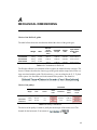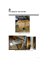
1
Tomas Andreasen Haviernik
PLC-control
with Electrical Motors
Model of an automated warehouse with
multidimensional movement
Bachelor 's Thesis, April 2009
Tomas Andreasen Haviernik
PLC-control with Electrical Motors
Model of an automated warehouse with
multidimensional movement
Bachelor 's Thesis, April 2009
PLC-control with Electrical Motors, Model of an automated warehouse with multidimensional movement
The report has been prepared by:
Tomas Andreasen Haviernik
Supervisor(s):
Nils Axel Andersen
Ole Ravn
DTU Electrical Engineering
Automation and Control
Technical University of Denmark
Elektrovej
Building 326
DK-2800 Kgs. Lyngby
Denmark
www.elektro.dtu.dk/English/research/au.aspx
Tel: (+45) 45 25 35 50
Fax: (+45) 45 88 12 95
Date of publishing:
20. april 2009
Classification:
1 (offentlig)
Comments:
This report is part of the requirements to achieve Bachelor of
Engineering at Technical University of Denmark.
The report represents 15 ECTS points.
Copyrights:
2
© Tomas Andreasen Haviernik, 2009
ABSTRACT
The report describes the basic design concepts for the PLC controlled motion systems.
This is done through the building a model of an automated warehouse. The main goal
was not to introduce a scalable solution for the industrial use but to build the system that
would serve educational purposes. The work includes a wide range of problems starting
with mechanical design, integrating the electrical design as well as introducing the concepts of the software design for the PLC motion control.
3
TABLE OF CONTENT
Abstract ........................................................................................................................... 3 List of figures................................................................................................................... 7 List of tables .................................................................................................................... 9 1 Introduction ........................................................................................................... 13 1.1 Background ...................................................................................................... 13 1.2 Problem formulation ........................................................................................ 13 1.3 Work by others................................................................................................. 14 2 Overview of the design and analyses ................................................................... 15 2.1 Basic components of the design....................................................................... 15 2.2 Design analyses................................................................................................ 18 3 Mechanical design ................................................................................................. 21 3.1 The design concept and assembly parts ........................................................... 21 3.2 Implementation ................................................................................................ 25 3.3 Results and possible improvements ................................................................. 26 4 Electrical design..................................................................................................... 28 4.1 Technology of PLC controlled motion ............................................................ 28 4.2 Design and implementation ............................................................................. 31 4.3 Results and possible improvements ................................................................. 34 5 Software design...................................................................................................... 37 5.1 Concepts, tools and theory ............................................................................... 37 5.2 Implementation ................................................................................................ 40 5.3 Results and possible improvements ................................................................. 42 6 Conclusion.............................................................................................................. 43 6.1 Results .............................................................................................................. 43 6.2 Further work..................................................................................................... 43 5
Table of content
Literature .......................................................................................................................47 A Mechanical Dimensioning .........................................................................................49 B Pictures of the system ................................................................................................51 C Wiring .........................................................................................................................53 D Servo Driver Parameters ..........................................................................................57 E DC541 modul..............................................................................................................63 6
LIST OF FIGURES
Figure 2-1: Concept of the Servo Driver R88D-UP ...................................................... 17 Figure 2-2: Motor torque ............................................................................................... 17 Figure 2-3: Mechanical concept .................................................................................... 19 Figure 3-4: DryLin N guide........................................................................................... 21 Figure 3-5: Iglide Clip Bearings and DryLin guides ..................................................... 22 Figure 3-6: Assembly parts............................................................................................ 22 Figure 3-7: Z movement platform ................................................................................. 23 Figure 3-8: Concept for the X and the Y motion........................................................... 24 Figure 3-9: Points of design deviations ......................................................................... 26 Figure 4-10: Homing ..................................................................................................... 30 Figure 4-11: Servo system............................................................................................. 32 Figure 4-12: H-bridge .................................................................................................... 33 Figure 4-13: Test flowchart ........................................................................................... 34 Figure 4-14: Performance of the X motor ..................................................................... 35 Figure 4-15: Performance of the Y motor ..................................................................... 36 Figure 5-16: DC541_FREQ_OUT Function Block....................................................... 37 Figure 5-17: Concept of PLCopen Motion Control Libraries ....................................... 38 Figure 5-18: PLCopen state diagram............................................................................. 39 Figure 5-19: Function Block for IO comunication ........................................................ 40 Figure 5-20: Function Block for relative movement ..................................................... 41 Figure 5-21: Test program............................................................................................. 41 7
LIST OF TABLES
Table 2-1: PM571 CPU ................................................................................................. 15 Table 2-2: Motor data .................................................................................................... 18 Table 3-3: Data for DryLin N guides............................................................................. 22 Table 3-4: Mechanical assembly parts........................................................................... 25 Table 3-5: Comparison of estimated and measured torque values ................................ 27 Table 4-6: Comparison of DC541 and CD522 .............................................................. 32 9
11
1
INTRODUCTION
High resolution position control has been many years the domain of high speed microprocessors because of their ability to process high frequency signals from encoders. But
in the last decade most Programmable Logic Controller1 producers have introduced new
options for motion control by integrating high speed counter units. These units are able
to sample high frequency signals and generate Pulse Width Modulated 2 signals or a
pulse train. This feature extends the application field of the PLC technology.
1.1
Background
The automated warehouse is a project with focus on PLC controlled motion and has
been designed to serve the educational purposes. The main objective is to build a system, which would be able to pick a quadratic object of specified weight, 1kg, from a
shelf and unload it at the specified place. The size of the object is specified to be
roughly 20cm x 11cm x 7 cm. The model will be build around an ABB PLC unit and
Omron servo driver units with servomotors, the hardware currently owned by the institute.
1.2
Problem formulation
The assignment consists of a few stages: a mechanical design, electrical design and interface and a test program for position control. Each of these parts contain a set of problems that should be solved with respect to each other as some of the problems are related to the mechanical design as well as to the electrical design.
The problems:
• designing a model and dimensioning design for the motors available
• building a model
• interfacing of the PLC units with the servo units
• testing the design by a simple program
1
2
PLC
PWM
13
Introduction
General requirements are:
• cost effectiveness
• simplicity of manufacturing
1.3
Work by others
Most of the manufacturing work for the mechanical part of the project was done by
Johnny Andreasen, my father-in-law and the special cables were manufactured by Bertil
Morelli from Automation and Control.
14
2
OVERVIEW OF THE DESIGN AND ANALYSES
This part of the report describes the considerations and the choices in designing the system. The model from the hardware point of view consists of two logically distinguishable parts, the mechanical and the electrical. It is important to look at the limitations of
these two parts separately but also in the context of interaction between each other. That
means that the mechanical part has to take account of limitations of the electrical and
vice versa.
2.1
Basic components of the design
The chapter describes the basic features of the components the design has been build
around. This is needed to understand the choices made in the further developing of the
design.
2.1.1
Programmable Logic Controller (PLC)
Program memory Flash EPROM and RAM PM571 64 kB SD Memory Card 21 kB, incl. 1 kB RETAIN 128 MB Cycle time for 1000 instructions Binary 0,3 ms Data memory, integrated Word 0,3 ms Floating point 6,0 ms Real‐time clock with battery back‐up YES Program execution cyclic YES time‐controlled YES multitasking YES Table 2-1: PM571 CPU
15
Overview of the design and analyses
The PLC used in the project is from the series AC500 from ABB. The Central Processing Unit 3 is of type PM571 and it has three Input/Output4 modules attached to it. Two
of them are DX522, digital relay IO modules and one analog IO module, AX522. The
software package for programming includes the CoDeSys v2.3 suite, which implements
IEC-6113 compliant languages for programming the system. These include Instruction
List5, Structured Text6, Ladder Diagram7, Function Block Diagram8 and Sequential
Function Chart9.
2.1.2
Servo Driver R88D-UP
R88D-UP is a programmable servo drive from Omron that uses pulse-train input signals
for position control and indexing for speed control. There are four possible choices for
the control modes:
• Position Control
This mode uses pulse-train input signals as a position and speed command. Numbers of pulses are used as the position reference and frequency as the speed reference.
• Position Control with Pulse Stop Input Enabled
Works with the same principle as the previous mode but implements a signal that
prevents the driver from reading the impulse during position control.
• Internal Speed Control Settings
In this mode the speed can be changed to one of the 3 preset values.
• Internal Speed Control Setting + Position Control
This mode implements position command and Internal Speed Control.
The servo driver is programmed from a PC with the WMON Win 1.110 programming
software, which can be also used for online monitoring. Desired configuration is created
by setting of the parameters in User Parameter window of WMON Win and uploaded to
the servo driver. There are two 8 bit parameters, Cn-01 and Cn-02, that are used for
choosing one of the control modes mentioned previously and the rest of the parameters
have form of integers and are used as parameters for a control loop of the driver.
3
CPU
IO
5
IL
6
ST
7
LD
8
FBD
9
SFC
10
WMON
4
16
Overview of the design and analyses
Figure 2-1: Concept of the Servo Driver R88D-UP
Figure 2-1 shows the principle of the control in the driver and some of the parameters.
For all parameters and wiring see Appendix C.
2.1.3
200 VAC Motor with incremental encoder
The servomotor is of type R88-U05030VA-S111. It is a standard motor for the R88DUP03V12 servo driver. It is a motor without break and with encoder resolution of 2048
pulses.
Figure 2-2: Motor torque
11
12
Motor
Servo Driver
17
Overview of the design and analyses
Rated output 50W Rated torque 0,159 Nm Rated rota‐
tional speed 3000 r/min Momentary maximum torque 0,48 Nm Weight 400 g Default reso‐
lution of the system 2048 pulses/rotation
Table 2-2: Motor data
Figure 2-2 shows the relation between velocity and torque of the motor and Table 2-2
shows the specifications relevant for designing the system.
2.2
Design analyses
The goal of the project is to build a system that can move an object from a shelf and
unload it at specified place. For each part of the project there are problems to be solved.
The following chapters describe the problems to be solved and the basics of the chosen
concepts.
2.2.1
Mechanical system
The objective is to build a mechanical construction that is able to move in three perpendicular directions, X,Y,Z. This part of the design is very time-demanding in manufacturing, so simplicity is crucial for the design. That’s why the concept should consist of
as few parts as possible and they all should be relatively cheap. Other things to consider
are:
• weight of the different parts
• placement of the parts in relation to the movement
• motors have to be able to work with the load
• the guides should be able to function with the forces applied on them
• size of the pulleys should be related to the speed and the maximum torque of the
motors
Figure 2-3 shows a concept like that.
18
Z
Overview of the design and analyses
X
Figure 2-3: Mechanical concept
This concept would allow movement in all directions, while the bearing construction
would be made of linear guides. Other concepts were considered, but most of them included one or more parallel mounted linear guides.
2.2.2
Electrical system
The challenge of the electrical design is in the motor control and interfacing. The simplest solution for movement in XYZ plane is to use 3 independent motors. For the mechanical design considered in the previous chapter can be concluded that the movement
in the X and the Y direction is dependent on the length of travel to the shelf to be emptied, while the movement in the Z direction is of a fixed distance. The Z movement
could be carried out by a simple DC motor of smaller size that would react to two microswitches as the position sensors for two positions “in the shelf” and “out”. This configuration would be also convenient from the mechanical point of view, since the Omron motors are of a considerable weight and the cables used for controlling the motors
are also quite thick and heavy. The X and the Y movement would be implemented with
the Omron system.
19
3
MECHANICAL DESIGN
This chapter describes the considerations behind the design of mechanical structure of
the system. It is related to the electrical design mainly through the limitations of the
motors.
3.1
The design concept and assembly parts
The following subchapters describe the assembly of the parts and the concept for the
three axis movement.
3.1.1
Assembly parts
The mechanical construction is build around products from Igus, a company producing
polymer bearings and guides, and timing belts with corresponding pulleys from a supplier Bondy A/S.
A linear guide series Drylin N is a relatively cheap and solid solution for linear movement that consists of an aluminium rail and a carriage coated with a special plastic with
a low friction coefficient.
The picture bellow shows Drylin N guide and the limits for the forces to be applied on
the guide. Table 3-3 shows the data for all 4 versions of the guide using the same plane
orientation as Figure 3-4.
Figure 3-4: DryLin N guide
21
Mechanical design
Type Width of rail N17 N27 N40 N80 17 mm 27 mm 40 mm 80 mm Fy 50 N 500 N 700 N 1000 N Fz 50 N 500 N 700 N 1000 N Mx Nm 5 Nm 10 Nm 32 Nm My, Mz Nm 3 Nm 6 Nm 15 Nm Table 3-3: Data for DryLin N guides
Axis bearings are of type Iglide Clip Bearings, also a product from Igus. See Figure 3-5.
Figure 3-5: Iglide Clip Bearings and DryLin guides
For transforming the rotational movement to the linear movement a system of timing
belts was used. The belts and the pulleys were chosen from the Bondy A/S catalogue.
Another frequently used assembly part in the design is made of a quadratic aluminium
profile. This part is mounted at the ends of the Drylin guides and is used either to carry
the axes for the pulleys or to carry a motor. The size was chosen to satisfy all axis
movements as this was the most efficient solution. The profiles mounted to carry the
pulleys have a long mounting slot, so it would be possible to tighten the timing belt.
Figure 3-6: Assembly parts
22
Mechanical design
3.1.2
Concept for Z movement
The movement in and out of the shelf, the Z movement was designed as illustrated in
the Figure 3-7.
Y
X
Figure 3-7: Z movement platform
The blue painted parts are in a higher plane and consist of the rail and the timing belt for
the X movement and the red parts are also in a higher plane but are the rail and the motor for Y movement, up and down.
Motor is placed under a little platform supporting a guide rail at the end closer to the
shelf. The motor will be smaller and lighter than for the other two axes, keeping the
weight of platform lower. The fork is mounted to the carriage and is moved by a timing
belt in and out of the shelf.
For dimensions see chapter 3.1.4 and Appendix A.
3.1.3
Concept for X and Y movement
Figure 3-8 shows the concept of X and Y axes motion apparatus. It is a frontal view and
the guide rail for X movement is mounted on the top of the shelf. Both motions are implemented with a timing belt pulled by an AC motor. For both motions, one pulley is
mounted directly on the motor axis and the other pulley is mounted in the quadratic profile illustrated on the Figure 3-6 in chapter 3.1.1.
The illustration shows clearly placement of the Z motor.
23
Mechanical design
Figure 3-8: Concept for the X and the Y motion
3.1.4
Dimensioning and choice of components
The dimensions of assembly parts were chosen by a qualified guess, based on some
simplified calculation models.
Friction coefficient of the guides is not listed in the manual, so relatively high friction
coefficient of 0,4 was chosen. The weight of the object used in calculations is 1 kg, Z
platform was estimated to be 1,5 kg and the weight of the construction pulled by motor
X was estimated to be 2,5 kg.
• Choice of Drylin N guide dimensions
The length was chosen to satisfy the dimensions of the shelf. The type of the guide
was chosen by calculating the torque that is applied on the carriage, by multiplying
the estimated center of mass distance with the estimated weight of the object
mounted on the carriage.
• Choice of timing belts
Type of the timing belts were chosen in respect to their maximum allowable tensile
load. The choice was made by estimating the load. The length was chosen to satisfy
the dimensions of the shelf and the guides.
• Choice of pulleys
The pulleys were chosen with respect to the rated torque of the motors and the
maximum torque of the motors, while taking to consideration the speed of the linear
movement. It should be noted here, that a change of an electronic component caused
24
Mechanical design
lower possible Revolutions Per Minute13 value for the motors and therefore the
choice of the pulleys was based on the limit values of the rated torque of the motors.
See chapter 2.1.3 for the torque data.
Axis Drylin N type Z N27 X N27 Y N40 length 330 mm 1000 mm 750 mm width Timing belt type 27 mm T2,5 Synchroflex 27 mm T2,5 Breco V 40 mm T2,5 Synchroflex length 6500 mm 2010 mm 1475 mm width 6 mm 10 mm 10 mm max load 65 N 49 N 117 N Pulley type T2,5 T2,5 T2,5 diameter 12,20 mm 28,15 mm 19,35 mm number of teeth 16 36 25 Table 3-4: Mechanical assembly parts
Table 3-4 shows the choices for the components. For the speed of the movement in
Revolutions Per Second14 applies:
Considering performance of the electronic system without using electronic gearing, the
maximum rotational speed for the motors is 1,22 RPS. With 2,5 mm teeth this would
give 7,6 cm/s for the Y movement and 10,8 cm/s for the X movement. The default resolution can be calculated by dividing the length of travel per rotation with 2048. The detailed calculations for the choice of the guides and the pulleys are included in
Appendix A.
3.2
Implementation
The implementation of the concepts introduced in the previous sections was slightly
modified. The reason for this was that static friction of the carriages was higher than
previously expected. The maximum moment rates for the carriages seem to characterise
the maximum load before the carriage brakes rather than the maximum load for the car13
14
RPM
RPS
25
Mechanical design
riage to fulfil its function, allowing the movement of the objects mounted to it. When
implementing the desired configuration, the friction at carriages for the X and the Y
movement caused vibrations even at very slow motion.
100,00
75,00
18,00
5
3
18,50
1
4
2
Figure 3-9: Points of design deviations
Figure 3-9 illustrates the regions of the changes made. The major changes were implemented because of too high static friction at the point “1” and the point “4”. The carriages for respectively X and Y movement. The solution was to spread the friction between two carriages, so an extra carriage was inserted into both rails. This caused a
slight increase in the weight especially in the vertical movement, Y, as the carriage uses
an aluminium quadratic bar to carry the Z platform. The bar became roughly 10 cm
longer adding roughly 100 g to the construction. For the X movement an extra guiding
wheel was mounted. The guiding wheel is placed on the bottom of the vertical Y guide,
point “2” and follows an aluminium plate mounted at the bottom edge of the shelf, point
“3”. For the pictures of the details see Appendix B.
3.3
Results and possible improvements
The system was tested by a spring scale. The spring scale was applied closest possible
to the points where the timing belts are mounted to the carriages. The force needed to
move the fully loaded carriage was measured by pulling the scale in desired speed.
The force needed to move in the X direction was measured to be roughly 1 kg while
trying to maintain desired constant speed. The force in the Y direction was measured to
be roughly 2,1 kg and in the Z direction roughly 0,3 kg.
26
Mechanical design
Measured Estimated Torque Measured Force Torque applied on the motor Sugested Radius for Pulley 0,142 Nm 20,58 0,199 Nm 7,73 mm 0,138 Nm 10,78 0,152 Nm 0,026 Nm 2,94 0,018 Nm Table 3-5: Comparison of estimated and measured torque values
The Table 3-5 shows, that the measured forces are slightly higher than expected. This is
not as problematic for the horizontal movement as for the vertical. The rated torque of
the motor is the torque that the system is able to maintain in longer periods. The Y motor will have to hold the object to be carried in unspecified period of time. The mechanical solution to this would be choosing a smaller pulley, lighter Z motor and trying
to use lighter construction parts. For maintaining the speed, possible solutions are part
of the electrical design.
27
Electrical design
4
ELECTRICAL DESIGN
Electrical system consists of PLC, servo drives and motors. This part of the report gives
an account on the theory behind the electrical design, design itself and the testing of the
system.
4.1
Technology of PLC controlled motion
There are many concepts for controlling the motion with PLC and the choice of the
concept is very much application dependent. Motion control usually means controlling
position, speed or torque of a motor but most of the systems from logical reasons combine all three possibilities of control. For the purpose of this project, it would be convenient to focus on position control systems. Most common methods used in praxis are:
• Systems with limit switches
This method is usually used for the applications that require less precision and can
be very cost effective if the number of required position is limited. The principle is
that switches are used to time the deceleration of the movement and stopping.
• Step motors
Step motors are relatively small, so the range of the application is very limited. Precision is lower in high speed.
• DC servo systems
Because of the brushed DC motors, these systems require maintenance, changing
the brushes. They also tend to be less accurate in higher velocities.
• General purpose inverters
Inverters are being used for application where control of torque and speed is more
important than position control. They are very often used to control blending machines in industrial processes.
• AC servo systems
AC servo systems are most common choice for the modern systems that require
higher precision for positioning and high power.
(Mitsubishi, p.2-4, chapter 1, 2000)
28
Electrical design
4.1.1
Concepts of PLC motion control
There are few possibilities how to configure a motion control system when using PLC.
The choice is very much dependent on complexity of the movements to be controlled.
Following are the decisions to be made when designing a motion control system:
1. Open-loop and closed-loop control
Open-loop control is usually implemented for the systems with negligible disturbances on the process variable. (Erickson, p.769, 2005) Obviously, this choice application dependent, and especially for the position control the closed loop is the
first choice. Considering that even a system based on switches or discrete sensors is
considered to be a closed loop system, there is undoubtedly very few reasons to implement an open-loop control.
2. How to close the loop
When considered systems with closed-loop control, usually the question is how to
process the feedback. Considering a system that consists of a controller, can be CPU
or a motion controller, a driver and a motor, a lot of the systems today offer a default configuration examples by closing the loop in the drive. This is possible because the control itself is usually processed in a so called servo driver. The controller generates the speed or the position command and uses only a conformation signal that the command has been carried out. Additionally, the new servo drivers have
also a communication interface, which allows the controller to access their data. If
this is not the case, and the motion needs more than just a position conformation, the
next point has to be addressed.
3. System with or without a motion controller
Most of the PLC brands today implement high frequency pulse functionality to their
systems. Usually it is a module capable of reading and writing high frequent digital
signals. This functionality has opened up possibilities to cheaper solutions if the
complexity of the movement is lower, because most of the servo drivers today require these signals as a reference for velocity and position.
But for the motion that is more complex in the context of synchronising and coordination, motion controllers are a necessary part of the system.
4.1.2
Homing methods with an incremental encoder
Homing is a procedure that assigns position to a reference point. Because of the incremental encoders used for the system, following chapter describes the most frequent
methods for homing or as it is sometimes called “the origin search”. There are three
common methods for homing:
• Absolute switch homing
The principle of this method is to search for “Off-On-Off” signal from a sensor. The
method is illustrated on the Figure 4-10.
• Limit switch homing
29
Electrical design
In this method the search for “On” signal of a limit switch is performed. Direction of
the movement is dependent on the position of the object.
• Homing against physical object
This method is performed by searching a physical obstacle. The method requires
torque limits for the motor.
• Homing with a reference signal Z
This method can be combined with an absolute switch or a limit switch. It implements so called Z signal from the encoder. The signal is generated once for a rotation. Searching for a switch is performed and when the switch is active, movement
continues, usually with very low speed, until the next Z pulse. This method is used
for high precision systems as switches might respond with slightly different delay.
(PLCopen, Part 5, p.4-8, 2006)
Figure 4-10: Homing
The common practice is to perform search first by higher speed and when the switch is
found, the speed is lowered and the search is performed once again. This applies of
course for the methods that use switches.
30
Electrical design
4.2
Design and implementation
Design consideration follow three main lines of thought. Besides economy and simplicity as previously mentioned in the requirements, the design was also build to demonstrate some of the standard solutions for PLC motion control. The system consists of
two AC servo drivers controlled by PLC that drive the X and Y axis and one smaller
motor that could drive Z axis.
4.2.1
X and Y axis control
For interfacing the servo driver and the PLC, the suitable interfacing module had to be
found. The first design concept was created around the CD522 Encoder and PWM
module. Unfortunately despite the fact that the product was announced to be in sale already in the end of 2008 and was offered by ABB technical support stuff, the module
will not be available before summer 2009.
CD522 Encoder and PWM module
This is an expansion module for the PLC dedicated to interfacing with motion servo
systems. The manual can be found on the CD. This module can process RS-422 encoder signals that are used in the Omron servo. It has two high frequency outputs with a
maximum frequency of 15 kHz.
DC541-CM Interrupt and Counter Module
DC541 is a configurable I/O module that can be configured as an interrupt module or a
counter module. The modes are mutually exclusive.
The module has 8 channels that can be configured as inputs or outputs. When configured as a high-speed counter, the module can process 24V input or output signals. For
the design purposes of this project, the functionality of so called “Frequency output”
mode is the most interesting one. In this mode all 8 channels can be configured as frequency outputs at max. 2,5 kHz. All functions are implemented through the set of Function Blocks that are part of the AC500 software library. For more details about DC541
see Appendix E.
While CD522 module would make it possible to track the position of the physical system, the module DC541 is only capable to provide the command impulse. The table
bellow shows the differences in features of the modules that has the biggest impact on
the design.
31
Electrical design
CD522 DC541‐CM Number of high fre‐
quency outputs 2 8 Max frequency of the outputs 15 kHz 2,5 kHz Supports RS‐422 com‐
patible encoder signals for the counter inputs (A,B,Z) JA (two encoders) NO Table 4-6: Comparison of DC541 and CD522
This means that after each abortion of position command the system will have to perform the origin search. This is partly caused also by the library used for DC541-CM.
The FB that controls output signal does not keep track of the pulses already sent before
the stop. Without knowing how many pulses have been sent before the abort, the only
solution is to do homing procedure. The system for X and Y axis looks as illustrated in
the Figure 4-11.
Figure 4-11: Servo system
Interfacing
Communication between the PLC and the servo driver is based on a command signal
from PLC, direction signal and pulse train for position and speed, and conformation of
successful positioning. The signal that confirms successful positioning should be adjusted in PLC code, because it goes high every time the motor reaches the referenced
position, or even if the frequency of the command word is too low. This might be a
problem with higher integration times for the controller settings or with slow motion for
homing procedures. The extra flag with a delay could be used to solve this. The signal is
called INP, in position15. Other signals include ALM, alarm from the servo driver,
RESET, resets the alarm, ECRST, resets the deviation counter and RUN, turns on the
servo driver. The interface of the servo is based on sourcing inputs and sinking outputs
which had to be solved with passing the zero reference by relay outputs to the driver’s
inputs and by pull up resistors when for the drivers sinking outputs.
15
INP
32
Electrical design
Homing
For the homing procedure the microswitches has been installed. They are placed as limit
switches on the guide for the X movement and for the Y movement one microswitch
was installed at the top end. The servo driver has protection for overload, so limit
switches serve very little purpose. Because every abortion of movement would lead to
the homing procedure, the limits for the movement should be software defined.
4.2.2
Z axis control
The Z axis control was implemented only on the mechanical level, but the concept for
electrical implementation was designed. For Z axis movement a smaller DC motor
should be chosen. By choosing a smaller motor for Z axis, the weight of the construction could be lowered, new concept of motion control introduced and the solution would
be also more economically efficient. Considering that the Z axis needs to recognise only
two positions, “In” and “Out”, a control based on limit switches should be sufficient.
The motor A-max-22 from Maxon was mounted on the platform for Z movement together with the microswitches, but the performance of the motor was not verified. It is
equipped with a planetary gearhead that rates the continues torque to 0,8 Nm. The control can be implemented with a typical H-bridge configuration consisting of two 3Pole
Double Throw16 relays controlled from the PLC. An extra pole would be used to avoid
activating forward and backward movement at the same time. It would turn off the control signal for the opposite direction when activated. An extra power supply would be
required, as the supply used for the PLC has no sufficient current rates and using the
same power supply for the control signals and the actuators is a bad design practice.
Figure 4-12 shows the control concept for Z movement. Details for wiring of the system
are part of Appendix C.
Figure 4-12: H-bridge
16
3PDT
33
Electrical design
4.3
Results and possible improvements
The system was tested by a simple program that with help of a few push buttons moved
in the desired direction. The functionality of the installation was in this way verified
indirectly. The performance of the motion functionality was tested by WMON software
for the servo driver. The software can monitor motor behaviour in the desired period of
time and then it generates a graph by spreading the time period over 1000 points. The
test period in the both illustrated cases was 50 seconds so the graphs have a vertical grid
of 2,5 seconds. The flow of the test was as follows:
MOVE WITHOUT A LOAD
2500 pps motion command(MAX)
Factory settings for the controller
ADJUST
CONTROLLER
NO
PERFORMED
WELL?
YES
TEST WITH
THE FULL
LOAD
ADJUST
CONTROLLER
NO
PERFORMED
WELL?
YES
END OF
TEST
Figure 4-13: Test flowchart
4.3.1
Test of the X axis motion
When testing the X axis motion the few settings in the servo driver were changed due to
performance issues. The movement suffers of a high static friction and high acceleration
causes strong vibrations in the mechanical system. The adjustments of the controller
included a higher integration constant, using an acceleration and deceleration functionality of the servo driver and using a special bias function that increases the speed when
the position deviation is too little. This helped to suppress the swinging caused by a
higher integration constant. The detailed settings for controller can be found in the Appendix D.
The Figure 4-14 shows the test with the adjusted settings. The graph shows two running
of the axis. In both cases the travel distance was 5000 pulses, which is roughly 22 cm.
34
Electrical design
The first curve describes the motion with full load. The vibrations of the system caused
by the static friction are clearly recognisable. The second curve shows a run was without the load.
Figure 4-14: Performance of the X motor
4.3.2
Test of the Y axis motion
The Y axis motion was tested first with a full load, but the system would turn off after
20 seconds. This is caused by the protective function of the servo system, which turns of
the motor if the torque of the load exceeds the rated torque of the motor with 20% in
more than 20 seconds. The system was tested with 820g. This weight showed a stable
continues torque. If the weight was higher, the torque needed to maintain the vertical
position would differ from time to time considerably with the same load applied.
The FigureXX shows the test run with 820g. The tests were done by moving 5000
pulses, roughly 15 cm, and with full processing speed of DC541, 2500 pps, roughly 7,6
cm/s. The graph in the Figure 4-15 shows clearly that the vertical movement up caused
some vibrations.
35
Electrical design
Figure 4-15: Performance of the Y motor
4.3.3
Improvements
The results of the test show that the momentary torque of the motors is sufficient for the
system, but the continuous torque is slightly lower than needed. The system has also
tendency to vibrate, but this could be improved by tuning the controller and finding
ideal values for acceleration and deceleration, integration constant and position gain.
36
5
SOFTWARE DESIGN
This chapter describes the software part of the project. This includes some standard libraries used for the project, as well as the library developed for the control of the motor
and a short test program.
5.1
Concepts, tools and theory
5.1.1
PS501 Control Builder
PS501 Control Builder is a standard software package for AC500 programming. It includes programming software CoDeSys V2.3 as well the tools for configuration of network and OPC client.
5.1.2
DC541 Library
DC541_AC_500_V11.lib is a function block library that is used to implement the different modes of DC541-Interrupt and Counter Module. The library is installed automatically after adding the unit into PLC configuration.
Figure 5-16: DC541_FREQ_OUT Function Block
The library contents a number of function blocks used for different configurations of
DC541. Figure 5-16 shows the function block used for generating a pulse-train signal.
37
Software design
There are few other configuration function blocks that should be added to a program for
DC541 to function. For the details, see Appendix E.
5.1.3
PLCopen Motion Control Libraries.
PLCopen is an independent association for industrial suppliers and users. It was
founded in 1992 with the main objective to promote usage of the IEC 6113-3 standard.
The objective later changed from the promotional to supplementary work and through
its so called “task committees”, they actively work on creating guidelines for the automation standards.
“PLCopen Motion Control Libraries” is a programming standard that describes the
guidelines for developing libraries for motion control based on IEC 6113-3 function
blocks (FB) definitions. The main purpose of this standard is to unify the programming
interface for motion control and that way to improve compatibility of different systems
and shorten time for developing motion control applications.
This project uses the standard as an inspiration for building the FBs that interface with
the previously described hardware. The FB’s are not compliant with the standard. It
rather copies the concept of the standard, where some simple FBs interfere with hardware through a structure variable.
Basic principles of the standard
The standard is build around a number of function blocs that each carries on a certain
operation on the axes to be controlled. This way the FBs can be arranged as a flowchart
passing the state of the axis and the needed information through obligatory input
AXIS_REF. AXIS_REF is a structure that keeps track of the movement. The principle
is illustrated in the Figure 5-17.
Figure 5-17: Concept of PLCopen Motion Control Libraries
38
Software design
The FBs and AXIS_REF are hardware dependable, so the standard gives just some outlines for the functionality. The operations are carried out sequentially and the standard
describes the states of the axis and the transition conditions. “A change of state is reflected “immediately” when issuing the corresponding motion command. (Note; the
response time of “immediately” is system dependent, coupled to the state of the axis, or
an abstraction layer in the software)” (PLCopen v 1.1, 2005, p.13)
The behaviour of the system when more blocks are active at the same time is also described in the standard and there is given an encounter on the possible configurations.
The code for these function blocks is not accessible for the user. The figure bellow
shows the state diagram for the single axis motion libraries with the corresponding FBs.
The whole series of the publication can be found of the CD.
Figure 5-18: PLCopen state diagram
39
Software design
5.2
Implementation
To implement the test program, the concept of the PLCopen Motion Control Libraries
was adopted. The program is implemented by two tasks, one taking care of communication with inputs and outputs and the other carries out the operations of the desired motion profile. The tasks interfere through the structures that represent the axis. The axis
can recognise only two states, Standstill and Discrete motion.
5.2.1
Function Blocks and the AXIS_REF structure
For the purpose of the test program some simple FBs were developed. They were designed as a possible concept for the further work on the system and can be reused as a
library. The code is written in ST.
Figure 5-19: Function Block for IO comunication
Axes_COM is the FB that carries out the I/O tasks. The FB might be a little confusing,
because some inputs actually interface with the outputs through the DC541 library FBs
placed in the Axes_Com FB. These include the number of slot, the number of channel
for the pulse train, the number of channel for the direction signal and the number of
channel for the deviation counter reset. The rest of the inputs are the inputs to the system and the outputs are as well outputs to the servo driver. The structure Axis is a global
variable of type AXES_REF, which passes control signals for the corresponding motor
between the instances of the program.
40
Software design
Figure 5-20: Function Block for relative movement
The FB MC_MoveRelative has a very simple functionality. It takes INOUT Axis structure as the input. With a rising edge of the Execute input new values are passed to the
Axes_COM block through the Axis structure and the state of the axes is changed to
Discrete Motion. When the falling edge of “In Position”17 signal is detected, the State is
changed to the Standingstill and the output Done goes “high”.
AXES_REF is the structure of type VAR_IN_OUT that contains the data representing
the axes to be controlled. In the design only a few of the structure members were used,
but the definition was made to satisfy also possible use in the future. The structure in
this program is used to pass the values for the speed and the distance of travel, but also
for changing the state and passing the INP signal.
5.2.2
Test program
The program itself is of a very simple structure. There are two instances of AXIS_REF,
Axis1, representing the X movement, and Axis2, representing the Y movement. The
main task PLC_PRG(PRG) can be seen in the Figure 5-21.
Figure 5-21: Test program
It is executed with a period of 5 ms. The movement is controlled by push buttons
“push” and “push1”. The flow of the program is quite easy to follow from the picture.
When the button “push” is activated, FBs “X_direction” and “Y_direction” are
17
INP
41
Software design
executed, when they finnish the execution, pushing the button “push1” activates
“backXdir” and the Axis1 returns to the start position.
The other task, COM(PRG), the one that takes care of the hardware interfacing, is
executed with a perion of 4 ms and has higher priority than the main task. It includes
two FBs of the type Axes_COM that represent the axes X and Y.
5.3
Results and possible improvements
The program was tested and showed slightly unstable behaviour when two motion FBs
were connected the way that the signal Done from the first FB was triggering the Execute of the next FB. It would than stay in the state Discrete Motion. The reason to this is
the fact that the movement is triggered by the rising edge on the Start input to the
DC541 FB. If the program leaves the Standstill state very quickly, the COM does not
restart the Start signal. The solution to this could be to increasing the execution period
of the main task or introducing a delay to the state machine. Decreasing the period time
for COM task could cause some problems, as it was observed that the tasks maximum
period reached 3,3 ms. The test program can be found on the CD.
42
6
CONCLUSION
Working on the project has been a very satisfactory experience. It has also brought
some challenges. Combining concepts of mechanical, electrical and software design into
one application requires constant considerations of the impacts the change in one concept would mean for the rest of the system. The wide range of the problems to be solved
made the work very time consuming but also more interesting.
6.1
Results
It can be concluded that the most of the goals were achieved with satisfactory results.
The mechanical design introduced some challenges because of the time limitation.
Many parts of the construction are heavier than expected due to the limited choice of
material available at the time.
The electrical design has been implemented with slight changes because of the delivery
problems. The only part missing is implementing the control of the Z movement. But
the concept has been designed and the motor Z and the microswitches to control it are
mounted on the system. The biggest challenge of the electrical design was getting to
know the hardware and the software used in the project and interfacing sinking outputs
and sourcing inputs of the servo driver. The system was tested with a small program and
the concept for the structure of motion software introduced. Testing of the system
showed that it is capable of handling loads up to 820g.
6.2
Further work
The Z movement could be implemented as described in the report. If the object to be
lifted should be more than 820 g, the construction of the Z platform could be made from
lighter aluminium profiles and the pulley Y can be replaced by a slightly smaller one.
This would reduce the torque applied on the motor. To maintain the speed the electronic
gearing can be used. It would reduce the precision of the movement, but the system can
perform with much lower precision and still satisfy the application need. With a perspective to implement the full functionality of the system, the code should be written to
satisfy the application requirements. The concept introduced in the software part can be
43
Conclusion
used, as this would make the system flexible to the changes in the motion profiles. Developing a standard library for the hardware configuration would give the students possibility to focus more on the structuring of the application and understanding the typical
problems the PLC programmers are facing in the working process.
44
45
LITERATURE
OMRON (1994). User’s Manual,Omnuc U series, Models R88M-U (AC Servomotors),
Models R88D-UP (AC Servo Drivers)
OMRON (2000) User’s Manual,Omnuc W series / U series, Servo Driver/Servomotor,
Computer Monitor Software WMON Win Ver1.01
ABB (2007) DC541 Function Block Library, AC500 Software Description,
ABB (2006) System Technology of the DC541-CM Module, System Description
ABB (2007) AC500 Hardware, V2, System Description
Erickson, K. T. (2005), Programmable Logic Controllers: An emphasis on design and
application, Dogwood Valley Press
Mitsubishi Electric (2000), Programmable Controllers MELSEC-F, Positioning Controll, Training Manual
PLCopen (2005), Technical Specification, PLCopen Technical Commitee 2-Task Force,
Function Blocks for motion control, Version 1.1, http://www.plcopen.org/
PLCopen (2006), Technical Paper, PLCopen Technical Commitee 2-Task Force, Function Blocks for motion control: Part 5, Homing, Version 0.99,
http://www.plcopen.org/
McDaniel, C (2005), Motion Control System Choices, Automation Notebook, Issue 4,
Automation Direct, http://automationnotebook.com/
3S-Smart Software Solutions GmbH (2005), User Manual for PLC Programming with
CoDeSys 2.3
47
A
MECHANICAL DIMENSIONING
Choice of the DriLin N guides
The table bellow shows the consideration behind the choice of the guide types.
Weight Mass 1,40 kg 13,72 N 8,00 cm 1,098 Nm 6,000 Nm DryLin N 40, My 2,00 kg 19,60 N 15,00 cm 2,940 Nm 5,000 Nm DryLin N 27, Mx 1,10 kg 10,78 N 1,00 cm 0,108 Nm 2,500 Nm DryLin N 27, Mz Y movement X movement Z movement Distance to the center of mass Estimated Torque Torque limit Type and the torque direc‐
tion Table A-1: Calculations for DriLin N
The Weight collumn is an estimation of the weight to be mounted on the carriages. The
last two columns describes the chosen type of the guide and the torque limit for the carriage associated with the guide. The directions x,y,z are not related to the X, Y, Z plane
of the system. It is directions used in the manual of the product. The fomula is:
Choice of the pulleys
Estimated Weight Mass Friction Rated limits Max Radius Pulley Radius Estimated Torque Y movement 1,50 kg 14,70 N 0,4 (not used) 0,159 Nm 10,82 mm 9,68 mm 0,142 Nm X movement 2,50 kg 24,50 N 0,4 0,159 Nm 6,49 mm 14,08 mm 0,138 Nm Z movement 1,10 kg 10,78 N 0,4 N/A N/A 6,10 mm 0,026 Nm Table A-2: Pulleys calculations
The choice of the pulleys is made to justify the rated torque of the motors used. The
formula for the horisontal, Y movement is:
49
Mechanical Dimensioning
For the Y and Z movement:
Choice of the timing belts
The timing belts for the Z and the Y movement were the standard sizes. For the X
movement the following formula was used:
Where ”LB ” is the length of the belt, ”a” is a centre distance, ”zp ” is the number of
teeth of the pulley used and ”t” is a distance between the teeth. The centre distance for
the Y movement is 99 cm, so the belt length was chosen to be 210 cm.
50
B
PICTURES OF THE SYSTEM
Figure B-1: Picture of the system
Figure B-2: Picture of the modification on the Y axis
51
C
WIRING
The picture bellow shows the Servor Driver CN1 connector used for interfacing with
the PLC.
Figure C-1: CN1 connector
The PLC is connected to the hardware through terminal blocks of two colours, orange
and grey. They are numbered 1-20. Both colours are connected the same way to the
Servo Driver controlling the coresponding motor.
53
Wiring
The Table C-1 shows only the connection for the “grey” system controlling the axes X.
Terminal num‐
ber Servo X‐Axis (grey) 1 PLC Servo Remarks DC541 C0 (1.0) 1_+CW 1,5K resistor in series 2 0V 2_‐CW 3 DC541 C1 (1.1) 3_+CCW 1,5K resistor in series 4 0V 4_‐CCW 5 24V 13_24V 6 DX522_2 NO0 (3.0) 14_RUN Pull down input, R0=0V 7 DC541 C2 (1.2) 5_+ECRST 1,5K resistor in series 8 0V 6_‐ECRST 9 N/A 24_Z encoder 10 N/A 25_Z encoder DX522_2 I0 (1.0) 8_INP sinking output, 1,8K pull up resistor, see drawings 12 0V 10_OGND 13 DX522_2 NO1 (3.1) 18_Reset Pull down input, R1=0V 14 0V 35_ALMCOM 15 DX522_2 I1 (1.1) 34_Alarm sinking output, 1,8K pull up resistor, see drawings 16 GROUND 36_FG 17 DX522_2 I2 (1.2) CW_limit_switch 18 DX522_2 I3 (1.3) CCW_limit_switch 19 24V CW/CCW_switches 20 11 Table C-1: Wiring
The control signals to servo driver had to be implemented with a resistor in series with
the inputs on the terminals 1, 3 and 7. The size of the resistors is 1,5 kΩ.
The servo driver outputs INP and Alarm are sinking outputs and are connected following way:
54
Wiring
Servo Control
PLC
24V
Input
Gnd
1,8KΩ
Output
Gnd
Figure C-2: Pull up resistor
For the standard cables see the manual for the servo driver, Omron.pdf.
Figure C-3: PLC I/O configuration
The Figure C-3 shows the configuration of the signals in CoDeSys programming software on the PLC side.
55
Wiring
Figure C-4: Terminal Blocks
56
D
SERVO DRIVER PARAMETERS
The Figure D-1 shows the setting for the servo drivers when testing. It is a window of
the programming software for the Omron servo driver, WMON Win. The Y axis motion
used default settings for the controller parameters. The “Setup Parameters”, Cn-01 and
Cn-02 were the same for both axes. The parameters describe the mode of control as described in the chapter 2.1.2 of the report. When testing, the setup profile was made to
start the servo driver at the power plug-in and clearing of the deviation was also automatic. The values for Cn-01 and Cn-02 with the mentioned features were 08ED and
0480.
Figure D-1: Parameters for the X motor
57
Servo Driver Parameters
User Parameters from OMNUC U User’s Manual
• Speed Loop Gain: Cn-04
This is the proportional gain for the speed controller. The adjustable range is 1 to
2,000Hz (the response frequency when equivalent inertia is used). As the number is
increased, the gain is increased.
The factory setting is for 80 (Hz). Using the factory setting for the Servomotor alone or
with a small load inertia will cause vibration to occur, so set the value to a maximum of
20 (Hz) for operation.
• Speed Loop Integration Constant: Cn-05
This is the integration time for the speed controller. The adjustable range is 2 to 10,000
(ms), and it is factory set to 20 (ms). As the number is increased, the gain is decreased.
The unit can be changed using the integration time constant setting unit (Cn-02 bit Nob). (HA/LA/V/W Models)
• Emergency Stop Torque: Cn-06
When setup parameterCn-01 bit no. 8 = 1, this sets the braking torque for over-travel
stopping (forward/reverse drive prohibit input operation). The setting range is 0 to the
maximum torque (a percentage of the braking torque as 100% of the Servomotor rated
torque). The factory setting is for the maximum torque.
• Software Start Acceleration Time: Cn-07
Software Start Deceleration Time: Cn-23
The Servomotor rotation acceleration time from0 r/min to 4,500 r/min is set in Cn-07,
and the deceleration time from4,500 r/min to 0 r/min is set inCn-23. The factory setting
is for 0 (ms). Set the acceleration and deceleration times to 0 (ms) unless using the internal speed settings.
• Forward Torque Control: Cn-08
Reverse Torque Control: Cn-09
The Servomotor output torque control value for forward rotation is set in Cn-08, and the
value for reverse rotation is set inCn-09. The setting range is 0 to the maximum torque,
and the factory setting is for the maximum torque.
• Encoder Divider Rate: Cn-0A
The number of pulses detected (A- and B-pulses) per encoder revolution is converted to
the number of pulses set for this parameter and output from the Servo Driver. The setting range is 16 to 2,048 pulses/revolution, and the factory setting is for 1,000
(pulses/revolution).
• Rotational Speed for Servomotor Rotation Detection: Cn-0b
This sets the rotational speed for detecting whether or not the Servomotor is rotating.
The setting range is 1 to 4,500 r/min. When motor rotation detection has been set for the
sequence output signal switch (Cn-01 bit 4 = 0), the Servomotor rotation detection out-
58
Servo Driver Parameters
put (TGON:CN1-9) is turned ON if the Servomotor rotational speed meets or exceeds
this set value. The factory setting is for 20 (r/min).
• P Control Switching (Torque Command): Cn-0C
P Control Switching (Speed Command): Cn-0d
P Control Switching (Acceleration Command): Cn-0E
P Control Switching (Deviation Pulse): Cn-0F
These set the various points for switching the speed controller from PI control to P control in order to moderate excessive characteristics when an operation such as acceleration or deceleration is executed accompanied by output saturation of the controller.
These selections are made by setting the setup parameter Cn-01 bit nos. b, d and C.
• Jog Speed: Cn-10
This sets the speed for manual operation. The setting range is 0 to 4,500 r/min. During
manual operation, operating commands are given from the Parameter Unit. The factory
setting is for 500 (r/min).
• Number of Encoder Pulses: Cn-11
This sets the number of pulses per revolution of a connected encoder. Do not change
this parameter’s setting; the Servomotor might not operate correctly if it is changed. The
factory setting is for 2,048 (pulses/revolution).
• Brake Timing 1: Cn-12
Brake Command Speed: Cn-15
Brake Timing 2: Cn-16
These parameters determine the output timing of the brake interlock signal (BKIR),
which controls the electromagnetic brake.
Brake timing 1 sets the delay time from the time of brake interlock goes OFF until the
servo turns off. The setting range is 0 to 50 ( x10 ms), and the factory setting is for 0
(x 10 ms). The brake command speed is the speed (r/m) used to turn OFF the brake interlock. The setting range is 0 to 4,500 (r/m) and the factory setting is for 100 (r/m).
Brake timing 2 sets the wait time from when the servo goes OFF until the brake interlock goes OFF. The setting range is 10 to 100 (x10 ms), and the factory setting is for 50
(x10 ms).
If the run command turns off , a servo error occurs, or the main-circuit power supply
turns off during operation of a Servomotor with a brake, the dynamic brake comes on
(setup parameter Cn-01 bit no. 6 = 0) and Servomotor rotation speed is decreased.
When the speed drops to the level of the value set for the brake command speed (Cn15), the brake interlock output (BKIR: CN1-7) turns OFF.
Even if the speed does not drop to the level of the value set for the brake command
speed (Cn-15), the brake interlock output (BKIR: CN1-7) turns OFF after the time set
for brake timing 2 has elapsed. (This time setting is made for the purpose of preventing
damage to machinery or the Servomotor holding brake.)
• Torque Command Filter Time Constant: Cn-17
This sets the low-pass filter time constant for the torque command. The setting range is
0 to 250 (x100 µs), and the factory setting is 4 (x100 µs).
59
Servo Driver Parameters
The relationship between the filter time constant and the cut-off frequency can be found
by means of the following formula:
fc (Hz) = 1 / (2πT) : T= Filter time constant
If T= 400 (µs), fc will be approximately 400 (Hz).
When the characteristic vibration of the machinery is within the response frequency of
the servo loop, Servomotor vibration will occur. In order to prevent this sympathetic
vibration based on the characteristic vibration of the machinery, set the torque filter time
constant to a value that will eliminate the vibration(i.e., set it to a high value).
• Forward Rotation External Current Limit: Cn-18
Reverse Rotation External Current Limit: Cn-19
These set the Servomotor output torque limits for the forward and reverse directions.
They are valid when the forward/reverse current limits (PCL/NCL CN1-11/12) are input. This function can’t be used if the input command mode is set to “internal speed
control settings.” The setting range is 0 to the maximum torque, and the factory setting
is for the 100 (%).
• Position Loop Gain: Cn-1A
Adjust the position loop gain to the rigidity of themachine. Set to between 50 and 70
(1/s) for general NC machine tools, to between 30 and 50 (1/s) for general and assembly
machines, and to 10 to 30 (1/s) for industrial robots. Load alarms will be caused by machine oscillation if the position loop gain is increased for systems with low rigidity or
systems with intrinsically low-frequency vibration.
The setting range is 1 to 500 (1/s), and the factory setting is 40 (1/s).
• Positioning Completed Range: Cn-1b
This sets the deviation counter value for outputting the positioning completed output
(INP). When the deviation counter value falls below this setting, the positioning completed output turns ON. The setting range is 0 to 250 (command units), and the factory
setting is 3 (command units).
• Bias Rotational Speed: Cn-1C
This is the setting for position control bias. Use this setting according to the load conditions in order to shorten positioning time. The setting range is 1 to 450 (r/min), and the
factory setting is 0 (r/min).
• Feed-forward Amount: Cn-1d
This is the feed forward compensation for the position controller. Positioning time is
shortened by adding the command pulse differential to the speed command. The setting
range is 0 to 100%, and the factory setting is 0%.
• Deviation Counter Overflow Level: Cn-1E
This sets the level for detection deviation counter overflow. If the deviation counter
value exceeds this set value, a servo alarm will be generated. The setting range is 1 to
32,767 (x256 command units), and the factory setting is 1,024 (x256 command units).
• No. 1 Internal Speed Setting: Cn-1F (Factory Setting: 100 r/min)
No. 2 Internal Speed Setting: Cn-20 (Factory Setting: 200 r/min)
No. 3 Internal Speed Setting: Cn-21 (Factory Setting: 300 r/min)
60
Servo Driver Parameters
Make these settings to control speeds by means of internal settings. The setting range is
0 to 4,500 (r/min). For details, refer to 3-5-3 Setting Internal Speed Control.
• Electronic Gear Ratio G1 (Numerator): Cn-24
Electronic Gear Ratio G2 (Denominator): Cn-25
The motor will be operated by the pulses resulting from the number of command pulses
multiplied by the gear ratio (G1/G2).
The setting range for both G1 and G2 is 65,535, and the settings are restricted as follows: (1/100)<(G1/G2)<100.
The factory setting is: G1 =4,G2 = 1 (i.e., an electronic gear ratio of 4/1). At the factory
setting, inputting 2,048 pulses will cause one Servomotor revolution.
• Position Command Acceleration/Deceleration Time Constant: Cn-26
This executes smoothing processing on command pulses for Servomotor operation. It is
valid in the following cases:
· There is no acceleration or deceleration for command pulses.
· The command pulse frequency changes suddenly.
· The electronic gear ratio setting is large (G1/G2 _ 10).
The setting range is 0 to 640 ( x0.1 ms), and the factory setting is 0 (x0.1 ms).
• Feed Forward Command Filter: Cn-27
This is the setting for the low-pass filter so that the feed forward amount is not added
suddenly. Using this setting can prevent overshooting in the event of sudden changes in
command pulse frequency. The setting range is 0 to 640 (x 0.1 ms), and the factory setting is 0 (x 0.1 ms).
• Compensating Gain: Cn-28 (HA/LA/V/W Models)
When outputting a large torque (during acceleration, deceleration, etc.), the speed loop
gain is decreased based on this setting. Motor vibration can be reduced by increasing
this setting; also, the positioning time can be reduced because the speed loop gain can
be set to a higher value.
If this setting is too high, follow-up delays can occur during acceleration and deceleration. The setting range is 0 to 100, and the factory setting is 0.
Adjust the compensation gain after adjusting the speed loop gain with Cn-04 and the
speed loop integral time constant with Cn-05. The compensation gain may not be 100
due to the speed loop gain and speed loop integral time constant set with Cn-04 and Cn05, in which case increasing the compensation gain will cause an error.
Make sure that the set value is 0 before performing auto-tuning. Proper gain adjustment
may not be possible with auto-tuning if the set value is not 0.
• Unit Number Setting: Cn-29 (HA/LA/V/W Models)
This setting specifies the Servo Driver’s unit number when communicating with a personal computer. Set the unit number to 0 when communicating with a single axis. Set
the unit number from 1 to 14 when communicating with multiple axes; in this case, be
sure not to use the same unit number for more than one Unit. The Servo Driver or personal computer might be damaged if the same unit number is used for more than one
Unit. The setting range is from 0 to14, and the factory setting is 0.
61
E
DC541 MODUL
Setting up the module
The module installation is illustrated on the Figure E-1. The module should be installed
on the right side of CPU.
Figure E-1: Installing DC541 module
The module should be added into PLC configuration with the help of Control Builder
(CoDeSys). Right-clicking on Couplers opens the menu as illustrated in the Figure E-2.
63
DC541 modul
Figure E-2: Adding DC541 to a project
When the module is added to the hardware profile, it has to be configured as a counter
module. This is done by right-clicking at it and choosing the Counter mode choice.
When the module is added to the PLC configuration the libraries are automatically
added to the project. The picture bellow shows the I/O configuration for this application. Channel 0 and Channel 3 are configured as “Frequency output” to generate the
pulse train for the X and the Y axes respectively. . The Channels 1 and 4 are the outputs
for the direction signals CCW. The signal ECRST for resetting the deviation counter
was not used, but the Channels 2 and 5 were configured as outputs to carry this signal.
Figure E-3: DC541 configuration
64
DC541 modul
DC541 FBs used in the project
The manual describing the use of the module includes these FBs for all the application
examples:
TASK_INFO – reads the cycle of PLC_PRG
DC541_GET_CFG – reading the configuration of DC541
DC541_STATE – reading/writing the static channels of DC541
And DC541_IO – this FB is used for writing/reading outputs/inputs (Channel 1 and 4)
To use the function of the frequency output, FB DC541_FREQ_OUT is used.
Figure E-4: DC541_FREQ_OUT
Table E-1: Parameters of DC541_FREQ_OUT
Table E-1 shows the parameters of the FB. The START input triggers the frequency
output by rising edge and has to stay high until the block is finished with sending the
pulses. It is possible to change the values while the FB is active. This means that
PULSE and FREQ are level sensitive in relation to START.
65
67