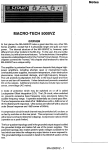
1
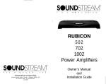
RUBICON
Angina
A4
Power Amplifiers
Owner’s Manual
and
Installation Guide
Conuru fulations!
Table of Contents
You now own a Soundstream RUBICON amplifier, the product of an uncompromising design and engineering philosophy. Your Soundstream RUBICON
amplifier will outperform any other amplifier in the world.
Design Features for the ANGINA ................................................ p 4 - 5
Design Features for the A4 .........................................................
p6- 7
Callouts for the ANGINA .............................................................
p8-9
Soundstream amplifiers are the result of American innovation and craftmanship
with the highest quality control standards. When properly installed, they will
provide you with many years of listening pleasure. Should your amplifier ever
need service or replacement due to theft, please record the following information which will help protect your investment.
Callouts for the A4 .....................................................................
pie-11
Model and Serial #
Hawkins Bass ControlTM Theory and Use ................................... p 13
Dealer’s Name
Wiring ........................................................................................
Pl4
Date of Purchase
Installation and Mounting ............................................................
p 15
Installation Shop
Level Setting and Trident Protection ........................................... p 16
Installation Date
Sample System Diagrams .........................................................
p 17 - 20
Troubleshooting and Service .......................................................
p 21
To maximize the performance of your system, we recommend that you thoroughly acquaint yourself with its capabilites and features. Please retain this
manual and your sales receipt for future reference.
CAUTION!
F
Prolonged listening at high levek may result in hearing loss.
Even though your new Soundstream R&icon amplifier
sounds better than anything you’ve ever heard, exercise
caution to prevent hearing damage.
2
Crossover Adjustments for the ANGINA.. .................................... P12
Crossover Adjustments for the A4 .............................................. p 12
Specifications for the ANGINA ...................................... <. ........... p 22
Specifications for the A4.. ...........................................................
1
3
p 23
Desiun features of the An&a
SLA/SHTM (Speaker Load Adapting I Subwoofer Hyper-Efficient) This
new dual function technology currently operates in two different ways in
different models. In subwoofer applications the power supply tracks the
incoming audio signal and increases or decreases its own voltage level
to mirror the input. This design results in enormous low impedance, low
frequency stability and maximum efficiency, since no power is wasted
maintaining an unnecessarily high voltage level in the power supply.
TridentTM Protection Topology provides three types of protection:
1. Output protection against short circuits or improper loads.
2. Ground fault detection: Shuts down the amplifier when a significant
voltage (>5 Volts) fluctuation occurs between electrical (turn-on lead)
and battery ground.
3. Thermal Protection: Puts the amplifier into shutdown in extreme
thermal conditions.
Hawkins Bass ControlTM provides a focused subwoofer boost (O-6dB
at 45Hz) and routes otherwise wasted amplifier power back to the audible bandwidth.
Harmonic Bass AlignmentTM The 2nd and 3rd order harmonic peaks
are critically aligned to fundamental peaks at low frequencies. This produces tighter, more accurate bass reproduction.
Drive Delay llTM Amplifier section powers up 2 to 3 seconds after the
power supply eliminating turn-on pops. Turn off process is reversed:
Amplifier section turns off first, followed by the power supply.
ChassisinkTM All transistors are ideally located and sandwiched between the circuit board and the heatsink to provide cool efficient amplifier operation.
Differentially Balanced RCA Input eliminates ground loop related
noise in the audio path.
Variable Crossover Network 12dB/octave low pass filter that is selectable at 60, 80 or 1 OOHz.
Symmetrical Discrete Balanced Class A Drive Board auto-adjusts
for linear performance while driving low impedance loads.
4
Desim Features of the An&a
High Level Input with terminal block connector will accept a speaker
level input. This allows the user to hook this amplifier up to any factory
headunit.
Auto Turn On allows the amplifier to turn on without the use of a remote turn on wire, when the amplifier is using the high level inputs.
Remote Wire Output provides a +12 volt output to turn on another
amplifier.
Line Level Output will allow the use of another Soundstream amplifier
to run the front speakers, while still retaining the factory head unit. This
option is only available when the high level inputs are used.
Desiun Features of the A4
+
+
RUBITM Power Supply (Rapid-Use Branched Impulse) Our new power
supply eliminates “power sags” during low frequency reproduction by
rapidly increasing the duty cycle, stabilizing the power supply and allowing it to deliver the power required when reproducing low frequencies.
Also, greater reserve gate power is now stored for low voltage conditions
that occur during extreme conditions.
STACTTM (Stabilized Apex Current lopology) Reduces power supply
stress by 50%. Use of inverted channels usually degrades the stereo
image due to phase reversal of even order harmonic distortion that occurs between the inverted channels. In the STACT design inversion is
done at the power amplifier drive stage. Since the fully symmetrical power
amplifier produces no even harmonic distortion itself and all preamp circuitry (which does produce even harmonics) is run completely in phase,
no even harmonic distortion phase reversal occurs.
+
TridentTM Protection Three types of protection for RUBICON amplifiers:
1. Output protection against short circuits or improper loads.
2. Ground fault detection shuts down the amplifier when a significant (5
volt or greater) voltage fluctuation occurs between audio ground and battery ground.
3. Thermal protection will shut the amplifier down in extreme thermal
conditions.
+
Hawkins Bass Control Provides focused subwoofer boost and routes
wasted subsonic power to the audible bandwidth. The A4 contains the
fixed Hawkins Bass Control which allows you to boost bass 6dB at
45Hz. A built-in subsonic filter at 45Hz helps protect the speakers.
Desiun Features of the A4
+
ChassisinkTM All transistors are sandwiched between the circuit board
and the heatsink to provide cool efficient amplifier operation in a smaller
package.
+
Continuously Variable Lowpass Crossover Networks 12dB/oct low
pass crossover variable from 50 to 220Hz.
+
Built-in Staggered S.I.P. Crossover Networks Built-in high pass electronic crossover is designed to send high pass information to the amplifier with a 12dB/oct slope.
+
Flexible Input Level Control 200mV to 5V input sensitivity. Stereo
level control allows user to optimize system level control.
+
Symmetrical Discrete Balanced Class A Drive Boards Auto-adjusts
for linear performance in low impedance loads.
+ Harmonic Bass AlignmentTM The 2nd and 3rd order harmonic peaks
are critically aligned to fundamental peaks at low frequencies. This produces tighter, more accurate bass reproduction.
+
Drive Delay II Muting TM Amplifier section now powers up 2 - 3 seconds
after power supply, eliminating turn on pops. Turn off process is reversed.
Amplifier section turns off first, followed by power supply.
+
Dynamically Optimized Power Grid TM Power grid is now evenly distributed between primary and secondary power supplies, providing greater
dynamics and improved RF filtering.
6
7
Cal/outs for the An&a Tbp Panel
Callouts for the An&a Front Panel
LP
X-OVER
SOUNDSTREW
/
1
1.
Power LED - Indicates amplifier power.
5.
+12V - Connected to a fuse or circuit breaker, then to the battery’s
positive terminal.
2.
Subsonic / Hawkins Bass Control Switch - Select “Subsonic” to
engage the Subsonic filter at 13Hz. Select ‘Hawkins E&s Confrol”to
engage the +6dB boost @I 45Hz for the lowpass channel.
6.
Remote In - Remote turn-on input from the head unit. Accepts +12V.
3.
4.
7.
Input Selection Switch - Select “SPKR IN / RCA OUT” to engage the
high level speaker inputs and the RCA’s become outputs to run to another amplifier. Select “RCA IN” to engage the RCA’s as inputs.
Speaker Connection Terminal - Speaker connections to the mono
sub channel.
8.
High Level Speaker Inputs - Left and right inputs from a speaker level
source.
Low Pass XOVER Switch - A selectable crossover frequency switch
at 60, 80 or 1 OOHz.
9.
Inputs - Right and left RCA inputs for the mono sub channel.
10.
Input Level -The mono channel input level control.
11.
Fuse - Main power supply fuse. Warning: Replace only with the same
value fuse!
12.
GND - Main ground connection. Bolt to a clean chassis point in the
vehicle.
13.
Remote Out - Remote turn-on output to control a second amplifier.
8
9
Callouis for the A4
Cal/outs for the A4
Top Panel View
‘
8.
Remote - Remote turn-on input from the head unit. Accepts +12V.
9.
GND - Main ground connection. Bolt to a clean chassis point in the
vehicle.
10. Speaker Connection Terminal - Speaker connections for channels
l&2 and 3&4.
2.
Subsonic / Hawkins Bass Control Switch - Select “Subsonic” to
engage the Subsonic filter at 13Hz. Select ‘Hawkins Bass Contro/“to
engage the +6dB boost @ 45Hz for the lowpass channel.
3.
ST/MO(S)/LP Switch - Select “ST” for normal stereo operation. “MO”
for bridged mono operation with a single input signal (number 2 input
only). “LP” for low pass bridged mono operation with input from channels 3&4.
ST/M0(3)/LP Switch - Select “ST” for normal stereo operation. “MO”
for bridged mono operation with a single input signal (number 3 input
only). “LP”for low pass bridged mono operation with input from channels 3&4.
4.
5.
11.
Low Pass Filter Control Adjustment - Crossover frequency control
for the internal low pass filter.
12.
Input Levels - Stereo input level control for channels l&2.
13.
Input Levels - Stereo input level control for channels 3&4.
14.
RCA Inputs - Right and Left channel RCA inputs for channels l&2 and
3&4.
15.
Crossover S.I.P.‘s - High pass crossover frequency settings for amplifier.
Input Selection Switch - Selectable inputs for channels 3&4 from
internal (channels l&2) or external (channels 3&4).
Bottom Plate View
0
c- ------------
Front Control Panel View
6.
Fuse - Main power supply fuse. Warning: Rep/ace on/y with the same
value fuse!
7.
+12V - Connected to a fuse or circuit breaker, then to the battery’s
positive terminal.
10
11
Crossover Adiustmen ts
Hawkins Bass Control
ANGINA CROSSOVER
The ANGINA is designed as a mono subwoofer amplifier. This means the
amplifier will direct 200 watts of pure hard-core bass to your subwoofers. It
handles these low frequencies with a Butterworth, 12dB/octave low pass
filter.
These low pass frequencies are directed by the three position switch which
sits on top of the amplifier as shown in the shaded area below. The switch
selects from the following three frequencies; 60, 80 or 1 OOHz.
Top View of the ANGINA
t
j
Subwoofer drivers in general
have excellent power handling characteristics over
their operational bandwidth. dB
This bandwidth is determined by many factors, including driver design, and
enclosure type. It is possible
to overdrive any subwoofer
Frequency (Hz)
50
Figure 1
driver by sending powerful
signals outside of its operational bandwidth. These potentially damaging signals can be removed by adding a subsonic filter. Figure 1 shows the effectiveness of the Hawkins Bass Control on woofer excursion in a vented enclosure. The woofer travels 7.5mm at 10Hz. With Hawkins Bass Control properly adjusted, this excursion can be reduced to less than 1 mm. This is oi
great benefit to lowering woofer distortion and increasing output.
With Soundstream’s Hawkins Bass Control, the boost and frequency control can provide the “tailoring” needed for any type of “assisted” design and
any woofer in any type of installation.
A4 CROSSOVER
The A4 uses a S.I.P. (Series !n-line Package resistor network) for high pass
crossover functions (factory set at 150Hz). However, the low pass is adjusted
using a 12dB/oct variable crossover that has a range of 50 to 220Hz as seen
in the shaded area below.
The Angina and A4 amplifiers share the same fixed Hawkins Bass Control
technology. A two position switch on the top of the amplifiers control the
‘Hawkins Bass Control’or ‘Sub Sonic’ filters as seen in the shaded area
below. When the ‘Hawkins Bass Control is engaged a 6dB boost is applied
at 45Hz. The ‘Sub Sonic’setting will engage the 13Hz subsonic filter with nc
boost.
Front View of the A4
Top View of the ANGINA
/’
IMPORTANT NOTE:
7
On the A4 amplifier, a full range signal can he achieved by removing
the SIX entirely.
\
/
12
Top View of the A4
Ins tda tion and Moun ting
Wiring
A MPLINER LOCATION
POWER A ND GROUND
The
RUBICON amplifier employs highly efficient circuitry, a custom-engineered
heat sink, and a unique Chassisink construction to maintain lower operating temperatures. Additional cooling may be required if the amplifier is located in a tightly
confined area or when driving especially low impedance loads at extremely high
levels.
To ensure maximum output from your RUBICON amplifier, use high quality, lowoss power and ground cables and connections. The RUBICON amplifiers will
Iccept an 8 gauge power and ground cables. Determine from the chart below the
ninimum and maximum gauge power and ground wire for your application.
I
I
up
to 70’
I
up
to 20’
Angina
8 or 10 gauge
8 gauge only
A4
8 or 10 gauge
8 gauge only
When mounting the amplifier, it should be securely mounted to either a panel in the
vehicle or an amp board or rack that is securely mounted to the vehicle. The
mounting location should be either in the passenger compartment or in the trunk of
the vehicle, away from moisture, stray or moving objects, and major electrical components. To provide adequate ventilation, mount the amplifier so that there are at
least two inches of freely circulating air above and to the sides of it.
I
CIRCUIT BREAKERS AND FUSES
:XTERNAL
.ike all audio components, the RUBICON amplifier must be fused near the battery.
4 fuse or circuit breaker must be located within 18” of the batterv. This will orevent
I fire in the event of a sholted cable. See the chart below to determine the correct
use value.
MOUNTING THE AMPLIFIER
;:
C.
NTERNAL
-he RUBICON Angina and A4 amplifiers are fused with automotive-type fuses.
n the event of blown power supply fuses, replace with the correct value fuse found
I the chart below. Never replace the fuse with a higher value than what is
supplied. This may result in amplifier damage and will void the warranty!
a.
RUB/CON Amplifier Fuse Values
C.
Amplifier Fuse
Battery Fuse /Circuit Breaker
Angina
25 amp automotive
30 amp
A4
25 amp automotive
30 amp
Using the amplifier as a template, mark the holes on the mounting surface.
Remove the amplifier and drill the holes for the mounting screws.
Secure the amplifier to the mounting surface using the supplied hardware.
W/RING
b.
d.
re.
Run and connect the audio signal and remote turn-on cables to the amplifier from the source unit.
Carefully run the positive cable from the amplifier to a fuse or circuit breaker
within 18” of the battery.
Connect the fuse or circuit breaker lead to the battery. Leave the circuit
breaker off or the fuse out until everything is bolted down.
Secure the ground cable to a solid chassis ground on the vehicle. It may be
necessary to sand paint down to raw metal for a good connection.
Double check each and every connection!
Reconnect the fuse or circuit breaker.
REMOTE TURN-ON
Connect the “Remote” line to the turn-on lead from the source unit. When +12
,olts is received, the amplifier will turn on. Note: Remote wire is not needed
vhen the Angina is using the speaker level inputs.
SIGNAL CABLE
Jse a high quality cable that will be easy to install and has minimal signal loss to
guarantee optimum performance.
SPEAKER CABLE
-he RUBICON amplifiers will accept up to 8 gauge speaker cable. Use a high
quality, flexible, multi-strand cable for best performance and longevity.
14
POWER UP
.
Power up the system and look at the Power LED; there may be a 2-3 second delay
from the time the source unit is turned on to the time that the LED on the amp turns
on, which is normal. Once the amplifier LED is on and the source unit is playing,
you should have sound coming from the speakers.
f
IMPORTANT ANGINA NOTE:
e initial power up connection will leave the amplifier power light on for abo
one minute after turning off. Normal operation will occur after that.
15
Level Setting
~
The input levels are adjusted by means of the input level controls located on the
front of the amplifier as shown below in the shaded area. This is a unique dualstage circuit that adjusts both level and gain. This topology maintains better S/N
Ratio even when using sources with minimal output.
In the ideal situation, all components in the audio system reach maximum undistorted
output at the same time. If you send a distorted signal to an amplifier, it is simply
going to amplify distorted information. The same holds true if an outboard pro-
cessor or crossover begins to distort before you have maximum output from the
amplifier. By setting all components to reach clipping at the same time, you can
maximize the output of your system. For the RUBICON amplifier, follow these
steps for setting the input levels:
1.
2.
3.
Turn the amplifier’s input levels to minimum position (counterclockwise)
Set the source unit volume to approximately 3/4 of full volume.
While playing dynamic source material, slowly increase the amplifiers’ input
level until a near maximum undistorted level is heard in the system.
Triden f Pro tee tion Circuiitrv
Your RUBICONA4, ANGINA amplifiers are protected against both overheating and short circuits by means of main power fuses and the following
circuits:
+
Speaker Protection
Ground fault Protection
+
+
A fail-safe thermal protection circuit
16
An&a Samde Svstems
[R e m o t e Ampbfier RA
Turn On
DIo
\
/
(after market radio)
Troubleshoo thy
An&a and A4 Sarnde System
Complete Sys feti while using a Factory Radio
CAUSE
PROBLEM
Spmkrr Lwcl O”,
RADIO
No Sound and power LED is not
lit
1. No power or ground at the
amp
2. No remote turn-on signal
3. Blown fuse near the battery
1. No signal input
2. Speaker leads may be
No sound, power LED is lit
shot-ted
3. Speaker leads may be
referenced to ground
Amplifier output cuts on/off
repeatedly
1. Speaker output may be
shorted to ground.
2. Speaker leads may be
shorted to each other. Check
continuity with a volt meter.
Repeatedly blow amp fuse;
frequent activation of Trident
protection or Smart Power
Supply Circuit
1. Speaker or leads may be
shot-ted
2. Amplifier load may be too low
3. Verify adequate amp
ventilation
/ NOT’: If you experience blown main power supply fuses, ii is )
likely fhat the amplifier is seeing a dead short, either in the
speaker wire or in the speaker itself. Rectify the problem before
blowing multiple fuses! DO NOT increase values beyond the
original fuse vafue! Doing so will void your warranty and may
damage your amplifier.
Front Speakers
Service
Your Soundstream RUBICON amplifier is protected by a limited warranty.
Please read and send in the enclosed warranty card.
21
Specifications for the A4
SDecifica tions for the An&a
MODEL
Angina I
2 fi Mono
(14.4 Vdc)
4 Sz Mono
(12.6 Vdc)
100wx1
THD
Signal to Noise
Frequency Response
Stereo Separation
Damping
Input Sensitivity
Input Impedance
I
2oowx1
MODEL
I
I
I
2 Q Stereo
4 Q Bridged
(14.4 Vdc)
25Wx4
5owx4
1oow x2
THD
Signal to Noise
Frequency Response
Stereo Separation
Damping
Input Sensitivity
Input Impedance
<O.l%
>90dB
20Hz (+0.5dB) to 100Hz (-3dB)
NA
>lOO
200mV to 5.0 Volts
1 Ok Ohms
<O.l%
>l OOdB
20Hz to 20kHz 2 0.5dB
>90dB
z-200
200mV to 5.0 Volts
1 Ok Ohms
Crossover Specifications
Cross0 ver Specifications
Low Pass:
A4
4 Cl Stereo
(12.6 Vdc)
Low Pass:
High Pass:
Full Range:
Select between 60,80 and 1 OOHz @ 12dB/Octave
Hawkins Bass Control
50Hz - 220Hz, 12dB/Octave
Removable SIP @ 150Hz, 12dB/Octave
Removing the SIP chips all together
Hawkins Bass Control
Hawkins Bass Control “IN” is a +6dB boost at 45Hz
Sub Sonic filter frequency is at 13Hz
Hawkins Bass Control “IN” is a +6dB boost at 45Hz
Sub Sonic filter frequency is at 13Hz
Dimensions (W x D x H)
Dimensions (W x D x H)
ANGINA: 5.3” X 7” X 2.3”
I
22
A4:
10” X 7” X 2.3”
23