1
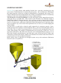
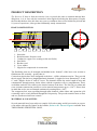
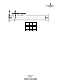
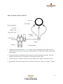
Scirocco II Product Description & User Manual ® …..Scirocco II was a clever choice; we just installed it and forgot it. Now it has passed 7 years of reliable service, however without care or maintenance……… 2 INDEX SYSTEM CONCEPT ............................................................................................................................................ 4 PRODUCT DESCRIPTION ................................................................................................................................ 5 HOSE CONSTRUCTION .................................................................................................................................. 5 MATERIAL & CAPACITIES............................................................................................................................ 5 FLANGE DIMENSIONS (PN10) ...................................................................................................................... 6 STANDARD ACCESSORIES (INCLUDED) ....................................................................................................... 8 ADDITIONAL ACCESSORIES........................................................................................................................ 8 INSTALLATION .................................................................................................................................................. 9 ASSEMBLY INSTRUCTIONS ......................................................................................................................... 9 EXAMPLE – TOP-FEED HOSE INSTALLATION ........................................................................................ 10 EXAMPLES – END-FEED INSTALLATIONS .............................................................................................. 10 AIR CONROL INSTALLATION .................................................................................................................... 11 USER MANUAL ................................................................................................................................................. 12 GENERAL INSTRUCTIONS ......................................................................................................................... 12 MAINTENANCE ............................................................................................................................................. 12 DO IT RIGHT – AVOID THE TRAPS! ........................................................................................................... 13 HANDLING AND TRANSPORTATION......................................................................................................... 13 MANUFACTURER DECLARATION ............................................................................................................. 14 ENCLOSURE; .................................................................................................................................................... 15 MANUFACTURER DECLARATION– AIR CONTROL .......................................................................................... 15 3 SYSTEM CONCEPT Scirocco II is a high capacity bulk handling flexible hose, especially considering the neat cross section. The driving force is actually the gratis gravity – the vertically force affecting all the resting material (in the silo) waiting for transportation. Consequently this system is intended to handle down hill transportations only. Further on fluidization must be continuously working over the entire transportation line to secure reliable function. The silo must be correctly pre-fluidized to provide and supply powder material into the hose, getting the hose to expected work. If the powder in the silo chute is not fluidized enough, it cannot float neither be feed into the hose –there will never be more material delivered from the hose than fed into it! It does not necessary means that the full silo volume must be fluidized. It is, in most cases, sufficient to effectively fluidize the material close to the outlet opening in an adaptive way to the actual feed requirement and, as well, try to avoid bridging and cavity buildup. The hose ID is, as said before, relatively small compared to its enormous capacity. Consequently the hose inlet opening is small compared with e.g. the well sized and square inlet of an air slide. Thus it is easier to get material out of a silo with a wide opening than from a silo with a small opening. The principle of fluidization does not accept any “dead zones”. It is of importance that both in- and outlet of the hose has a well working fluidization support. It is in these parts obstacles normally appear, especially after a stop. Avoid, steel necks, collars, pipe connections and horizontal shelves which are not fluidized! Avoid also bends and reducers at reception point as it can jeopardize the function. Below picture shows a generally well designed system set-up with continuous fluidization from silo cone to reception box. 4 PRODUCT DESCRIPTION The Scirocco II- hose is from an exterior view very much the same a common material handling hose, it is, in fact, only the external air inlet nipples disclosing the discrepancy. Despite the fact that the hose does not show any wear or weakness after several initial test periods and 10 years of experience, it has got the traditionally sturdy construction. HOSE CONSTRUCTION 1 1. 2. 3. 4. 5. 6. 7. 2 2 3 4 5 6 7 Inner tube Reinforcement; Polyester cord Conductive cupper wire (resting on the steel helix) Steel helix Breaker cord Cover rubber Nipples for compressed air connection The fluidizing parts are all arranged and hidden in the “bottom” of the hose cross section as fluidization acts vertically –gravity that is! Connection nipples have been integrated to the hose –visible at bottom exterior. They provide the air supply into the hose longitudinal main channels, 3 nipples for hose dimensions 3, 4 and 6”, and 5 nipples for the 8” and 10” hoses. The channels follow the entire length of hose and communicate through narrow choke inlets with the expansion cells or compartments. These are hidden under the felt visible in the interior bottom of the hose. The PA felt is a robust and wear resistant construction possible to resist material temperatures up to +120oC. Please bear in mind that we do not recommend continuously running above +90oC. The compressed air, now travelling through main channels, choke inlets and expansion cells eventually can be evenly diffused through the felt porosity. The powder material starts to flow and true fluidization has been created! MATERIAL & CAPACITIES Several materials have been subject to empiric full scale testing and all test results are reported in tables with specific figures in the booklet; Scirocco II® Facts & Figures available from TRELLEBORG INDUSTRIAL HOSE. 5 FLANGE DIMENSIONS (PN10) Top feed flange End flange End flange Dim 3” 4” 6” 8” 10” D 200 229 285 343 405 HC 160 180 240 295 350 B 111 130 179 234 284 d 18 18 22 22 22 Top flange nxv 2x45 2x45 2x45 4x30 4x30 ------------------------------------- F 200 220 285 340 395 E 160 180 240 295 350 C 76 115 156 204 250 nxe 8x17 8x17 8x17 8x22 12x22 s 45 45 45 45 30 Standard dimensions -flanges 6 A B Dim 3” 4” 6” 8” 10” A 240 280 380 400 420 B ~80 ~80 ~80 ~80 ~80 7 STANDARD ACCESSORIES (Included) Valve manifold –The Air-control Pneumatic tubing and quick connectors Included std accessories coming with the delivery Plastic tube: 10 x 1, 5 mm Quick coupling: G1/4” – 10 mm Air-control, FESTO: - 1 manual closing valve –G ¼” - 1 electrical on/off valve – normal power 230 V, also available for 110 V AC/ 60Hz and 24 V DC. - 1 pressure regulator with gauge. Thread: G ¼” ADDITIONAL ACCESSORIES Our experience points at highest functional safety when the system is completed with top of the art fluidizing supporting components. We offer a range of reliable professionally designed standard components ; Fluidization elements and cones in various sizes suitable for pre-fluidization. Fluidization containers for material ”drop-stations”. A simplified valve manifold to conduct pre-fluidization additional components Please contact TRELLEBORG INDUSTRIAL HOSE or your local supplier for more information. 8 INSTALLATION ASSEMBLY INSTRUCTIONS Hose inclination: The ultimate inclination angle of this system is between -3 and -10 depending on material properties and generally recommended to be evenly minus 5. Steeper angle do not provide better capacity. It is important to watch the hose verticality during installation so the felt is positioned at vertical bottom to optimize fluidization effect. The unique channel/cell design of Scirocco II gives certain abilities e.g. the hose starts without any requirements of material counter pressure and it can be emptied without any problems at restart. Bending radius: Each size of hose has a bending radius limitation as to below table; 3”: 4”: 6”: 8”: 10”: Minimum bending radius = 600 mm Minimum bending radius = 800 mm Minimum bending radius = 1000 mm Minimum bending radius = 1300 mm Minimum bending radius = 2000 mm A radius more narrow than they mentioned above might impact the capacity and also cause damage to the helix. Points of connection; Each hose is tailor made to customer specification. Consequently the exact length must be a customer issue and first responsibility. It is important that the structure open length between “A and B” fully match the length of the corresponding hose as physical stretch and compression by compulsion might affect the function. Suspension: The installation or support of the hose is an easy issue. Normally the polyester straps between the hose and a steel cable or a cable ladder is enough. The distance between supporting points is recommended to approx. 1 meter to maintain an evenly working downhill transportation. A sudden up-hill part of the line, independent how short it might be, is never OK! Horizontal curves call for a reinforced support to control a correct bending radius within the tolerances stated above. Potential control wire: The conductive cupper wire is a safety part of the construction to protect against static electricity build-up. It always must be physically attached and in galvanic contact with the end couplings to secure a proof connection and protect against sparks to be formed. Coupling shell-halves: When re-assembly the couplings, please note that the shell halves marked 1 and 2 must take the same positions as originally mounted by the manufacturer. 9 EXAMPLE – TOP-FEED HOSE INSTALLATION This is likely the most common attachment of hose to load point “A”, here shown with a prefluidizing cone attached to the silo bottom and on top of the valve. EXAMPLES – END-FEED INSTALLATIONS The pictures below show end-feed attachment examples. This type of attachment calls for appropriate pre-fluidization arrangements to grant continuously working fluidization, watch also the important bottom fluid element actually touching the hose opening! End-feed hoses attached to special feed boxes, here equipped with supporting fluidization elements. 10 AIR CONTROL INSTALLATION 1. Attach the plastic tube to the Scirocco II hose exterior air nipples and to multi-way distributor unit -use the quick connectors and the plastic10x1,5mm tube coming with installation package. 2. Attach the multi way distributor inlet to the air-control manifold out-put side. Keep the distance to hose below 2 m if possible. It will reduce pressure drop. 3. Connect the power cable to socket of electric magnet valve. Please watch power type! 4. Eventually connect the compressed air feed line to input side of the ”air-control” -Thread ¼” 11 USER MANUAL GENERAL INSTRUCTIONS Clean dry air: Clean dry air from a compressor is required to provide the supporting air cushion and get the hose started. We do recommend the standard of compressed air described in ISO8573-1 with sub-classification; 3.2.3 alternatively 3.4.3 depending on lowest possible ambient temperature. Low feed pressure: The ”lifting” ability of Scirocco II starts at extremely low pressures. The gauge pressure consequently should be adjusted accordingly, preferably somewhere between 0,05 and 0,5 Bar. Maximum allowed pressure to the feed channels of the hose is stated to be maximum 2 Bar. Likewise the volume flow here is extremely low –between 20 and 100 l/m.! To obtain quick and optimum air supply calibration it is better to start with the reduction valve closed and gently start open, than opposite around as a too high opening pressure could create “volcano” effect in the material bed. Such effect does not provide the lifting function. Cope with a smaller pressure drop between air-control and hose. Therefore adjust the valve to a gauge value between 0,5 and 1 Bar. Keep the distance between air-control and hose low, if possible <2m, to minimize pressure drop. Continuously fluidization: Fluidizing transport system always requires continuous fluidization over the entire line length. One small “gap” will seriously jeopardize the function. The principle of continuity rules here, consequently the fluidizations starts already in the silo bottom with an accurate pre-fluidization and must not cease before the very end of hose at reception point! A professionally designed line never includes necks or areas not fluidized. True fluidization will never arise from air cannons or shooters; it comes from cunningly designed elements only! Dry materials: The powder materials aimed for this system must be dry. There are, of course, always a smaller humidity content naturally in powders, but such content must be less than 0,2% to grant a well working function. Gypsum is a natural exception as the “water” content here is in crystal phase which do not affect the bad way. MAINTENANCE Scirocco II does not contain any moving parts –thus it does not require any maintenance at all! This is valid for the hose line only. Valves and other components with moving parts have to be checked and maintained accordingly suppliers instructions! 12 DO IT RIGHT – AVOID THE TRAPS! Dead zones, where the material is not fluidized must be avoided. Humid, greasy and dirty air might clog the felt casing less efficiency or malfunction. Maintain good compressed air quality and a pressure at absolute lowest possible level, and never exceed the maximum allowed 2 bars in the feed channels of the hose. ”Cow bellies” are strictly forbidden, roller coast shape of the line will create start-up problems as also smaller sections of up-hill transportation is against the concept of gravity transportation. The felt and the interior materials of the hose are designed to be resistant to continuous temperatures of +90 C as well to handle some short peaks up to +110 C. If the hose is subject to higher temperature than +120 C, the felt surface goes “glossy” and the important porosity disappears which will jeopardize the function. HANDLING AND TRANSPORTATION The hoses are normally delivered in wooden boxes either in straight lengths or curved accordingly bending radii limitations. Always when handling the hose e.g. transport during installation or lifting during installation, please keep in mind: That bending radii below they mentioned above could affect the helix to impact the cross section negatively. That lifting the hose without support cradle also might affect the hose to kink and in worse case damage the helix and as well cut the conductive cupper wire. 13 MANUFACTURER DECLARATION Manufacturer Name Address Ph.# Trelleborg Industri AB, Industrial Hose Division Johan Kocksgatan 10 0410 – 510 00 Herewith declares, that: Machine/component Type Fluidizing hose – Scirocco II® Main function Bulk transportation of powders possible to fluidize Is produced in accordance with the directives dated June 14, 1989 concerning mutual approach of the members legislation regarding machines 98/37/EC. Above mentioned machine/component must not be put in service until it has been established that the machine in which the components are to be installed conforms to the provisions of Directive 98/27/EC. . Trelleborg, December 2008 …………………………..………….. Peter Larsson Manager, Industrial Hose Division 14 Enclosure; Manufacturer Declaration– AIR CONTROL 15 BU Fluid Handling Solutions Trelleborg Industrie SAS - ZI La Combaude - Rue de Chantemerle - 63050 Clermont-Ferrand Cedex 2 - France Tel. +33 (0)473 258 181 - Fax +33 (0)473 258 217 www.trelleborg.com