1
Chapter 6 EM9 series variable…
EM9 User’s manual
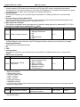
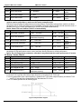
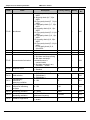
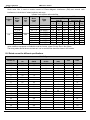
Notice: appropriate adjustment of these two parameters can realize electric network switching. And not
cause produce stop due to inverter protective.
Code
Name
Description
Setting Range Factory setting
0: Disabled
0~1
1
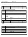
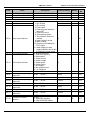
Fb.04 Over-voltage stall protection
1: Enabled
110~140% (DC bus
110~150
120%
voltage) (380V series)
Over-voltage stall protection
Fb.05
point
110~140% (DC bus
110~150
115%
voltage) (220V series)
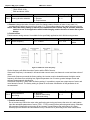
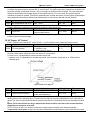
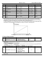
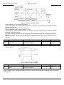
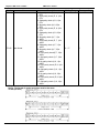
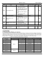
During deceleration, the motor’s decelerating rate may be lower than that of inverter’s output frequency due to the
load inertia. At this time, the motor will feed the energy back to the inverter, resulting in DC bus voltage rise. If no
measures taken, the inverter will trip due to over voltage. During deceleration, the inverter detects DC bus voltage
and compares it with over-voltage stall protection point. If DC bus voltage exceeds Fb.05, the inverter will stop
reducing its output frequency. When DC bus voltage become lower than Fb.05, the deceleration continues, as shown
in following figure.
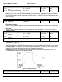
Code
Name
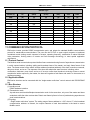
Figure 6-23 Over-voltage stall function.
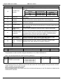
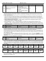
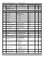
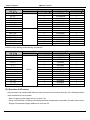
Fb.06
limited mobility selection
Description
0:Limit has been effective
1:Constant speed limit
when the invalid
Setting Range
Factory setting
0~1
1
Automatic limiting feature is always valid under acceleration and deceleration, constant speed automatically
limiting the effectiveness of a choice by the automatic flow limit (Fb.06) decision. Fb.06 = 0 that constant speed,
automatically limiting the effective; Fb.06 = 1, said constant speed, the automatic limit is invalid. Restricted flow
for the automatic, the output frequency may change, so the required constant output frequency when running
more stable situation, should not use the automatic current limiting function. When the automatic current limiting
effective, due to the lower limit level setting, it may affect the inverter overload.
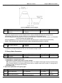
Code
Name
Description
Setting Range
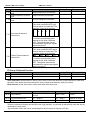
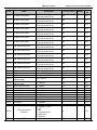
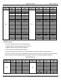
Fb.07
Auto current limiting threshold
100~200%
100~200
Fb.08
Frequency decrease rate
when current limiting
0.00~50.00Hz/s
0.00~50.00
Factory setting
G model: 160%
P model :120%
10.00Hz/s
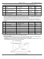
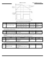
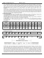
During acceleration, the motor’s accelerating rate may be lower than that of inverter’s output frequency due to the
load inertia. If no measures taken, the inverter will trip due to Acc over current. With auto current limiting function,
during acceleration, the inverter detects output current and compares it with auto current limiting threshold set by
Fb.07. If output current exceeds Fb.07, the inverter will decrease its output frequency according to the decrease
47