1
Mar. 16, 2006
US 2006/0055549 A1
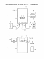
Further, in at least one embodiment, the DC output
accordance With at least one embodiment of the present
(or absence thereof) of the AC adaptor 32 may be used by
invention. In the illustrated example, the communication
device 14 may be con?gured such that the housing 30 is
provided With a battery compartment 38 con?gured to
[0042]
the communication device 14 to monitor the status of poWer
supply for the circuit to Which the AC adaptor 32 is attached.
To illustrate, While DC poWer is received by the AC adaptor
32, the communication device 14 may regard the status of
the poWer supply as available (i.e., poWer is available in the
respective circuit). HoWever, When supply of DC poWer
receive one or more batteries 40 (e.g., a 9V battery). The
communication device 14 may be provided With a commu
nication line 42 connected at a ?rst end 44 to poWer the
communication device 14 and at a second end 46 to an
from the AC adaptor 32 ceases or is absent, the communi
adaptor 48 coupleable to the battery 40. The housing 30 may
cation device 14 may regard the status of the poWer supply
as unavailable (i.e., there is a poWer outage on the circuit).
[0043] The communication device 14 further may include
also be provided With a battery cover 50 connectable to the
positioned Within the battery compartment 38.
one or more netWork interfaces (e.g., communication jacks
[0047] During normal operation When poWer supply is
34, 36) for coupling to a netWork, such as a standard analog,
digital, cable or other phone or communications lines. In the
available at the customer location, the communication
device 14 may receive poWer primarily from the outlet 33
via the AC adaptor 32 (FIG. 2). In the event of a loss of
poWer supply on the circuit being monitored by the com
munication device 14, the communication device 14 may
sWitch to receive poWer from the battery 40 to continue
illustrated embodiment, the communication jack 34 includes
an analog telephone jack (e.g., a RJ-ll jack) used by the
communication device 14 to communicate over a telephone
or other netWork via, e.g., phone cord 37 connected to, for
example, a Wall telephone jack 35. Likewise, the commu
nication jack 36 may be provided for the convenience of the
customer so that a dedicated telephone jack is not required
and additional devices may utiliZe the same phone jack
While the communication device 14 continues to have com
munications access. Fax machines, telephones or modems
are examples of devices that may be coupled to the second
communication jack 36. Although FIG. 2 illustrates one
embodiment Wherein the communication device 14 imple
ments a connection to a telephone network for communica
tions purposes, in other embodiments the communication
device 14 may implement a netWork interface to any of a
variety of netWorks, such as a coaxial cable jack for con
nection to a cable netWork, a Ethernet jack or other data
netWork jack for communication via a dedicated data net
Work, a modem chipset for data communications over a
telephone netWork, a Wireless or satellite transceiver, and the
like.
[0044]
It should be appreciated that While the communi
cation device 14 is illustrated With the ?rst jack 34 and an
optional second jack 36 for adapting to a standard telephone
line, in other embodiments the communication device 14
may communicate With the receiving system (e.g., modem
data server 18 and IVR system 16) via the netWork 20 in a
Wireless, cellular, or other means of communication that
Would not require access to a Wired analog or digital
communication system. As such, the communication device
14 may be provided With Wireless capabilities for commu
nicating With the netWork 20, such as, for example, a 900
MHZ or 2.4 GHZ radio frequency (RF) transceiver com
monly used in Wireless telephones or a RF transceiver
compliant With one or more Wireless data netWork standards
such as IEEE 802.11a/b/g. Further, in the illustrated
example, the communication device 14 is provided With
modem capability for communicating, via a telephone net
Work or cable netWork system capable of DTMF signaling,
housing 30 to cover the battery 40, When the battery is
operation.
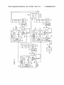
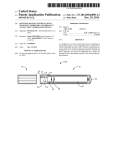
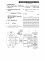
[0048] Referring noW to FIG. 4, an exemplary arrange
ment of outage detection devices to form a particular imple
mentation of the outage noti?cation system 10 is illustrated
in accordance With at least one embodiment of the present
invention. In the illustrated example, the outage noti?cation
system 10 includes a ?rst outage noti?cation device 60 and
a second outage noti?cation device 62, Which are similar to
the outage detection devices 12 illustrated in FIG. 1, and
Which are referred to as partner or “P1” devices herein. The
illustrated outage noti?cation system 10 also includes a
communication device 64 substantially similar to the com
munication device 14 illustrated in FIGS. 1-3. Each of the
?rst and second outage detection devices 60 and communi
cation device 64 may be provided With batteries 40 and AC
adaptors 32, as discussed above.
[0049] The ?rst and second outage detection devices 60,
62 and the communication device 64 may be arranged to
receive electric poWer from respective circuits at the cus
tomer location during normal operation and, in the event of
a loss of poWer supply at the customer location or on a
particular circuit, the devices 60, 62 and 64 may be each
con?gured to sWitch to battery 40 poWer during an inter
ruption.
[0050] As With most customer locations, such as private
residences or business locations, poWer typically is received
from the electric utility through a meter and into a main
breaker box or fuse box 66. Although there are a number of
con?gurations of poWer supply, such as single and three
phase systems utiliZing various amounts of current and
voltage and having a number of fuse boxes, meters or mains,
a single fuse box 66 having a ?rst circuit 68, a second circuit
70 and a third circuit 72 Will be described for purposes of
With the IVR system 16, as Well as negotiating a data
clarity and simplicity herein. A plurality of devices or
appliances 74 may exist on each of the circuits 68, 70 and
72 Which may include outlets 76 into Which the AC adaptors
connection, such as via the Internet or a Wide area netWork
32 may be plugged to receive poWer and monitor the poWer
for communication With the modem data server 18.
supply on the respective circuits 68, 70 and 72.
[0045] The communication device 14, the outage detec
[0051] It Will be appreciated that While the ?rst and second
outage detection devices 60, 62 and communication device
tion device 12, or the detector/controller 13 may include a
detector for detecting
[0046] Referring to FIG. 3, an exemplary back vieW of the
communication device 14 shoWn in FIG. 2 is illustrated in
64 are shoWn coupled in this manner, additional circuits 78
and additional outage detection devices 60, 62 may be
provided in various con?gurations such that all of the