1
2
TTSIM-1 Sensor Interface Module Installation/Operation Instructions
Installing the TTSIM-1
Note: To avoid damage to the TTSIM-1, store the unit in it’s packaging
until ready to install.
Select the mounting position
Choose a location where the module will be protected from the elements,
temperature extremes or vibration. The TTSIM-1 is designed to be
snapped onto standard 35 mm DIN rail. Existing electrical or instrumentation cabinets with spare rail space make good mounting locations. It is
also possible to install a small section of DIN rail directly on a wall or cabinet surface and mount the TTSIM-1 in any location as long as it does not
create a tripping hazard or expose the TTSIM-1 to impact damage. The
TTSIM-1 should be mounted within 1200 m (4000 feet) wire run from the
controlling TTDM or control system host. (Contact the factory for methods
to increase the wire run distance beyond 1200 m).
Important: The TTSIM-1 is an electronic unit. Take the following
precautions to avoid damage to electronic components:
• Handle with care, avoid mechanical shock and impact.
• Keep dry.
RS+
23
24
AC
22
AC
21
AC
20
RS–
17
SHLD
RS+
16
AC
15
AC
14
AC
13
RS–
• Avoid contact with metal filings, grease, pipe dope and other contaminants.
SHLD
• Avoid exposure to static electricity by touching a nearby piece of
grounded equipment or water pipe prior to handling the TTSIM-1.
TYPE NM
LISTED
Leak Location Module
Network
Address
• Remove the TTSIM-1 from it’s packaging and snap onto the DIN rail
with the release tab towards the bottom.
1
2
3
4
5
6
7
• Note: When properly oriented, there will be two terminal strips on the
top of the module and one on the bottom. See Figure 1.
8
9
10
BLK
RATING: 24Vac ±10%
50/60 Hz 3VA
GND
76LJ
SIGNAL SYSTEM UNIT
GRN
YEL
• Secure a sufficient length of DIN rail to the desired mounting surface, or
locate an existing DIN rail with sufficient space to install the TTSIM-1.
US
TTSIM-1
RED
Mounting the TTSIM-1 module (without NEMA 4x Enclosure-Figure 1)
11
12
Release tab
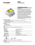
Figure 1. DIN Rail Mount
AC
24
AC
23
AC
22
RS+
SHLD
21
RS–
20
AC
AC
17
AC
RS+
16
TYPE NM
US
TTSIM-1
LISTED
Leak Location Module
RATING: 24Vac ±10%
50/60 Hz 3VA
Network
Address
1
2
3
4
Note: Rough-in and final connections do not have to be completed at the
same time, however make sure to replace the cover and tighten the cover
screws if the enclosure will be left in a partially installed condition
overnight or longer.
Figure 2. NEMA 4x Enclosure
5
6
7
8
9
10
GND
76LJ
SIGNAL SYSTEM UNIT
BLK
• In order to provide maximum electrostatic discharge protection, and to
be CE compliant, the DIN rail must be grounded.
15
GRN
YEL
• Rough-in conduit as required and pull the cables for power and telemetry. Leave approximately 20cm (8") for connections to TTSIM terminals.
Pull in the sensor circuit leader cable.
14
RED
• Secure the TTSIM-ENC to any convenient vertical surface using the four
corner mounting holes and hardware suitable for the selected surface.
13
RS–
• Plan conduit alignment and drill holes as necessary.
• A typical outdoor or harsh environment installation will require up to
three holes in the TTSIM-ENC: one for inbound power and telemetry,
one for outbound power and telemetry and one for the sensor cable
leader. See Figure 2.
SHLD
Mounting the TTSIM-1 module in the optional NEMA-4X Enclosure-Figure 2
11
12
35 mm
DIN rail