1
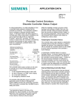
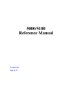
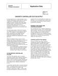
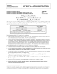
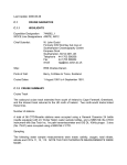
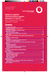
Siemens
Energy & Automation
USER'S MANUAL
UM353TP-1
Rev. 1
April 2002
SIMULATED ANALOG INPUTS
s
ANALOG OUTPUTS
AOUT1
s
AIN
AOUT1
AIN1
AIN
AOUT2
AIN2
AIN
AOUT3
AIN3
AIN
NC
AIN4
2 4 2 3. 4 5
AOUT2
T C2 0 5 3 . P
S
AOUT3
PB1
100
P
L
S
80
ACK
UNIVERSAL ANALOG INPUTS
60
DISCRETE OUTPUTS
DOUT2
DOUT1
D
PB2
40
A
M
20
UNITS
0
AINU1
b
a
d
c
AINU2
b
a
d
c
LOOP
RELAY OUTPUTS
0
ROUT1
NC
NO
ROUT2
NC
NO
LON WORKS
LIL
|
|
CLOSE
||
100
OPEN
Model 353
X03141S2
SIMULATED DISCRETE INPUTS
DIN1
DIN2
DIN3
DIN4
ON
OFF
UNIVERSAL DISCRETE INPUTS
+
+
DINU2
DINU1
CASE GROUND
LONWORKS POWER SIGNAL COMMON
15990-60r2.dsf
Multi-Purpose Training Panel
for
Model 353 Process Automation Controller
UM353TP-1
Contents
Table of Contents
Section and Title
Page
1.0 INTRODUCTION ............................................................................................................................................. 1-1
1.1 PRODUCT DESCRIPTION ...........................................................................................................................1-1
1.2 SPECIFICATIONS.........................................................................................................................................1-2
1.3 PRODUCT SUPPORT ...................................................................................................................................1-3
1.4 EQUIPMENT DELIVERY AND HANDLING .............................................................................................1-4
1.4.1 Receipt of Shipment ...............................................................................................................................1-4
1.4.2 Storage ...................................................................................................................................................1-4
1.5 RELATED PUBLICATIONS.........................................................................................................................1-4
2.0 INSTALLATION............................................................................................................................................... 2-1
2.1 INSTALLATION CONSIDERATIONS ........................................................................................................2-2
2.2 CIRCUIT BOARD HANDLING GUIDELINES ...........................................................................................2-2
2.3 ENVIRONMENT ...........................................................................................................................................2-2
2.4 ELECTRICAL POWER INPUT ....................................................................................................................2-3
2.5 CONTROLLER INSTALLATION ................................................................................................................2-4
3.0 OPERATION ..................................................................................................................................................... 3-1
3.1 ANALOG INPUTS.........................................................................................................................................3-1
3.2 ANALOG OUTPUTS.....................................................................................................................................3-2
3.3 DIGITAL (DISCRETE) INPUTS...................................................................................................................3-4
3.4 DIGITAL (DISCRETE) OUTPUTS...............................................................................................................3-4
3.5 RELAY OUTPUTS ........................................................................................................................................3-4
3.6 ANALOG INPUT UNIVERSAL ...................................................................................................................3-4
3.7 DIGITAL (DISCRETE) INPUT UNIVERSAL .............................................................................................3-4
3.8 MODBUS COMMUNICATION....................................................................................................................3-4
3.9 LIL COMMUNICATION...............................................................................................................................3-5
3.10 ETHERNET COMMUNICATION ..............................................................................................................3-5
3.11 LONWORKS COMMUNICATION ............................................................................................................3-5
3.12 INSTRUMENT GROUNDING....................................................................................................................3-5
4.0 MAINTENANCE............................................................................................................................................... 4-1
4.1 PREVENTIVE MAINTENANCE..................................................................................................................4-1
4.2 TROUBLESHOOTING..................................................................................................................................4-1
4.2.1 Training Panel ........................................................................................................................................4-1
4.2.2 Controller ...............................................................................................................................................4-1
4.2.3 Configuration .........................................................................................................................................4-2
5.0 CIRCUIT DESCRIPTION ............................................................................................................................... 5-1
5.1 GROUNDING ................................................................................................................................................5-1
5.2 ANALOG INPUTS.........................................................................................................................................5-1
5.3 ANALOG OUTPUTS.....................................................................................................................................5-1
5.4 DIGITAL (DISCRETE) INPUTS...................................................................................................................5-2
5.5 DIGITAL (DISCRETE) OUTPUTS...............................................................................................................5-2
5.6 RELAY OUTPUTS ........................................................................................................................................5-2
5.7 UNIVERSAL ANALOG INPUTS .................................................................................................................5-2
5.8 UNIVERSAL DIGITAL (DISCRETE) INPUTS ...........................................................................................5-2
5.9 COMMUNICATION OPTIONS....................................................................................................................5-2
5.10 LONWORKS COMMUNICATION ............................................................................................................5-3
6.0 MODEL DESIGNATION................................................................................................................................. 6-1
April 2002
i
Contents
UM353TP-1
Conventions, Symbols, and General Information
Conventions and Symbols
The following symbols may be used in this manual and may appear on the equipment. The reader should become
familiar with the symbols and their meaning. Symbols are provided to quickly alert the reader to safety related text.
Symbol
DANGER
Meaning
Indicates an immediate hazardous situation which, if not avoided, will result in death
or serious injury.
WARNING
Indicates a potentially hazardous situation which, if not avoided, could result in death
or serious injury.
CAUTION
Indicates a potentially hazardous situation which, if not avoided, may result in minor
or moderate injury.
CAUTION
NOTICE
Important
Note
Indicates a potentially hazardous situation which, if not avoided, may result in
property damage.
Indicates a potential situation which, if not avoided, may result in an undesirable result
or state.
Identifies an action that should be taken to avoid an undesirable result or state.
Identifies additional information that should be read.
Electrical shock hazard. The included Warning text states that the danger of
electrical shock is present.
Electrical shock hazard. Indicated that the danger of electrical shock is present.
Explosion hazard. Indicates that the danger of an explosion hazard exists.
Electrostatic discharge. The presence of this symbol indicates that electrostatic
discharge can damage the electronic assembly.
Qualified Persons
The described equipment should be installed, configured, operated, and serviced only by qualified persons
thoroughly familiar with this User’s Manual. A copy of this manual accompanies the equipment. The current version
of the manual, in Portable Document Format (PDF), can be downloaded from www.sea.siemens.com/ia/.
For the purpose of this manual and product labels, a qualified person is one who is familiar with the installation,
assembly, commissioning, and operation of the product, and who has the appropriate qualifications for their
activities such as:
•
ii
Training, instruction, or authorization to operate and maintain devices/systems according to the safety standards
for electrical circuits, high pressures, and corrosive, as well as, critical media.
April 2002
UM353TP-1
Contents
•
For devices with explosion protection: training, instruction or authorization to work on electrical circuits for
systems that could cause explosions.
•
Training or instruction according to the safety standards in the care and use of suitable safety equipment.
Scope
This manual does not purport to cover all details or variations in equipment, nor to provide for every possible
contingency to be met in connection with installation, operation, or maintenance. Should further information be
desired or should particular problems arise which are not covered sufficiently for the purchaser’s purposes, the
matter should be referred to one of the support groups listed in the Product Support section of this manual.
The contents of this manual shall not become part of or modify any prior or existing agreement, commitment or
relationship. The sales contract contains the entire obligation of Siemens. The warranty contained in the contract
between the parties is the sole warranty o Siemens. Any statements continued herein do not create new warranties or
modify the existing warranty.
General Warnings and Cautions
WARNING
The perfect and safe operation of the equipment is conditional upon proper transport, proper storage, installation and
assembly, as well as, on careful operation and commissioning.
The equipment may be used only for the purposes specified in this User’s Manual.
CAUTION
Electrostatic discharge can damage or cause the failure of semiconductor devices such as integrated
circuits and transistors. The symbol at right appears on a circuit board or other electronic assembly to
indicate that special handling precautions are needed.
•
A properly grounded conductive wrist strap must be worn whenever an electronics module or circuit board is
handled or touched. A service kit with a wrist strap and static dissipative mat is available from Siemens
(PN15545-110). Equivalent kits are available from both mail order and local electronic supply companies.
•
Electronic assemblies must be stored in static protective bags when not installed in equipment.
!
i|config is a trademark of Siemens Energy & Automation, Inc. Other trademarks are the property of their respective owners.
Siemens Energy & Automation, Inc. assumes no liability for errors or omissions in this document or for the application and use of the
information included in this document. The information herein is subject to change without notice.
Procedures in this document have been reviewed for compliance with applicable approval agency requirements and are considered sound
practice. Neither Siemens Energy & Automation, Inc. nor these agencies are responsible for repairs made by the user.
April 2002
iii
Contents
iv
UM353TP-1
April 2002
UM353TP-1
Introduction
1.0 INTRODUCTION
This User’s Manual is for Model 353 Multi-Purpose Training Panels P/Ns 15990-53 and 15990-91. It is organized in
the following sections:
•
Section 1, Introduction - Contains a description of the Training Panel, product support details, and a list of
related publications.
•
Section 2, Installation - Provides Training Panel and controller installation procedures and circuit board
handling guidelines.
•
Section 3, Operation - Identifies and explains the controls and signal displays.
•
Section 4, Maintenance - Furnishes preventive maintenance guidelines and troubleshooting procedures. A Parts
List is at the end of this section.
•
Section 5, Circuit Description - Describes the Training Panel’s circuitry.
•
Section 6, Model Designation - Provides model designation.
•
Section W, Warranty - Consists the warranty statement.
IMPORTANT
Save this User’s Manual and make it available for installing, operating, and servicing the
Training Panel.
1.1 PRODUCT DESCRIPTION
The Multi-Purpose Training Panel provides an effective, low-cost method to introduce the principles of operation
and configuration of the Model 353 Process Automation Controller to engineering, operations, and maintenance
personnel. Actual process operating conditions can be simulated providing a "hands-on" experience without
affecting an on-line process. No connection to a real-world process is required to use the full range of control
features available with a Model 353.
The PN15990-53 Training Panel allows use of all Model 353 features but does not provide for an Ethernet
connection. The PN 15990-91 Training Panel retains all of features provided in the PN 15990-53 Training Panel and
adds an Ethernet cable and connector (for Ethernet communication, the installed controller must include the Ethernet
option board).
The Training Panel consists of a standard controller case with a specially designed front panel. Controls, connectors,
and displays on the front panel are used to select and adjust inputs to and outputs from the controller. Model 353
assemblies are either ordered separately or supplied from the user’s spare parts stock. Typically, assemblies are
installed in the case by the user. An MPU Controller board and Display Assembly are required. An I/O Expander
board, Real Time Clock/Configuration Backup board, and communication option boards can be added as needed,
depending upon the requirements of the process simulation. Refer to the Model 353 User’s Manual, UM353-1, for
board options and installation procedures.
The Panel is completely pre-wired and self-contained. Any Model 353 controller can be easily installed in the
Training Panel by inserting the circuit board assemblies and attaching the Display Assembly. Typically, 120 Vac
power is provided via a standard 3-prong, grounded plug. A 24 Vdc Model 353 can be used; Section 2.4 Electrical
Power Input, in this manual, and UM353-1 describe the case rear terminal connections needed for operating from a
24 Vdc power source.
April 2002
1-1
Introduction
UM353TP-1
SIMULATED ANALOG INPUTS
AIN
AOUT1
AIN1
AIN
AOUT2
AIN2
AIN
AOUT3
AIN3
AIN
NC
AIN4
s
ANALOG OUTPUTS
AOUT1
s
2 4 2 3. 4 5
AOUT2
T C2 0 5 3 . P
S
AOUT3
PB1
100
P
L
S
80
ACK
UNIVERSAL ANALOG INPUTS
60
DISCRETE OUTPUTS
DOUT2
DOUT1
D
PB2
40
A
M
20
UNITS
0
AINU1
b
a
d
c
AINU2
b
a
d
c
LO OP
RELAY OUTPUTS
0
ROUT1
NC
NO
ROUT2
NC
NO
LON WORKS
LIL
|
|
||
100
CLOSE
OPEN
Model 353
SIMULATED DISCRETE INPUTS
DIN1
X03141S2
LONWORKS POWER SIGNAL COMMON
DIN2
DIN3
DIN4
ON
OFF
UNIVERSAL DISCRETE INPUTS
+
+
DINU2
DINU1
CASE GROUND
Modbus Communication Port
Ethernet Communication Port on Rear of Case
15990-60r2.dsf
The Training Panel includes:
•
LED indicators to display the output states of up to four discrete output function blocks (2 relay, 2 digital)
•
Toggle switches to set up to four simulated discrete inputs
•
Plug-in jacks for three analog output function blocks and a switchable voltmeter to monitor the output voltage
•
Four precision potentiometers to set simulated analog inputs
•
Analog input selector switches to connect analog outputs to analog inputs for use in process simulations or
tuning experiments
•
Plug-in jacks to connect the Model 353 to the Local Instrument Link (LIL)
•
Plug-in jacks to connect the Model 353 to LonWorks
•
Ethernet connector (later model Training Panels only)
The switches, potentiometers, and displays permit the simulation of a process and field devices without interacting
with a live process. Engineering, operating, and servicing personnel can become skilled in the use and configuration
of a Model 353 without the threat of a costly process upset.
Possible uses of the Multi-Purpose Training Panel with a Model 353 include: operator training, configuration
development, and controller checkout and calibration.
1.2 SPECIFICATIONS
AC or DC Power Input Requirements .........................Determined by the installed MPU Controller board; refer to
UM353-1 for details; see Section 2 Installation
Controller Performance ...............................................Refer to UM353-1 for details
Environment ................................................................Intended for use in a control room, training room, or office
environment; non-hazardous locations only. See UM353-1 for
temperature, humidity, and other environmental specifications.
Agency approvals listed on the controller nameplate do not
apply in this application.
1-2
April 2002
UM353TP-1
Introduction
1.3 PRODUCT SUPPORT
Product support can be obtained from a customer service center (i.e. Technical Support Group in North America or a
Technical Information Center (TIC) in Asia or Europe). Each region has a customer service center that provides
direct telephone support on technical issues related to the functionality, application, and integration of all products
supplied by the Process Industries Division of Siemens Energy & Automation. Regional contact information is
provided below. Your regional Technical Support Group or TIC is the first place to call when seeking product
support information. When calling, it is helpful to have the following information ready:
•
Product part number or model number and version
•
If there is a problem with product operation:
- Whether or not the problem is intermittent
- The steps performed before the problem occurred
- Any status message, error messages, or LED indications displayed
- Installation environment
Customers that have a service agreement are granted access to the secure area of the Siemens Internet site. This area
contains a variety of product support information. When logging on, you will be prompted to enter your username
and password. All customers have access to the public portion of the site.
NORTH AMERICA
ASIA
TABLE 1-1 TIC CONTACT INFORMATION
Telephone
+1 215 646 7400, extension 4993
Fax
+1 215 283 6358
E-mail
[email protected]
Hours of Operation
8 a.m. to 6 p.m. eastern time
Monday – Friday (except holidays)
Public Internet Site
www.sea.siemens.com/ia/
Repair Service
+1 215 646 7400 extension 4993
Telephone
Fax
E-mail
Hours of Operation
Public Internet Site
Repair Service
EUROPE
Telephone
Fax
E-mail
Hours of Operation
Public Internet Site
Repair Service
April 2002
+011 65 299 6051
+011 65 299 6053
[email protected]
9 a.m. to 6 p.m. Singapore time
Monday – Friday (except holidays)
www.sea.siemens.com/ia/
+011 65 299 6051
+44 (0) 1935 470172
+44 (0) 1935 470137
[email protected]
8:30 a.m. to 4:30 p.m. GMT/BST
Monday – Friday (except holidays)
www.sea.siemens.com/ia/
+44 (0) 1935 470172
1-3
Introduction
UM353TP-1
1.4 EQUIPMENT DELIVERY AND HANDLING
Prior to shipment, each Training Panel is fully tested and inspected to ensure proper operation. It is then packaged
for shipment.
1.4.1 Receipt of Shipment
Inspect each carton at the time of delivery for possible external damage. Any visible damage should be immediately
recorded on the carrier’s copy of the delivery slip.
Carefully unpack each carton and check the contents against the enclosed packing list. Inspect each item for any
hidden damage that may or may not have been accompanied by exterior carton damage.
If it is found that some items have been damaged or are missing, notify the Process Instrumentation Division of
Siemens Energy and Automation immediately and provide full details. In addition, damages must be reported to the
carrier with a request for their on-site inspection of the damaged item and its shipping carton.
1.4.2 Storage
If a Training Panel with an installed controller is to be stored for a period or moved to another location or site,
review the environmental specifications in the Model Designation and Specifications section of UM353-1.
1.5 RELATED PUBLICATIONS
Refer to the following publications for information on the Model 353, including configuration and calibration
instructions, function block (FB) information, circuit board descriptions, troubleshooting procedures, and
instructions for operating the display assembly.
•
User's Manual, Model 353 Process Automation Controller, UM353-1, Rev. 9 or later
•
Local Instrument Link Installation And Service Instruction, SD15492
Current revisions of technical literature can be obtained by visiting the Siemens Energy & Automation, Process
Industries Division Web site at www.sea.siemens.com/ia/. These publications are in Portable Document Format
(PDF) and are available for downloading.
!
1-4
April 2002
UM353TP-1
Installation
2.0 INSTALLATION
This section describes installation of the Multi-Purpose Training Panel and Model 353 controller assemblies. Figure
2-1 shows Training Panels with case option 2 and those with case option 4. These case options have different case
rear connectors and case option 4 includes an Ethernet connector. Refer to the Model 353 User’s Manual UM353-1
Rev 9 or later for additional information about case options.
WARNING
Electrical shock hazard
Hazardous voltage can cause death or serious injury.
Remove power from all wires and terminals before making
connections to the front panel or to the rear terminals.
TOP VIEW
MG00410a
DIMENS.ds4
TOP VIEW
Nameplate
2.67
(67.8)
10.00
(254.0)
2.67
(67.8)
10.00
(254.0)
Dimensions in inches
(millimeters)
Dimensions in inches
(millimeters)
SIDE VIEW
9.38
(238.2)
SIDE VIEW
5.42
(137.7)
11.99
(304.5)
PN 15990-53 Training Panel with
Controller Case Option 2 and
Black Side Entry Connectors;
No Ethernet Connector
9.38
(238.2)
5.42
(137.7)
12.26
(311.4)
PN 15990-91 Training Panel with
Controller Case Option 4 and
Gray or Green Direct Entry Connectors;
With Ethernet Connector
FIGURE 2-1 Multi-Purpose Training Panel Dimensions
April 2002
2-1
Installation
UM353TP-1
2.1 INSTALLATION CONSIDERATIONS
The Training Panel is shipped fully assembled and wired. An overview of the installation follows.
1.
Place the Training Panel on a desktop or other level surface convenient to a source of electrical power. Refer to
Sections 1.2 Specifications and 2.3 Environment.
Note
To move or carry a Training Panel, either firmly grasp the metal front panel or cup your
hand beneath the underside of the controller case and grasp the case where case and front
panel meet. A Training Panel should not be lifted or carried by the wiring cover on the
top of the controller case. The cover can bend causing the Panel to be dropped.
2.
Ensure that the Training Panel is wired for the supply voltage required by the controller’s MPU Controller
board. Unless otherwise specified on the order, a standard three prong, grounded plug for AC power is supplied.
The power cable and plug are not shown in the figures. The Training Panel can be field wired for DC power.
Refer to Section 2.4 in this manual.
3.
Install a controller in the Training Panel case. At minimum, a Model 353 Display Assembly and MPU
Controller board must be installed. Install additional boards as required by the process simulation, training
curriculum, or controller configuration to be developed or run. The Display Assembly, MPU Controller board,
I/O Expander board, and communication option boards are supplied by the user, unless included in the Training
Panel purchase.
4.
Make the necessary external connections to the various terminals of the Panel’s front panel.
5.
Connect the Panel’s power cable to an electrical power source.
Multi-Purpose Training Panel dimensions are shown in Figure 2-1.
2.2 CIRCUIT BOARD HANDLING GUIDELINES
An electrostatic discharge can damage the semiconductor devices on a circuit board assembly!
Semiconductor devices must be protected from electrostatic discharge. A properly grounded conductive
wrist strap must be worn whenever a circuit board assembly is handled or touched. A PN 15545-110 service kit
with a wrist strap and static dissipative workmat is available from Siemens Energy & Automation, Process
Industries Division. Equivalent kits are available from mail order and local electronic supply companies.
2.3 ENVIRONMENT
Select a level surface that is convenient to a source of electrical power. The surface area should be sufficient for the
Training Panel plus configuration and training materials. The Panel is intended for use in an indoor location under
normal room conditions; see Section 1.2 Specifications for additional information. For other controller
environmental specifications, refer to the Model Designation and Specifications section in UM353-1. The Training
Panel should not be operated in a location where direct sunlight can shine on the case or display. Direct sunlight can
make the LEDs on the Display Assembly and Training Panel difficult to read and can interfere with controller heat
dissipation.
2-2
April 2002
UM353TP-1
Installation
2.4 ELECTRICAL POWER INPUT
Unless otherwise specified at the time of purchase, the Training Panel has an electrical cord with a standard threeprong ground plug for 120/240 Vac service. To determine the correct electrical power input for a controller, perform
the following steps. Refer to the “Maintenance” section of the Model 353 User’s Manual (UM353-1) for specific
information on assembly installation and adding of option boards.
1.
Disconnect the Training Panel from all sources of external power to eliminate a potential electrical shock
hazard.
2.
Fasten a conductive wrist strap on your wrist and ground the strap to a properly grounded static dissipative work
mat or other good ground.
3.
Get the MPU Controller board that is to be installed. Determine whether the board is for 120/240 Vac or 24 Vdc
power input. First, locate the rectangular part number label on the circuit board. Then, note the part number and
refer to the following table.
120/240 Vac MPU Controller Boards
16276-91
16276-111
16276-131
4.
24 Vdc MPU Controller Boards
16276-101
16276-121
16276-141
•
If the MPU Controller board accepts 120/240 Vac, proceed to Section 2.5 Assembly Installation.
•
If the MPU Controller board accepts 24 Vdc, go to step 4 below.
To convert the Training Panel to accept a 24 Vdc MPU Controller board and to operate from a 24 Vdc source:
1) Remove the wiring channel cover from the case.
• Training Panels with Case Option 2 - The cover is secured by a screw in the rubber foot at the bottom
of the case.
• Training Panels with Case Option 4 - The cover is secured by a screw at the top of the case and a screw
in the rubber foot at the bottom of the case.
2) Slide the wiring channel cover straight back from the front panel while feeding the power cable into the
opening in the channel cover. The plastic terminal cover may detach; it will be reinstalled later.
3) Refer to the Installation section of UM353-1, Rev. 9 or higher, and remove the terminal cover.
4) Disconnect the supplied AC power cable. Pull the cable out of the channel cover.
5) Again, refer to the Installation section of UM353-1, Rev. 9 or higher, for DC+, DC-, and ground
connections to the case terminals. Route the wires through the opening in the channel cover and make the
connections at the H (DC+) and N (DC-), terminals and the green ground screw.
6) Label the unterminated end of each wire to indicate the correct connection to the 24 Vdc power source.
7) Install the terminal cover. Slide the wiring channel cover onto the case while pulling out any excess 24 Vdc
power wire. Be sure the grommet remains seated in the hole in the terminal cover. Reinstall the screw(s)
removed in step 1).
8) Go to Section 2.5 Assembly Installation.
April 2002
2-3
Installation
UM353TP-1
2.5 CONTROLLER INSTALLATION
For installation details, refer to Figure 2-2 in this manual and to the Maintenance section of the Model 353 User’s
Manual, Rev. 9 or higher.
1.
Place a grounding wrist strap around your wrist and attach the ground wire clip to the GND receptacle at the
bottom right corner of Training Panel’s front panel.
2.
If an Ethernet cable is installed in the case, dress the cable so that it lies on the floor of the case and centered
between the case sides.
3.
Remove the I/O Expander board from the static shielding bag. Insert Expander Board into the card guides on
the left side of the case, board components toward the center of the case. The Ethernet cable, if present, should
be to the right of the Expander board. Slide the board into the case until the card edge connectors on the board
meet the case-mounted connectors. Carefully apply additional force to seat the board.
4.
Remove the MPU Controller board from the static shielding bag. Install any needed option boards on the
Controller board; refer to the Assembly Replacement subsection in the Maintenance section of UM353-1.
Insert the Controller board into the right-side card guides, component side toward the center of the case. Slide
the board into the case until the card edge connectors on the board meet the case-mounted connectors. Carefully
apply additional force to seat the board.
5.
If an Ethernet option board is installed, mate the free end of the Ethernet cable with connector J4 on the
Ethernet board.
6.
Remove the Display Assembly from static shielding bag. Handle assembly by its bezel.
7.
Connect the MPU Controller board ribbon cable to the Display Assembly and close the locking levers. The
connectors are keyed.
8.
Position Display Assembly over the mouth of the case at the front of the Training Panel. Secure the Display
Assembly by tightening the two black captive screws.
9.
Detach the wrist strap ground clip from the case.
This completes the physical installation procedures for the Training Panel. Refer to the “Configuration Overview”
and “Function Block” sections of the User’s Manual for configuration procedures.
2-4
April 2002
UM353TP-1
Installation
Connector Cover*
Ground Screw*
Voltage Input, Approvals, and
Warning Label*
Mounting Clip,
Top and Bottom*
Warning and I/O
Capacity Label*
Nameplate*
LIL or Ethernet
Network Board
I/O Expander
Board
RTC/CB or
RCB Board
Removable
Portions of
Connectors*
Accessory or
Option Boards
Connector Socket
Assembly*
Future
Use
Mounting Kit, Accessory Boards
LonWorks
Board
MPU Controller Board
Ethernet
Cable
MG00392b
RJ-45 Ethernet Connector*
Case with Flange*
O-Ring, Display Assembly
Display Assembly with Operator Faceplate
Communication Port on Underside
* = Case Assembly
Flip-Down Door with Loop ID Card
Warning Label
Controller with Case Option 4, Gray or Green Direct Entry Connectors
Connector,
Terminals
H, N, 3-13
Controller Power Input Fuse (5)
A1
Connector
Cover
F1
Connector,
Terminals
27-39
P1
TVS1
Ground Screw
Connector Socket Assembly
MPU Board, Component Side, Upper Left Corner
Controller Nameplate
LIL Network Board
8/32 x 1 Fillister Head
Mounting Clip
Removable
Configuration
Board
I/O Expander Board
Connector, Connector,
Terminals Terminals
14-26
40-52
Accessory Boards
Case with Flange
Future
LonWorks
Use
Board
Mounting Kit - Accessory Boards
MPU Controller Board
O-Ring, Display Assembly
Display Assembly With Operator Faceplate,
Communication Port On Underside
Flip-Down Door
X03138S1
Controller with Case Option 2, Black Side Entry Connectors
FIGURE 2-2 Exploded View of the Controller
!
April 2002
2-5
Installation
2-6
UM353TP-1
April 2002
UM353TP-1
Operation
3.0 OPERATION
This section describes the Multi-Purpose Training Panel’s controls and displays.
The Training Panel can provide all I/O signals needed to configure and operate a Model 353 controller with or
without the use of external process control devices. The controls, binding posts, and displays on the front of the
Training Panel and the Ethernet connector at the back of the case provide access to the following signals:
•
Analog inputs to AIN1, AIN2, AIN3, and AIN4
•
Analog outputs from AOUT1, AOUT2, and AOUT3
•
Digital inputs to DIN1, DIN2, DIN3, and DIN4
•
Digital outputs from DOUT1 and DOUT2
•
Relay contact outputs from ROUT1 and ROUT2
•
Universal analog inputs to AUIN1 and AUIN2
•
Universal digital inputs to DINU1 and DINU2
•
Modbus communication
•
Local Instrument Link (LIL) communication
•
Ethernet communication
•
LonWorks communication
For information about configuration procedures, function blocks, and operating procedures, refer to the
Configuration Overview, Function Blocks, and Operation sections of the Model 353 User’s Manual, UM353-1.
Refer to Figure 3-1 for the location of Training Panel controls described in the following sections. Figure 3-2
presents a wiring diagram of the Training Panel with controller Case Option 2. Wiring of a Training Panel with
Controller Case Option 4 is similar with the addition of an Ethernet connector and cable (see Figure 2-2).
3.1 ANALOG INPUTS
Select the desired input signal source as follows.
•
Switch thrown to right (as shown at right) - The +6 Vdc signal from the
Training Panel becomes the input source. The input signal level is
controlled by the adjacent potentiometer.
•
Switch in the center position - The analog output from the associated AOUT
function block becomes the input to the function block. AIN4 does not have
an associated AOUT.
•
Switch thrown to left - The input signal is supplied by an external voltage
source connected to the adjacent binding post. The source can be a field
device, such as a two-wire transmitter, or an output from one of the Panel’s
AOUT binding posts. For example, use a jumper wire to connect AOUT3 to
the binding post for AIN1.
SIMULATED ANALOG INPUTS
AIN
AOUT1
AIN1
AIN
AOUT2
AIN2
AIN
AOUT3
AIN3
AIN
NC
AIN4
15990-60r2
The analog input signal to AIN1, AIN2, AIN3, or AIN4 is selected using a threeposition switch located on the right side of the Panel. An I/O Expander board
must be installed in the controller to activate Analog Input 4 (AIN4).
Four, three-position switches to
select the analog input sources.
In the wiring diagram, Figure 3-2, the four switches are identified as SW1
through SW4.
April 2002
3-1
Operation
UM353TP-1
SIMULATED ANALOG INPUTS
AIN
AOUT1
AIN1
AIN
AOUT2
AIN2
AIN
AOUT3
AIN3
AIN
NC
AIN4
s
ANALOG OUTPUTS
AOUT1
s
2 4 2 3. 4 5
AOUT2
T C2 0 5 3 . P
S
AOUT3
PB1
100
P
L
S
80
ACK
UNIVERSAL ANALOG INPUTS
60
DISCRETE OUTPUTS
DOUT2
DOUT1
D
PB2
40
A
M
20
UNITS
0
AINU1
b
a
d
c
AINU2
b
a
d
c
LOOP
RELAY OUTPUTS
0
ROUT1
NC
NO
ROUT2
NC
NO
LON WORKS
LIL
CLOSE
|
|
||
100
OPEN
Model 353
SIMULATED DISCRETE INPUTS
DIN1
X03141S2
LONWORKS POWER SIGNAL COMMON
DIN2
DIN3
DIN4
ON
OFF
UNIVERSAL DISCRETE INPUTS
+
+
DINU2
DINU1
CASE GROUND
Modbus Communication Port
Ethernet Communication Port on Rear of Case
15990-60r2.dsf
FIGURE 3-1 Operator Controls and Displays
3.2 ANALOG OUTPUTS
A 1-5 Vdc analog output from AOUT1, AOUT2, or AOUT3 can be connected to
an external device using the binding post on the left side of the Panel. The
voltmeter will indicate the signal level at the AOUT binding post selected by the
rotary switch.
ANALOG OUTPUTS
AOUT1
AOUT2
AOUT3
15900-60r2
As stated in Section 3.1, an AOUT signal can be connected to an associated AIN
block be setting the associated analog input three-position switch in the center
position. Any AOUT signal can also be jumper connected to any AIN binding
post.
Rotate switch to select analog
output to be shown on voltmeter.
3-2
April 2002
April 2002
1
1
LONWORKS POWER
COMMON
1
JACK
3
1
2
R
TIP
SHIEL D
1
1
3K3
R11
2
1N 823
ZR1
21
22
23
24
25
26
16
17
18
19
20
REAR TERMIN ALS
ROUT2no
AOUT3+
A OUTC
DINU1+
DINU1DINU2+
DINU2X MTR+
COM
AIN4+
AINC
DIN4+
DIN4A INU1a
A INU1b
A INU1c
A INU1d
A INU2a
A INU2b
A INU2c
A INU2d
ROUT1nc
ROUT1c
ROUT1no
ROUT2nc
ROUT2c
1
1
1
JACK
DINU11
BI NDI NG POST
CASE GND
SPDT
SW5
JACK
DI NU2+
3
1
DI N1
1
JACK
DI NU1+
47
48
49
50
51
52
42
43
44
45
46
32
33
34
35
36
37
38
39
40
41
27
28
29
30
31
2
TERMI NAL
3
JACK
DINU2-
SPDT
2
3
1
SPDT
SW7
1
DI N3
1
1
1
1
2
AI NU2
AI NU1
SW6
TERMI NAL
C
DI N2
1
BI NDI NG POST
SIGNAL COMMON
R
TIP
SHIEL D
3K3
R10
LIL_RI GHT
2
2
TIP
BI NDI NG POST
JACK
3
1
2
LED
1
1
CA SE GND
JACK
2
3K3
COM
X MTR+
DOUT1+
DOUTC
DOUT2+
DIN1+
DIN1DIN2+
DIN2DIN3+
DIN3AOUT1+
A OUTC
AOUT2+
AIN1+
AINC
AIN2+
AIN3+
AINC
I OA
IOB
ACH/DC+
ACN/DCNCA
NCB
X MTR+
B
2
3
1
1
LI L_LEFT
3K3
R9
2
6
7
8
9
10
11
12
13
14
15
H
N
3
4
5
A
LONWORKS -
LED
2
ROUT2_R
1
ROUT2_L
1
BL K
WHT
B
D
BI NDI NG POST
2
CORD
A
LONWORKS+
1
1
SW_SP3T
SW4
C
2
3K3
R8
3K3
2
6
SW_SP3T
SW3
SW_SP3T
SW2
D
LED
2
2
1
4
LED
1
ROUT1_R
ROUT1_L
1
6
5
LED
JACK
5
2
2
J1
3
1
R7
1
2
A C PWR
53
3K3
R6
5
LED
2
4
B
DOUT2
2
6
3
1
1
R5
AI N4 PIN
1
4
DOUT1
GRN
JACK
AI N3 PIN
2
6
SW_SP3T
SW1
cw
3
3
3
3
SPDT
SW8
2
15990-61.ds4
3
1
DI N4
POT_5K _2W
cw
POT_5K _2W
cw
POT_5K _2W
cw
POT_5K _2W
2
2
1
SW_ 4P3T
8
7
C
9
1
2
6
5
BI NDI NG POST
12
B
C
D
10
11
2
AOUT3
1
JACK
AI N2 PIN
1
4
BI NDI NG POST
2
D
1
A
1
3
1
2
3
A
1
1
JACK
AI N1 PIN
5
1
250
R3
4
ROTARY SW
250
R2
3
1
2
BI NDI NG POST
1
250
R1
2
AOUT2
AOUT1
VOLT METER
AI N4
AI N3
AI N2
AI N1
UM353TP-1
Operation
2
2
FIGURE 3-2 Wiring Diagram, Multi-Purpose Training Panel
3-3
Operation
UM353TP-1
3.3 DIGITAL (DISCRETE) INPUTS
Digital inputs for DIN1, DIN2, DIN3, and DIN4 are activated by four single-pole
switches located at the lower right side of the Training Panel and labeled Simulated
Discrete Inputs DIN1 through DIN4. These inputs are powered from the controller’s
+26Vdc (Transmitter Power). A logic-1 (ON) state is activated when a switch is ON;
a logic 0 (OFF) state is produced when a switch is OFF.
SIMULATED DISCRETE INPUTS
DIN3
DIN2
DIN1
DIN4
ON
OFF
In Figure 3-2, the DIN switches are identified as SW5, SW6, SW7, and SW8.
3.4 DIGITAL (DISCRETE) OUTPUTS
DISCRETE OUTPUTS
Two LEDs on the left side of the Training Panel indicate the state of digital outputs #1 and #2
from DIN1 and DIN2. An illuminated LED indicates an active output.
DOUT2
DOUT1
3.5 RELAY OUTPUTS
RELAY OUTPUTS
Two rows of LEDs on the left side of the Training Panel, marked Relay Outputs, indicate the
states of relay outputs ROUT1 and ROUT2. All four LEDs are powered from the controller’s
+26Vdc. Each normally open (NO) and normally closed (NC) ROUT contact is connected to
the +26 Vdc through an LED. ROUT1 and ROUT2 common contacts are grounded. A lighted
LED therefore indicates a closed contact.
ROUT1
NC
NO
ROUT2
NC
NO
Both relay outputs use the default selection for relay action. Refer to the Installation section
of UM353-1 for the wiring, noting that the internal +26 Vdc supply is used. An I/O
Expander board must be installed to activate the Relay Outputs (ROUT1 and ROUT2).
3.6 ANALOG INPUT UNIVERSAL
In the middle of the right side of the Training Panel there are two four-screw terminal
strips. These are connected to the AINU1 (top strip) and AINU2 (bottom strip) function
blocks. The user’s manual refers to the AINU_ terminals as a, b, c, and d. Looking at the
terminal strips on the training panel, starting with the left connector screw, the
connections are b, a, d, and c as noted on the panel.
UNIVERSAL ANALOG INPUTS
AINU1
b
a
d
c
AINU2
b
a
d
c
The Installation section of UM353-1 describes connection of thermocouple, RTD, Ohms,
and Slidewire devices. An I/O Expander board must be installed in the controller.
3.7 DIGITAL (DISCRETE) INPUT UNIVERSAL
There are two sets of pin jacks on the lower right section of the Training Panel just
under the DIN switches. These jacks are connected to the Digital Input Universal
terminals. Red is positive (+) and black is negative (-).
UNIVERSAL DISCRETE INPUTS
+
DINU1
+
DINU2
An I/O Expander board must be installed in the controller to activate these inputs.
Wiring for resistive and inductive loads is shown in UM353-1.
3.8 MODBUS COMMUNICATION
An MMJ-11 connector is provided in the underside of the controller’s Display Assembly bezel for Modbus RS232
communication. This connector is active regardless of the controller’s installed network communication option
board.
3-4
April 2002
UM353TP-1
Operation
3.9 LIL COMMUNICATION
Local Instrument Link (LIL) connections to additional controllers and other devices are provided
through two phone jacks located on the lower left side of the training panel. These phone jacks use 1/4inch stereo phone plugs with the tip as LK+ (NCA), the ring as LK- (NCB), and the shield as ground.
LIL
A Link Interface Board must be installed in the controller for LIL communications. The Installation
section of UM353-1 shows the wiring to various controller models. See the Local Instrument Link
Installation and Service Instruction, SD15492, for detailed information. The Maintenance section of
the UM353-1 provides information on installing the Link Interface Board.
3.10 ETHERNET COMMUNICATION
An RJ-45 Ethernet connector is provided at the back of the controller case when the Training Panel has controller
Case Option 4; see Figure 2-2. The connector is accessed through cutouts in the metal wire channel cover and the
plastic terminal cover. An Ethernet board must be installed in the controller.
3.11 LONWORKS COMMUNICATION
Two binding posts located on the lower left of the Training Panel are provided for
connecting to LonWorks. Although the posts are red (IOA) and black (IOB) in
color, LonWorks is non-polar. Refer to the Installation section of UM353-1 for
LonWorks wiring details.
LON WORKS
LONWORKS POWER SIGNAL COMMON
There is also a power socket under the binding posts. From here, power can be
supplied to the LonWorks network via a cord with the proper power jacks. These
connections allow the Multi-Purpose Training Panel and LonWorks to be
conveniently connected so that LonWorks techniques can be practiced.
3.12 INSTRUMENT GROUNDING
Binding posts “CASE GROUND” and “SIGNAL COMMON” at the bottom of the front panel allow external
instrument connections, using banana jacks or wire leads. Case ground is safety ground and is completed through
the three-wire power cord and plug. Signal common is connected to the controller’s transmitter/station common at
terminal 6 on the rear panel. Signal common is isolated from case ground.
!
April 2002
3-5
Operation
3-6
UM353TP-1
April 2002
UM15990-53
Maintenance
4.0 MAINTENANCE
Maintenance requirements for the Multi-Purpose Training Panel are minimal. Refer to the Model Designation and
Specifications section in the UM353-1 for environmental specifications for operation, shipping, and storage.
Activities such as cleaning and visual inspection should be performed at regular intervals. Always test the Training
Panel and controller before a training session.
A maintenance kit containing a grounding wrist strap and a conductive mat should be used whenever the
controller’s Display Assembly or a circuit board assembly must be handled. Refer to the Maintenance
section of UM353-1 for details.
WARNING
Electrical shock hazard
Hazardous voltage can cause death or serious injury.
Remove power from all wires and terminals before working
on this equipment.
4.1 PREVENTIVE MAINTENANCE
The Training Panel should be visually inspected as part of a periodic maintenance program. Inspect for
abnormalities such as loose, broken, or stressed wire connections, improperly tightened or loose connections to the
terminals at the rear of the Training Panel, and heat stress or improper connections to the LEDs on the front of the
Training Panel. Check for excessive dirt or dust build up, which can impede air flow and inhibit proper heat
dissipation.
Periodically clean the Training Panel using a mild, non-abrasive liquid cleaner and a soft, lint-free cloth. Cleaning
procedures for the controller are described in the Maintenance section of UM353-1.
4.2 TROUBLESHOOTING
Use common troubleshooting techniques should a problem occur with the Training Panel. Isolate the problem to
either the Training Panel or the controller. Substitute controller assemblies to quickly return the Training Panel to
operation and to help isolate the cause of the problem. If an error code is displayed by the controller, refer to the
Maintenance section of UM353-1.
4.2.1 Training Panel
While troubleshooting, refer to the wiring diagram in Section 3 as needed.
If a problem develops, check the following:
•
Condition of wiring and components
•
Proper seating of the plug-in portion of the case rear terminals
•
Tightness of rear terminal screws.
•
Proper seating of the MPU and Expander boards.
•
Check the wiring and the condition of any associated external process devices connected to the Training Panel.
4.2.2 Controller
Refer to the “Maintenance” section of UM353-1 if a problem develops with the controller.
April 2002
4-1
Maintenance
UM353TP-1
4.2.3 Configuration
An apparent problem may be caused by a configuration error. From the Display Assembly, step through the
configuration, or upload the configuration to a personal computer running i|config Graphical Configuration Utility,
and carefully review each function block selection, the parameter values for each block, and the block-to-block
connections.
If possible, try the configuration in a Training Panel and controller that is known to be operating properly.
!
4-2
April 2002
UM353TP-1
Circuit Description
5.0 CIRCUIT DESCRIPTION
The Multi-Purpose Training Panel provides a platform for exercising the vast array of features provided by the
Model 353 Process Automation Controller. The Panel can provide DC and discrete input signals to the controller
and a voltmeter and LEDs to monitor controller output levels and states. Binding posts and terminal strips are
included to permit connecting of external I/O devices, such as a thermocouple, RTD, or transmitter.
The specific features available to be exercised are determined by the controller model the user installs in the
Training Panel. Some features require only the MPU Controller board. Other I/O features will require the I/O
Expander board. LIL or Ethernet communications will require an option board. Refer to the Introduction and Model
Designation and Specifications sections of UM353-1 for details about available models and the features provided by
those models.
The Training Panel has two major assemblies: the front panel and pre-wired case. Figure 3-1 has a view of the front
panel and Figure 3-2 shows the wiring diagram of the Training Panel. Refer to these figures while reading this
section of the manual.
5.1 GROUNDING
Binding posts for Case Ground and for Signal Common are provided on the front panel. As shipped, station
common is isolated from case ground. The user may connect these two terminals together.
Case ground is connected to the controller’s Case/Safety Ground and to the ground pin on the 3-pin power plug.
Station common is connected to the controller’s station common, rear terminal 6, to all analog input and analog
output commons, and to the digital output commons. Digital input commons, which are normally isolated, are also
connected to the other commons.
5.2 ANALOG INPUTS
There are four analog inputs: AIN1 through AIN4. The voltage source for each input is selected by a three-position
toggle switch. The input selections are: an adjustable DC voltage originating in the controller, a user-supplied
external DC voltage, or the associated AOUT signal (e.g. AIN2 is associated with AOUT2, analog output 2).
Looking at the front of the Training Panel, when a toggle switch is thrown to the right, the input voltage source is
the controller’s +26 Vdc Transmitter Power at case rear terminal 7. A 3K ohm dropping resistor (R1) and 6.2V
Zener diode (ZR1) limit the maximum voltage available to an analog input to a safe level. The potentiometer to the
right of the switch allows the input voltage to be adjusted. The switch pole is wired to the analog input terminal at
the case rear terminals. The analog input signal is referenced to station common.
When a toggle switch is thrown to the left, a user-supplied external device attached to the binding post to the left of
the switch becomes the input source.
When a toggle switch is set to the center position, the associated analog out signal (AOUT#) is connected to the
analog input. Since there is no AOUT4, the center position of SW4 does not have a connection.
5.3 ANALOG OUTPUTS
There are three analog outputs: AOUT1, AOUT2, and AOUT3. When an AOUT function block is included in an
active configuration, the block output will appear at a case rear terminal (terminal 17, 19, or 33). The output
originates as a 4-20 mAdc signal. The Training Panel includes a 250 ohm precision resistor to convert the dc current
signal to an equivalent 1-5 Vdc output signal. The signal is available at the appropriate binding post for connecting
to a user-supplied external device or for wiring to an analog input.
A rotary switch is provided to select an analog output signal for display on the built-in voltmeter.
April 2002
5-1
Circuit Description
UM353TP-1
5.4 DIGITAL (DISCRETE) INPUTS
There are four digital inputs: DIN1 through DIN4. The state (HI or LO) of each digital input is set by a two-position
toggle switch. The pole of each switch is connected to the controller’s +26 Vdc Transmitter Output at case rear
terminal 7. A switch contact is wired to a digital input at the case rear terminals (terminal 11, 13, 15, or 43). When
the switch is set to ON, a logic-1 (HI) signal is provided; when the switch is set to OFF, a logic-0 (LO) is provided.
5.5 DIGITAL (DISCRETE) OUTPUTS
There are two digital outputs: DOUT1 and DOUT2. When a digital output function block is included in an active
configuration, the block output will appear at either rear terminal 8 or 10. The terminal is wired to a series connected
3K ohm current limiting resistor and an LED that is mounted through the Training Panel front panel. The other LED
lead is connected to the controller’s +26 Vdc Transmitter Output at case rear terminal 7. When the block output goes
LO, current is drawn through the LED to light it.
5.6 RELAY OUTPUTS
There are two relay outputs: ROUT1 and ROUT2. When a relay output function block is included in an active
configuration, the block output, a single-pole, double-throw mechanical relay, will appear either at rear terminals 2729 or at 30-32. The relay pole is wired to station common. Each contact is wired to a series connected 3K ohm
current limiting resistor and an LED that is mounted through the Training Panel front panel. The other LED lead is
connected to the controller’s +26 Vdc Transmitter Output at case rear terminal 7. When a relay contact is closed,
current is drawn through the LED to light it. ROUT parameter ACTION is configurable for DIRect or REVerse,
which will reverse the way the LEDs light.
5.7 UNIVERSAL ANALOG INPUTS
There are two universal analog inputs: AINU1 and AINU2. A terminal block is provided for each input. The input
can be a current input, a thermocouple or RTD input, or an Ohm or Slidewire input. The terminal block is wired
directly to the case rear terminals. Note that the external device connection sequence at the Training Panel (b, a, c, d)
is different from that shown in UM353-1 (a, b, c, d). Device connections are the same, only the sequence is
different.
5.8 UNIVERSAL DIGITAL (DISCRETE) INPUTS
There are two universal digital inputs: DINU1 and DINU2. Each input has a positive (+) and a negative (-) jack on
the Training Panel’s front panel. These jacks are wired directly to the case rear terminals.
5.9 COMMUNICATION OPTIONS
Modbus, Local Instrument Link (LIL), and Ethernet are the communication options.
Modbus communication is standard. A Modbus connector is in the underside of the Display Assembly bezel.
Local Instrument Link (LIL) communication is optional and requires a LIL option board. Connections are provided
at two phone jacks on the lower left side of the Training Panel. Both phone jacks are wired to the three case rear
terminals. The phone jacks use 1/4-inch stereo phone jacks with the ring connected to NCB (terminal 4), the tip
connected to NCA (terminal 3), and shield connected to signal common.
The second phone jack allows the daisy chaining of the LIL between multiple LIL instruments, and provides a
convenient location for a 1/4-inch phone plug with a terminating resistor from ring to tip. Refer to the Installation
section of UM353-1 for more information on a terminating resistor.
NOTE
If the station that is placed in the training panel does not have the optional LIL Board, the
phone jacks can be used for Modbus communications.
5-2
April 2002
UM353TP-1
Circuit Description
Ethernet communication is optional and requires an Ethernet option board and a Training Panel with controller Case
Option 4 (see Figure 2-2 in this manual and the Installation section in UM353-1). The Ethernet connector is located
below the case rear terminals. Access holes are provided for insertion of an RJ-45 connector. An Ethernet cable is
provided in the Training Panel case to connect the rear connector to the Ethernet board.
5.10 LONWORKS COMMUNICATION
LonWorks communication is optional and requires a LonWorks option board. Two binding posts are provided on
the Training Panel for connection of the LonWorks cable. A jack is provided to provide 26 Vdc, from the controller,
to LonWorks modules.
!
April 2002
5-3
Circuit Description
5-4
UM353TP-1
April 2002
UM353TP-1
Model Designation
6.0 MODEL DESIGNATION
15990 – 53 Multi-Purpose Training Panel
|
|____ TYPE
|_________ SERIES
15990 – 91 Multi-Purpose Training Panel (a nameplate is on the assembly)
|
|____ TYPE, Ethernet Capable
|_________ SERIES
IMPORTANT
Before, installing, applying power, or servicing, review the model designation on the
nameplate and on the installed MPU Controller for required power, options, and
electrical classification.
!
April 2002
6-1
Model Designation
6-2
UM15990-53
April 2002
UM353TP-1
Warranty
WARRANTY
The Company warrants all equipment manufactured by it and bearing its nameplate, and all repairs made by it, to be
free from defects in material and workmanship under normal use and service. If any part of the equipment herein
described, and sold by the Company, proves to be defective in material or workmanship and if such part is within
twelve months from date of shipment from the Company's factory, returned to such factory, transportation charges
prepaid, and if the same is found by the Company to be defective in material or workmanship, it will be replaced or
repaired, free of charge, f.o.b. company's factory. The Company assumes no liability for the consequence of its use
or misuse by Purchaser, his employees or others. A defect in the meaning of this warranty in any part of said
equipment shall not, when such part is capable of being renewed, repaired or replaced, operate to condemn such
equipment. This warranty is expressly in lieu of all other warranties, guaranties, obligations, or liabilities, expressed
or implied by the Company or its representatives. All statutory or implied warranties other than title, are hereby
expressly negated and excluded.
Warranty repair or replacement requires the equipment to be returned to the following address.
Siemens Energy & Automation, Inc.
Process Industries Division
1201 Sumneytown Pike
P.O. Box 900
Spring House, PA 19477-0900 USA
Warranty will be null and void if repair is attempted without authorization by a member of the Service Department
or Product Support Group, Process Industries Division, Siemens Energy & Automation, Inc.
!
April 2002
W-1
Warranty
W-2
UM353TP-1
April 2002