1
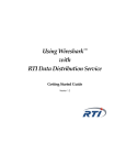
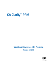
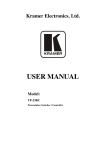
Kramer Electronics, Ltd.
USER MANUAL
Models:
VS-88A, VS-88V, SD-7588A, SD-7588V, RC-8000
88 Series
Contents
Contents
1
2
3
3.1
3.2
4
4.1
4.2
4.3
4.4
4.5
5
6
6.1
6.2
6.3
6.4
6.5
7
7.1
Introduction
Getting Started
Overview
The 88 Series
High Quality Performance Recommendations
Your Matrix Switchers
Your VS-88A 8x8 Balanced Audio Matrix Switcher
Your VS-88V 8x8 Video Matrix Switcher
Your SD-7588A 8x8 Digital Audio Matrix Switcher
Your SD-7588V 8x8 SDI Matrix Switcher
Your RC-8000 Remote Controller
Installing in a Rack
Connecting Your Matrix Switchers
Dipswitch Settings
Connecting a Standalone Unit
Connecting Several Units with/without the Remote Controller
Connecting Several Units and the PC
Connecting a Component, Y/C, RGBS or RGBHV Switcher
Understanding the Modes
About the System Modes
1
1
2
2
2
3
3
6
9
12
15
18
19
19
20
20
22
23
24
24
7.1.1
7.1.2
Standalone Mode
IN SYSTEM Mode
24
24
7.2
About the Confirmation Modes
24
7.2.1
7.2.2
AT ONCE Mode
CONFIRM Mode
25
25
8
8.1
Operation
Technical Information
26
26
8.1.1
8.1.2
8.1.3
8.1.4
Setup Capacity
Switching the Power On
Timeout
System Settings Priority
26
26
26
27
8.2
Push Button Controls
27
8.2.1
8.2.2
8.2.3
Storing a Setting
Recalling a Setting
Locking and Unlocking Settings
27
27
28
9
Technical Specifications
30
i
Contents
Figures
Figure 1: VS-88A 8x8 Balanced Audio Matrix Switcher
Figure 2: VS-88V 8x8 Video Matrix Switcher
Figure 3: SD-7588A 8x8 Digital Audio Matrix Switcher
Figure 4: SD-7588V 8x8 SDI Matrix Switcher
Figure 5: RC-8000 Remote Controller
Figure 6: Rear Panel Dipswitches
Figure 7: RS-485 System Connection: Switchers and Remote Controllers
Figure 8: System Connection: Switchers and the PC
Figure 9: Component Switcher: VS-88V Group Connection
4
7
10
13
16
19
21
22
23
Tables
Table 1: VS-88A 8x8 Balanced Audio Matrix Switcher Features
Table 2: VS-88V 8x8 Video Matrix Switcher Features
Table 3: SD-7588A 8x8 Digital Audio Matrix Switcher Features
Table 4: SD-7588V 8x8 SDI Matrix Switcher Features
Table 5: RC-8000 Remote Controller Top Panel Features
Table 6: RC-8000 Remote Controller Rear Panel Features
Table 7: Rear Panel Dipswitches
Table 8: Machine # Dipswitch Settings
Table 9: Push Button Sequence Summary
Table 10: Technical Specifications for 88 Series
ii
5
8
11
14
17
17
19
19
30
31
KRAMER: SIMPLE CREATIVE TECHNOLOGY
Introduction
1
Introduction
Welcome to Kramer Electronics! Since 1981, Kramer Electronics has been
providing a world of unique, creative, and affordable solutions to the vast range
of problems that confront the video, audio, presentation, and broadcasting
professional on a daily basis. In recent years, we have redesigned and upgraded
most of our line, making the best even better! Our 500-plus different models
now appear in eight groups1 that are clearly defined by function.
Congratulations on purchasing your Kramer 88 Series switcher: VS-88A,
VS-88V, SD-7588A, and/or SD-7588V, and/or RC-8000 Remote Controller.
These products are ideal for:
Broadcast studios for on-air switching and signal routing
Production studios, for connecting various sources to acceptors
Non-linear editing suites and presentation applications
Each switcher package also includes the following items:
Power cord
Windows®-based Kramer control software2
This user manual3
2
Getting Started
We recommend that you:
Unpack the equipment carefully and save the original box and packaging
materials for possible future shipment
Review the contents of this user manual
Use Kramer high performance high resolution cables4
1 GROUP 1: Distribution Amplifiers; GROUP 2: Video and Audio Switchers, Matrix Switchers and Controllers; GROUP 3:
Video, Audio, VGA/XGA Processors; GROUP 4: Interfaces and Sync Processors; GROUP 5: Twisted Pair Interfaces;
GROUP 6: Accessories and Rack Adapters; GROUP 7: Scan Converters and Scalers; and GROUP 8: Cables and Connectors
2 Downloadable from our Web site at http://www.kramerelectronics.com
3 Download up-to-date Kramer user manuals from the Internet at this URL: http://www.kramerelectronics.com
4 The complete list of Kramer cables is on our Web site at http://www.kramerelectronics.com
1
Overview
3
Overview
The 88 Series is a group of 8x8 Vertical Interval Matrix Switchers1 and a
Remote Control Panel for video/stereo audio/data signals that support the
simultaneous connection of one or more inputs to several outputs2. Vertical
Interval Switching3 ensures an undisturbed picture transition. The major
innovation with the 88 Series is the ability to switch different kinds of signals
simultaneously. Section 3.1 outlines the 88 Series and section 3.2 includes
recommendations for achieving high quality performance.
3.1 The 88 Series
The 88 Series includes the following items:
VS-88A (stereo audio matrix switcher for analog balanced audio)
VS-88V (video matrix switcher for analog composite video)
SD-7588A (audio matrix switcher for digital audio)
SD-7588V (video matrix switcher for digital video)
RC-8000 (remote controller for use with the switchers)
3.2 High Quality Performance Recommendations
Achieving high quality performance means:
Connecting only good quality connection cables, thus avoiding interference,
deterioration in signal quality due to poor matching, and elevated noise levels
(often associated with low quality cables)
Using good quality sockets and connectors for the sources and acceptors to
avoid signal path breaks4. Aim for Zero Ohm connection resistance and ensure
that sockets and connectors match the required impedance (75 ohms in video)
Avoiding interference from neighboring electrical appliances that may
adversely influence signal quality. Install unbalanced audio and video lines5
(even though the cables are shielded) away from mains carrying cables, electric
motors, and transmitters
1 Switching is implemented during the vertical interval period according to the SMPTE RP-168 standard, when using
synchronized SDI sources
2 However, you cannot connect two or more inputs to a single output
3 Frequently used when recording or transmitting a video program involving several video sources
4 Poor quality connectors tend to rust, which may cause breaks
5 Balanced audio lines are less prone to interference
2
KRAMER: SIMPLE CREATIVE TECHNOLOGY
Your Matrix Switchers
Positioning the switcher correctly. Each switcher is housed in a professional
19-inch rack mountable enclosure, requiring one vertical rack space per
product1. The standard 19-inch (IU) EIA rack assembly requires no specific
spacing above or below the unit for ventilation
4
Your Matrix Switchers
This section describes the products2 in the 88 Series range that can function
separately3 or switch together in the same manner in the In System mode4.
4.1 Your VS-88A 8x8 Balanced Audio Matrix Switcher
The VS-88A is a high performance 8x8 stereo audio matrix switcher for
balanced audio stereo signals using detachable terminal block connectors. In
addition, the VS-88A:
Is a true matrix switcher, enabling the user to simultaneously route any input to
any or all outputs
Delivers excellent audio performance ensuring that it remains transparent in
almost any audio application
Is controllable via the front panel buttons as well as the built-in RS-232 and
RS-485 interfaces
Includes 15 preset memory locations for quickly and easily accessing the most
frequently used configurations
May be used with the RC-8000, an optional remote controller (see section 0)
Functions as a standalone unit as well as part of a Kramer multi-signal switcher
system5
Figure 1 and Table 1 define the VS-88A:
1 To install a switcher in a rack, see section 5
2 Switchers in the 88 Series share identical front panel controls. Video switchers with the suffix V, have rear panel BNC
connectors. Audio switchers with the suffix A, have rear panel detachable terminal block connectors
3 Standalone
4 Section 7 describes the different modes
5 Which includes digital and analog video, digital and analog audio and RS-422 control switchers. When integrated in a
system, it switches together with the video during the vertical interval, thus supporting true IN SYSTEM mode
3
Your Matrix Switchers
Figure 1: VS-88A 8x8 Balanced Audio Matrix Switcher
4
KRAMER: SIMPLE CREATIVE TECHNOLOGY
Your Matrix Switchers
Table 1: VS-88A 8x8 Balanced Audio Matrix Switcher Features
#
Feature
1
2
3
POWER Switch
ALL Button
OFF Button
4
SELECT
Buttons
5
STO Button
6
RCL Button
7
IN SYSTEM Button
8
TAKE Button
(TAKE = CONFIRM)
OUTPUT labels
INPUT Status Display
INPUT Terminal Block
Connectors
OUTPUT Terminal
Block Connectors
MACHINE #
RS-485 Connector
9
10
11
12
13
14
15
16
IN
OUT
Function
Illuminated switch supplying power to the unit
1
Pressing ALL before pressing an INP button, connects that input to all outputs
Pressing OFF after pressing an OUT button disconnects that output from the
inputs. To turn off the connections, press the ALL button and then the OFF
button
Select the output to which the input is switched (from 1 to 8)
Select the input to switch to the output (from 1 to 8)
Pressing STO (Store) followed by an output button stores the current setting
2
(refer to section 8.2.1)
Pressing the RCL (Recall) button and the corresponding OUT key recalls a
setup. Press the RCL button again to implement the new status (refer to section
8.2.2)
3
Pressing IN SYSTEM twice , switches between the Standalone mode (in which
the switcher implements any action independently from the others) and the In
System mode (in which all switchers implement the same action simultaneously)
4
Pressing TAKE toggles the mode between the CONFIRM mode and the AT
ONCE mode (user confirmation per action is unnecessary)
Identifies a connection between the output and the input shown below it
Displays the selected input switched to the output (marked above each input)
Connect to balanced stereo audio sources (from 1 to 8)
Connect to balanced stereo audio acceptors (from 1 to 8)
Dipswitches setup (refer to section 6.1)
RS-485 detachable terminal block port. Pins # 1 to # 3 are for RS 485 and pin #
4 is for vertical sync distribution5 as Figure 7 illustrates
Power Connector with AC connector enabling power supply to the unit
Fuse
RS-232 OUT 9-pin
Connects to the RS-232 IN 9-pin D-sub port of the next unit in the daisy-chain
D-sub Connector
connection6
7
RS-232 IN 9-pin
Connects to PC or Remote Controller
D-sub Connector
1 For example, press ALL and then Input button # 2 to connect input # 2 to all the outputs
2 For example, press STO and then the Output button # 3 to store in Setup # 3
3 After pressing IN SYSTEM once, it blinks
4 When in Confirm mode, the TAKE button illuminates
5 The 88 Series RS-485 connector has 4 pins, and the remote controller RS-485 connector has just 3 pins
6 If the unit is the final unit in the daisy-chain connection, no termination is required
7 If the unit is not the first unit in the line, connects to the RS-232 OUT 9-PIN D SUB port of the previous unit in the line
5
Your Matrix Switchers
4.2 Your VS-88V 8x8 Video Matrix Switcher
The VS-88V is a high performance 8x8 composite video matrix switcher. In
addition, the VS-88V:
Is a true matrix switcher, enabling the user to simultaneously route any input to
any or all outputs
Supports more than 200MHz video bandwidth
Switches during the vertical interval1
Accepts analog video as the external source for its vertical interval trigger
Is controllable via the front panel buttons as well as the built-in RS-232 and
RS-485 interfaces
Includes 15 preset memory locations for quickly and easily accessing the most
frequently used configurations
May be used with the RC-8000, an optional remote controller (see section 0)
Functions as a standalone unit as well as part of a Kramer multi-signal switcher
system2
Can be combined as part of a group of VS-88V switchers that comprise a
component switcher3
Figure 2 and Table 2 define the VS-88V:
1 Transitions are glitch-free when sources share a common reference sync
2 Which includes digital and analog video, digital and analog audio, and RS-422 control switchers. When integrated into a
system, it can provide the rest of switchers with the vertical interval trigger
3 Refer to section 6.5 and Figure 9 on page 23
6
KRAMER: SIMPLE CREATIVE TECHNOLOGY
Your Matrix Switchers
Figure 2: VS-88V 8x8 Video Matrix Switcher
7
Your Matrix Switchers
Table 2: VS-88V 8x8 Video Matrix Switcher Features
#
Feature
1
2
POWER Switch
ALL Button (ALL= All Outputs)
3
OFF Button (OFF= All Inputs)
4
5
6
SELECT OUT Buttons
SELECT IN Buttons
STO Button
7
RCL Button
8
IN SYSTEM Button
9
10
11
TAKE Button
(TAKE = CONFIRM)
OUTPUT labels
INPUT Status Display
12
Input Status LEDs
13
14
15
16
17
INPUTS BNC Connectors
OUTPUTS BNC Connectors
SYNC BNC Connectors
75 ohms Button
RS-232 IN 9-pin D-sub
Connector
MACHINE # Dipswitches
RS-485 Connector
18
19
20
9
Power Connector with Fuse
RS-232 OUT 9-pin D-sub
Connector
Function
Illuminated switch supplying power to the unit
Pressing ALL before pressing an INPUT button, connects that input to
1
all outputs
Pressing OFF after pressing an OUTPUT button disconnects that output
from the inputs. To turn off the connections, press the ALL button and
then the OFF button
Select the output to which the input is switched (from 1 to 8)
Select the input to switch to the output (from 1 to 8)
Pressing STO (STORE) followed by an output button stores the current
2
setting (refer to section 8.2.1)
Pressing the RCL (Recall) button and the corresponding OUT key
recalls a setup. Press the RCL button again to implement the new
status (refer to section 8.2.2)
3
Pressing IN SYSTEM twice , switches between the Standalone mode
(in which the switcher implements any action independently from the
others) and the In System mode (in which all switchers implement the
same action simultaneously)
Pressing TAKE toggles the mode between the CONFIRM mode4 and
the AT ONCE mode (user confirmation per action is unnecessary)
Identifies a connection between the output and the input shown below it
Displays the selected input switched to the output (marked above each
input)
Illuminate when the input signal is presented on a corresponding line
and complies with the SDI standard
Connect to the video sources (from 1 to 8)
Connect to the video outputs (from 1 to 8)
For looping to external video sync input
Controls loop termination5
Connects to PC or Remote Controller6
For setup of the machine number (refer to section 6.1)
RS-485 detachable terminal block port. Pins # 1 to # 3 are for RS 485
and pin # 4 is for vertical sync distribution7
AC connector enabling power supply to the unit
Connects to the RS-232 IN 9-pin D-sub port of the next unit in the daisychain connection 8
1 For example, press ALL and then Input button # 2 to connect input # 2 to all the outputs
2 For example, press STO and then the Output button # 3 to store in Setup # 3
3 After pressing IN SYSTEM once, it blinks
4 When in Confirm mode, the TAKE button illuminates
5 Push in to terminate the SYNC line. Push out when the line extends to another unit
6 If the unit is not the first unit in the line, connects to the RS-232 OUT 9-PIN D SUB port of the previous unit in the line
7 The 88 Series RS-485 connector has 4 pins, and the Remote Controller RS-485 connector has just 3 pins
8 If the unit is the final unit in the daisy-chain connection, no termination is required
8
KRAMER: SIMPLE CREATIVE TECHNOLOGY
Your Matrix Switchers
4.3 Your SD-7588A 8x8 Digital Audio Matrix Switcher
The SD-7588A is a high performance multi-standard 8x8 digital audio matrix
switcher that is adjustment-free, cable-equalized and reclocking. In addition,
the SD-7588A:
Provides automatic equalization for losses on 110 twisted pair cable
Reclocks each output to provide eight low-jitter digital outputs
Supports AES/EBU, IEC 958, S/PDIF and EIAJ CP340/1201 professional and
consumer formats with sampling frequencies up to 96kHz
Comes with all inputs and outputs transformer coupled, supporting 110
impedance twisted pair cable on detachable terminal block connectors
Is controllable via the front panel buttons as well as the built-in RS-232 and
RS-485 interfaces
Includes 15 preset memory locations for quickly and easily accessing the most
frequently used configurations
May be used with the RC-8000, an optional remote controller (see section 0)
Functions as a standalone unit as well as part of a Kramer multi-signal switcher
system1
Figure 3 and Table 3 define the SD-7588A:
1 Which includes digital and analog video, digital and analog audio and RS-422 control switchers. When integrated in a
system, it switches together with the video during the vertical interval, thus supporting true IN SYSTEM mode
9
Your Matrix Switchers
Figure 3: SD-7588A 8x8 Digital Audio Matrix Switcher
10
KRAMER: SIMPLE CREATIVE TECHNOLOGY
Your Matrix Switchers
Table 3: SD-7588A 8x8 Digital Audio Matrix Switcher Features
#
1
2
3
Feature
Power Switch
ALL Button
(ALL= All Outputs)
OFF Button
(OFF= All Inputs)
Pressing OFF after pressing an OUTPUT button disconnects that output from
the inputs. To turn off the connections, press the ALL button and then the OFF
button
Select the output to which the input is switched
Select the input to switch to the output
Pressing STO (STORE) followed by an output button stores the current setting
2
(refer to section 8.2.1)
Pressing the RCL (Recall) button and the corresponding OUT key recalls a
setup. Press the RCL button again to implement the new status (refer to
section 8.2.2)
3
Pressing IN SYSTEM twice , switches between the Standalone mode (in
which the switcher implements any action independently from the others) and
the In System mode (in which all switchers implement the same action
simultaneously)
4
Pressing TAKE toggles the mode between the CONFIRM mode and the AT
ONCE mode (user confirmation per action is unnecessary)
4
SELECT
Buttons
5
STO Button
6
RCL Button
7
IN SYSTEM Button
8
10
TAKE Button
(TAKE = CONFIRM)
OUTPUT labels
INPUT Status Display
INPUT STATUS LEDs
11
12
13
14
INPUTS Connectors
OUTPUTS Connectors
MACHINE # Dipswitches
RS-485 Connector
15
Power Connector with
Fuse
RS-232 OUT 9-pin D-sub Connects to the RS-232 IN 9-pin D-sub port of the next unit in the daisy-chain
Connector
connection 6
RS-232 IN 9-pin D-sub
Connects to PC or Remote Controller7
Connector
9
16
17
OUT
IN
Function
Illuminated switch supplying power to the unit
Pressing ALL before pressing an INPUT button, connects that input to all
1
outputs
Identifies a connection between the output and the input shown below it
Displays the selected input switched to the output (marked above each input)
Illuminate when the input signal is presented on a corresponding line and
complies with the AES/EBU standard
Audio inputs
Audio outputs
For setup of the machine number (refer to section 6.1)
RS-485 detachable terminal block port. Pins # 1 to # 3 are for RS 485 and pin
# 4 is for vertical sync distribution5
AC connector enabling power supply to the unit
1 For example, press ALL and then Input button # 2 to connect input # 2 to all the outputs
2 For example, press STO and then the Output button # 3 to store in Setup # 3
3 After pressing IN SYSTEM once, it blinks
4 When in Confirm mode, the TAKE button illuminates
5 The 88 Series RS-485 connector has 4 pins, and the Remote Controller RS-485 connector has just 3 pins
6 If the unit is the final unit in the daisy-chain connection, no termination is required
7 If the unit is not the first unit in the line, connects to the RS-232 OUT 9-pin D-sub port of the previous unit in the line
11
Your Matrix Switchers
4.4 Your SD-7588V 8x8 SDI Matrix Switcher
The SD-7588V is a high performance multi-standard 8x8 serial digital video
matrix switcher that is adjustment-free, cable-equalized and reclocking. In
addition, the SD-7588V:
Provides automatic equalization for losses on 75 coaxial cable, and reclocks
each output to provide eight low-jitter serial digital outputs
Automatic standard recognition
Operates with both 10-bit and 8-bit video, automatically recognizing the word
length
Accepts analog video as the external source for its vertical interval trigger
Is controllable via the front panel buttons as well as the built-in RS-232 and
RS-485 interfaces
Includes 15 preset memory locations for quickly and easily accessing the most
frequently used configurations
May be used with the RC-8000, an optional remote controller (see section 0)
Functions as a standalone unit as well as part of a Kramer multi-signal switcher
system1
Figure 4 and Table 4 define the SD-7588V:
1 Which includes digital and analog video, digital and analog audio, and RS-422 control switchers. When integrated into a
system, it provides the rest of switchers with the vertical interval trigger
12
KRAMER: SIMPLE CREATIVE TECHNOLOGY
Your Matrix Switchers
Figure 4: SD-7588V 8x8 SDI Matrix Switcher
13
Your Matrix Switchers
Table 4 defines the features and functions of the SD-7588V:
Table 4: SD-7588V 8x8 SDI Matrix Switcher Features
#
1
2
3
Feature
Power Switch
ALL Button
(ALL= All Outputs)
OFF Button
(OFF= All Inputs)
Function
Illuminated switch supplying power to the unit
Pressing ALL before pressing an INPUT button, connects that input to all
1
outputs
4
5
6
SELECT Buttons
OUT
IN
7
RCL Button
8
IN SYSTEM Button
9
10
11
TAKE Button
(TAKE = CONFIRM)
OUTPUT Labels
INPUT Status Display
12
INPUT STATUS LEDs
13
14
15
16
17
18
INPUT BNC Connectors
OUTPUT BNC Connectors
SYNC BNC Connectors
75 OHMS Button
MACHINE #
RS-485 Connector
19
RS-232
9-pin D-sub
Connectors
20
Power Connector with Fuse
STO Button
IN
OUT
Pressing OFF after pressing an OUTPUT button disconnects that output
from the inputs. To turn off the connections, press the ALL button and then
the OFF button
Select the output to which the input is switched
Select the input to switch to the output
Pressing STO (STORE) followed by an output button stores the current
2
setting (refer to section 8.2.1)
Pressing the RCL (Recall) button and the corresponding OUT key recalls a
setup. Press the RCL button again to implement the new status (refer to
section 8.2.2)
3
Pressing IN SYSTEM twice , switches between the Standalone mode (in
which the switcher implements any action independently from the others)
and the In System mode (in which all switchers implement the same action
simultaneously)
4
Pressing TAKE toggles the mode between the CONFIRM mode and the
AT ONCE mode (user confirmation per action is unnecessary)
Identifies a connection between the output and the input shown below it
Displays the selected input switched to the output (marked above each
input)
Illuminate when the input signal is presented on a corresponding line and
complies with the SDI standard
Connect to the composite video sources (from 1 to 8)
Connect to the composite video acceptors (from 1 to 8)
For looping to external video sync input
Controls loop termination5
Dipswitches for setup of the machine number (refer to section 6.1)
RS-485 detachable terminal block port. Pins # 1 to # 3 are for RS 485 and
pin # 4 is for vertical sync distribution6
Connects to PC or Remote Controller7
Connects to the RS-232 IN 9-pin D-sub port of the next unit in the daisychain connection 8
AC connector enabling power supply to the unit
1 For example, press ALL and then Input button # 2 to connect input # 2 to all the outputs
2 For example, press STO and then the Output button # 3 to store in Setup # 3
3 After pressing IN SYSTEM once, it blinks
4 When in Confirm mode, the TAKE button illuminates
5 Push in to terminate the SYNC line. Push out when the line extends to another unit
6 The 88 Series RS-485 connector has 4 pins, and the Remote Controller RS-485 connector has just 3 pins
7 If the unit is not the first unit in the line, connects to the RS-232 OUT 9-pin D-sub port of the previous unit in the line
8 If the unit is the final unit in the daisy-chain connection, no termination is required
14
KRAMER: SIMPLE CREATIVE TECHNOLOGY
Your Matrix Switchers
4.5 Your RC-8000 Remote Controller
The RC-8000 is an optional remote controller for accessing and controlling
switchers in the 88 Series. In addition, the RC-8000:
Supports1 the creation of any configuration that consists of a PC, an unlimited
number of remote controllers, and up to any2 eight 88 Series switchers,
activating all the functions of the connected devices, individually or grouped
Includes eight illuminated MACHINE IN SYSTEM buttons that enable
toggling between the standalone and the IN SYSTEM modes of any switcher,
and viewing the status and control of the corresponding switcher3
Includes eight bright LED displays showing the status of any standalone or IN
SYSTEM matrix switcher
Continuously scrutinizes the status of the connecting RS-485 line
Receives its power from a 12V DC source (also useful for field operation)
Can be desktop-mounted (by resting it on its base or attaching it to the desktop)
or built into a controlling table
Figure 5 illustrates the front and rear panels of the RC-8000 Remote
Controller:
1 Using its built-in RS-485 interface
2 You can control different types of machines in a single configuration
3 That is, the switcher with the same MACHINE # as the MACHINE IN SYSTEM #
15
Your Matrix Switchers
Rear Panel Sockets
Power
+12v DC
RS-485
-+G
Figure 5: RC-8000 Remote Controller
16
KRAMER: SIMPLE CREATIVE TECHNOLOGY
Your Matrix Switchers
Table 5 and Table 6 define the features and functions of the RC-8000:
Table 5: RC-8000 Remote Controller Top Panel Features
Feature
MACHINE IN
SYSTEM Buttons
2
3
INPUT Buttons
Comm. Error LED
4
5
9
OUTPUT Buttons
OUTPUT
labels
INPUT
Display
POWER LED (green)
TAKE Button
(TAKE = CONFIRM)
STO Button
10
RCL Button
11
ALL Button
(ALL= All Outputs)
Three Screws
6
7
8
12
13
STATUS
#
1
OFF Button
(OFF= All Inputs)
Function
Enable toggle between the standalone and the IN SYSTEM modes of any
1
switcher, and viewing the status and control of the corresponding switcher (from
1 to 8)
Select the input to switch to the output (from 1 to 8)
The Comm. Error red LED illuminates when a connection between the remote
controller and a switcher fails2
Select the output to which the input is switched (from 1 to 8)
Identifies a connection between the output and the input shown below it
Displays the selected input switched to the output (marked above each input)
Illuminates when power is activated
Pressing TAKE toggles the mode between the CONFIRM mode3 and the AT
ONCE mode (user confirmation per action is unnecessary)
Pressing STO (STORE) followed by an output button stores the current setting
(refer to section 8.2.1)
Pressing the RCL (Recall) button and the corresponding OUT key recalls a setup.
Press the RCL button again to implement the new status (refer to section 8.2.2)
Pressing ALL before pressing an INPUT button, connects that input to all outputs4
Removing the three screws separates the base platform. By drilling three holes in
the desktop you can screw the remote controller directly in place
Pressing OFF after pressing an OUTPUT button disconnects that output from the
inputs. To turn off the connections, press the ALL button and then the OFF button
Table 6: RC-8000 Remote Controller Rear Panel Features
#
1
2
Feature
Power Socket
RS-485 Connector
Function
+12V DC connector enabling power supply to the unit
RS-485 detachable terminal block port
1 Refer to section 7
2 For example, the switcher is not connected at all, or connected, but without power
3 When in Confirm mode, the TAKE button illuminates
4 For example, press ALL and then Input button # 2 to connect that input to all outputs
17
Installing in a Rack
5
Installing in a Rack
This section describes what to do before installing in a rack and how to rack
mount.
Before Installing in a Rack
Before installing in a rack, be sure that the environment is
within the recommended range:
Operating temperature range +5º to +45º C (41º to 113º F)
Operating humidity range
10 to 90% RHL, non-condensing
Storage temperature range
-20º to +70º C (-4º to 158º F)
Storage humidity range
5 to 95% RHL, non-condensing
How to Rack Mount
To rack-mount a machine:
1. Attach both ear brackets to the
machine. To do so, remove the
screws from each side of the
machine (3 on each side), and
replace those screws through the
ear brackets.
CAUTION!!
When installing on a 19" rack, avoid hazards by taking
care that:
1. It is located within the recommended environmental
conditions, as the operating ambient temperature of a
closed or multi unit rack assembly may exceed the
room ambient temperature.
2. Once rack mounted, enough air will still flow around
the machine.
3. The machine is placed straight in the correct
horizontal position.
4. You do not overload the circuit(s). When connecting
the machine to the supply circuit, overloading the
circuits might have a detrimental effect on overcurrent
protection and supply wiring. Refer to the appropriate
nameplate ratings for information. For example, for
fuse replacement, see the value printed on the
product label.
5. The machine is earthed (grounded) in a reliable way
and is connected only to an electricity socket with
grounding. Pay particular attention to situations where
electricity is supplied indirectly (when the power cord
is not plugged directly into the socket in the wall), for
example, when using an extension cable or a power
strip, and that you use only the power cord that is
supplied with the machine.
18
2. Place the ears of the machine
against the rack rails, and insert the
proper screws (not provided)
through each of the four holes in the
rack ears.
Note that:
In some models, the front panel
may feature built-in rack ears
Detachable rack ears can be
removed for desktop use
Always mount the machine in the
rack before you attach any cables
or connect the machine to the
power
If you are using a Kramer rack
adapter kit (for a machine that is not
19"), see the Rack Adapters user
manual for installation instructions
(you can download it at:
http://www.kramerelectronics.com)
KRAMER: SIMPLE CREATIVE TECHNOLOGY
Connecting Your Matrix Switchers
6
Connecting Your Matrix Switchers
This section describes how to:
Set the dipswitches (refer to section 6.1)
Connect a standalone unit (refer to section 6.2)
Connect several units1 with/without the remote controller (refer to section 6.3)
Connect several units and the PC (refer to section 6.4)
Connect a component switcher (refer to section 6.5)
6.1 Dipswitch Settings
Each 88 Series switcher includes a rear panel set of six dipswitches, as Figure
6, Table 7 and Table 8 define.
Figure 6: Rear Panel Dipswitches
Table 7: Rear Panel Dipswitches
Dipswitch #
Function:
1-4
Set the MACHINE NUMBER (refer to Table 8)
5
Disables use of the IN SYSTEM button
(OFF = enables the IN SYSTEM button; ON = disables the IN SYSTEM button)
6
Enables a reply from the unit after it receives an RS-232 / RS-485 command
(OFF = disables reply2 ;ON = enables reply)
Table 8: Machine # Dipswitch Settings
MACHINE #
DIPSWITCH
1
2
1
OFF ON
2
ON
3
4
ON
ON
OFF ON
ON
3
OFF OFF ON
ON
4
ON
ON
OFF ON
5
OFF ON
OFF ON
6
ON
7
OFF OFF OFF ON
8
ON
OFF OFF ON
ON
ON
OFF
1 With the 88 Series, you cannot connect two separate IN SYSTEM mode systems as one combined system
2 Helpful, for example, when using three composite video switchers to form one component video switcher
19
Connecting Your Matrix Switchers
6.2 Connecting a Standalone Unit
To connect a standalone unit:
Connect the power supply
Connect the audio and/or video input and output cables
Connect the video reference input for VS-88V and/or SD-7588V
Set dipswitch # 1 OFF and dipswitches # 2, 3, 4, 5 and 6 ON (see section 6.1)
The IN SYSTEM button is non responsive
6.3 Connecting Several Units with/without the Remote Controller
To connect several units with or without the remote controller:
Connect the power supply
Connect the audio and/or video input and output cables
Connect the video reference input for VS-88V or SD-7588V
In a system with more than one video switcher (either VS-88V or SD-7588V),
connect all video switchers to the video reference by looping between the sync
BNC connectors
Set the dipswitches for the different MACHINE # (1 to 8) for each machine
and set dipswitch # 5 OFF and dipswitch # 6 ON
Connect all the 4 terminals to the RS-485 interface connectors
Operate the front panel controls of any switcher
Figure 7 illustrates a typical system connection:
20
KRAMER: SIMPLE CREATIVE TECHNOLOGY
Connecting Your Matrix Switchers
Figure 7: RS-485 System Connection: Switchers and Remote Controllers
You can connect up to 24 remote controllers and up to 8 switchers per
system. However, when connecting less than 8 switchers, you can connect
more remote controllers1.
1 RS-485 connection supports up to 32 devices, that is, switchers and remote controllers. For example, when connecting 2
switchers per system, you can connect up to 30 remote controllers
21
Connecting Your Matrix Switchers
6.4 Connecting Several Units and the PC
To connect several units and the PC:
Connect the power supply
Connect the audio and/or video input and output cables
Connect the video reference input (for video) for VS-88V and/or SD-7588V
Set the dipswitches for the different MACHINE #. Set dipswitch # 5 OFF and
dipswitch # 6 ON
Switchers in a daisy chain arrangement1 using the RS-232 IN and RS-232
OUT 9-pin D-sub connectors should be connected using a flat-cable, or with at
least the three wires (pins # 2, # 3 and # 5)2. Do not use a null-modem
adapter. Assign PC port to 9600, N, 8, and 1
Figure 8 illustrates a typical system connection with both3 the RS-232 and the
RS-485 connected in a parallel line:
Switcher # 1
IN
RS-232
OUT
IN
RS-232
OUT
IN
RS-232
OUT
…
Switcher # 8
Figure 8: System Connection: Switchers and the PC
1 The 88 Series firmware complies with Kramer Protocol-2000 (version 3.1 and higher)
2 Make one-to-one connections (that is, uncrossed)
3 Often the PC has no RS-485 Com port and so both are required simultaneously
22
KRAMER: SIMPLE CREATIVE TECHNOLOGY
Connecting Your Matrix Switchers
1
6.5 Connecting a Component , Y/C, RGBS or RGBHV Switcher
A component2 switcher consists of three VS-88V switchers, interconnected as
one group, with one of the switchers set as the Master. A component switcher
can function in the IN SYSTEM or standalone mode. Similarly, you can
configure two VS-88V switchers for Y/C (s-Video), four VS-88V switchers
for RGBS or five VS-88V switchers for RGBHV.
To set the VS-88V switchers in the group to operate as a single component
switcher, do the following with every switcher in the group:
Set the same MACHINE # for each switcher (for example, MACHINE # 2)
Set dipswitch # 5 OFF
Set dipswitch # 6 OFF (except on the Master, set Dipswitch # 6 ON)
Except for the Master (whose LEDs illuminate and front panel controls remain
unlocked), the LEDs on all switchers in the group are dimmed, and their front
panel controls are locked3
Figure 9 illustrates a component switcher that consists of a group of 3
VS-88V switchers:
Figure 9: Component Switcher: VS-88V Group Connection
1 For RGB or YUV (Y, B-Y, R-Y)
2 Video signal in component form offers the highest professional video quality, superior to composite or s-Video
3 After initially powering up the component switcher, if some of its switchers remain in a different status, press the ALL
button followed by the OFF button on the Master to reset all the connections prior to normal operation
23
Understanding the Modes
7
Understanding the Modes
This section describes the different system and confirmation modes.
7.1 About the System Modes
By default, a switcher starts in the standalone mode and the IN SYSTEM key
does not illuminate. Pressing the IN SYSTEM key twice toggles to the IN
SYSTEM mode.
This section describes the Standalone and the IN SYSTEM modes, as
follows:
7.1.1
Standalone Mode
In the standalone mode:
The switcher implements actions independently and separately from the others
Upon starting the system, only one MACHINE IN SYSTEM # illuminates on
the remote controller
7.1.2
IN SYSTEM Mode
In the IN SYSTEM mode:
Several switchers with different kinds of signals are connected as a system
operating as a universal switcher1
More than one MACHINE IN SYSTEM # illuminates2 to indicate the units
that are connected as part of a system. Each MACHINE IN SYSTEM # for
those IN SYSTEM units will not illuminate. However, on each of the IN
SYSTEM units, the respective IN SYSTEM button continues to illuminate
Any executed action affects all units in the system
7.2 About the Confirmation Modes
By default, the unit starts in the AT ONCE mode, that is, if an OUT-IN
combination is pressed, it will be implemented immediately. Pressing the
TAKE button twice, toggles between the CONFIRM and the AT ONCE
modes.
This section describes the CONFIRM and the AT ONCE modes, as follows:
1 Each switches in the same order according to the entered command, with one or more of them following the other units
2 The IN SYSTEM button on each unit also illuminates
24
KRAMER: SIMPLE CREATIVE TECHNOLOGY
Understanding the Modes
7.2.1
AT ONCE Mode
In the AT ONCE mode:
You save time
Actions require no user confirmation
Execution is immediate
No protection is offered to prevent the implementation of a wrongly entered
action
7.2.2
CONFIRM Mode
In the CONFIRM mode:
You have a method to help avoid making a mistake
Every action requires user confirmation
Execution is delayed until the user confirms the action
Protection is offered to prevent erroneous switching
25
Operation
8
Operation
This section describes the hardware of the machine and the operation of its
front panel controls.
For instructions on using the Windows®-based Kramer control software,
refer to the separate user manual1, Kramer Control Software.
8.1 Technical Information
This section describes setup capacity, switching the power on, timeout and
the system settings.
8.1.1
Setup Capacity
From every switcher you can store up to 8 setups. From the PC you can store
up to 15 setups.
8.1.2
Switching the Power On
To switch the power on at all the switchers, do the following:
1. Verify, via the automatic self-test, that all switchers function correctly.
2. Check the firmware version number indicated by the two fast blinking
digits on the display2.
To switch the power on at the remote controller, do the following:
1. Attach the power adapter plug to the power socket on the remote
controller.
2. Verify, via the automatic self-test, that all switchers and the remote
controller function correctly.
3. The Comm. Error LED will illuminate to indicate a problem3, if at all,
with any switcher.
8.1.3
Timeout
By design, every push button operation is subject to a 30 second timeout.
Failure to fully execute an action within 30 seconds will necessitate restarting
that action whilst the LED display will show the previous state.
1 Included on the CD-ROM in .pdf format
2 For example, the digits 10 indicate version 1.0
3 For example, if a switcher is not connected, or its power is switched off
26
KRAMER: SIMPLE CREATIVE TECHNOLOGY
Operation
8.1.4
System Settings Priority
The design excludes any priority1. Any operator2 can always override the
previous system settings. For example, in Figure 7: RS-485 System
Connection: Switchers and Remote Controllers, the system setting
implemented by the operator of Remote Controller # 24 will be the current
system setting until the operator of say, Remote Controller # 5, implements a
different system setting.
8.2 Push Button Controls
This section describes how to store, recall and lock/unlock settings.
8.2.1
Storing a Setting
To store a setting, do the following:
1. Press the STO button. The STO button blinks.
2. Press the Output #. The LED Output display # blinks3.
3. Press the STO button again. The memory stores the data.
4. The LED display returns to its previous state4.
8.2.2
Recalling a Setting
To recall a setting, do the following:
1. Press the RCL button. The RCL button blinks.
2. Press the Output #. The LED Output display # blinks5, displaying what
was previously stored.
3. Press the RCL button again. This recalls the stored data.
By design6, you cannot recall data that is stored in a particular unit from a
different unit. Each unit, even when set to the IN SYSTEM mode, stores its
own data separately.
1 Between any or all of the following: remote controllers, front panel controls and a PC
2 Whether he operates a remote controller, a set of front panel controls or a PC
3 At this stage, pressing a different # changes the Output #
4 Nothing changes in the setup
5 At this stage, pressing a different # changes the Output #
6 On one occasion the same unit can function in the standalone mode, and on another occasion in the IN SYSTEM mode
27
Operation
8.2.3
Locking and Unlocking Settings
The remote controllers and the PC include a flexible locking1 mechanism for
safeguarding settings on switchers. To prevent changing the settings
accidentally2, lock your switchers. Unlocking releases3 the protection
mechanism.
From any remote controller you can lock and unlock the following4:
A specific switcher
All switchers
That specific remote controller
From the PC5 you can lock and unlock the following:
A specific switcher
All switchers
Locking a specific remote controller does not lock any other remote
controller. To lock all the remote controllers, press the TAKE and the STO
push buttons on each remote controller separately. You cannot
simultaneously lock or unlock all the remote controllers from one remote
controller, or from the PC. When all switchers and remote controllers are
locked, the front panel switcher push buttons are inoperative. By design, only
specific6 remote controller push buttons will function, enabling the operator
to execute the unlock commands.
Section 8.2.3.1 describes how to lock the switcher and section 8.2.3.2
describes how to unlock the switcher. For a concise summary of the
locking/unlocking push button sequence, refer to Table 9 on page 30.
1 Locking means that the front panel is locked. In all other respects (for example, recall, changing input and output), the
switcher still operates via the remote controller and the PC
2 Especially if the system is complex and the switchers are stored on a rack in another room
3 Restarting (perhaps due to an electricity failure) a switcher or a remote controller also releases the protection mechanism
(without wiping out the switcher settings)
4 You cannot lock/unlock from a switcher
5 You cannot lock a PC
6 That is, TAKE, RCL, and ALL
28
KRAMER: SIMPLE CREATIVE TECHNOLOGY
Operation
8.2.3.1 Locking Switchers
To lock a specific switcher, do the following:
1. Press the TAKE button on the remote controller. The TAKE button
blinks.
2. Press the appropriate MACHINE IN SYSTEM # button on the remote
controller. The MACHINE IN SYSTEM # button blinks.
3. Press the STO button on the remote controller. The specific switcher
locks and the INPUT STATUS Display numbers on the switcher appear
dimmed.
To lock all switchers, do the following:
1. Press the TAKE button on the remote controller. The TAKE button
blinks.
2. Press the ALL button on the remote controller. The ALL button blinks.
3. Press the STO button on the remote controller. All the units lock and the
INPUT STATUS Display numbers on the switchers appear dimmed.
To lock a remote controller, do the following:
1. Press the TAKE button on the remote controller. The TAKE button
blinks.
2. Press the STO button on the remote controller. The remote controller
locks and the INPUT STATUS Display numbers on the remote controller
appear dimmed1.
8.2.3.2 Unlocking Switchers
To unlock a specific switcher, do the following:
1. Press the TAKE button on the remote controller. The TAKE button
blinks.
2. Press the appropriate MACHINE IN SYSTEM # button on the remote
controller. The MACHINE IN SYSTEM # button blinks.
3. Press the RCL button on the remote controller. The specific locked
switcher unlocks and the INPUT STATUS Display numbers on the
switcher no longer appear dimmed.
1 All other remote controllers remain unlocked
29
Technical Specifications
1
To unlock all switchers , do the following:
1. Press the TAKE button on the remote controller. The TAKE button
blinks.
2. Press the ALL button on the remote controller. The ALL button blinks.
3. Press the RCL button on the remote controller. All the switchers unlock
and the INPUT STATUS Display numbers on the switchers no longer
appear dimmed. The remote controller also unlocks.
To unlock a remote controller, do the following:
1. Press the TAKE button on the remote controller. The TAKE button
blinks.
2. Press the RCL button on the remote controller. The locked remote
controller unlocks and the INPUT STATUS Display numbers on the
remote controller no longer appear dimmed2.
Table 9: Push Button Sequence Summary
Lock
Unlock
Specific
Switcher
TAKE + MACHINE IN SYSTEM # + STO
TAKE + MACHINE IN SYSTEM # + RCL
All
Switchers
TAKE + ALL + STO
TAKE + ALL + RCL3L
Remote
Controller
TAKE + STO
TAKE + RCL
9
Technical Specifications
Table 10 lists the technical specifications for the 88 Series switchers.
1 Including the remote controller, if locked
2 All other remote controllers remain locked. You will need to unlock each remote controller separately
3 Unlocks all units, and in addition, the remote controller
30
KRAMER: SIMPLE CREATIVE TECHNOLOGY
Technical Specifications
Table 10: Technical Specifications for 88 Series
VS-88A
INPUTS:
8 balanced stereo audio, +4
dBm/33k on detachable terminal
blocks
OUTPUTS:
8 balanced audio stereo, +4
dBm/50 Vpp max) on detachable
terminal blocks
SAMPLING:
RESOLUTION:
STANDARDS:
VS-88V
SD-7588A
8 composite video, 1Vpp/75 on 8 AES/EBU digital audio, 110
BNCs, looping Analog sync inputs on detachable terminal blocks,
transformer coupled
1Vpp/75 on BNCs
8 composite video, 1Vpp/75 on 8 reclocked AES/EBU digital
audio, 110 on detachable
BNCs
terminal blocks, transformer
coupled
32, 44.1, 48, 96 kHz sampling
frequencies
Up to 24-bit, automatic according
to input resolution
AES/EBU, IEC 958, S/PDIF and
EIAJ CP340/1201
VIDEO BANDWIDTH:
200 MHz 3dB
VIDEO CROSSTALK:
< -50 dB @ 5 MHz
SD-7588V
8 x SMPTE - 259M serial video, 75
on BNCs; looping Analog sync
inputs on BNCs
8 reclocked SMPTE-259M outputs,
75 on BNCs
10-bit or 8-bit, automatic according
to input resolution
4fsc PAL, 4fsc NTSC, 4:2:2
(525/625), and 360Mb/s wide
screen (525/625)
>74 dB
VIDEO S/N:
<0.05%
DIFF. GAIN:
<0.03 Deg
DIFF. PHASE:
< 0.05%
K-FACTOR:
AUDIO BANDWIDTH: > 40 kHz; 0.3db
AUDIO CROSSTALK: < - 90 dB
AUDIO S/N:
> 90 dB unweighted (1Vpp)
AUDIO THD:
< 0.02% (1Vpp, 1kHz)
MAXIMAL AUDIO
EQUALIZATION:
DISPLAY:
CONTROLS:
20 dBm
Automatic up to 200mV eye
Automatic for up to 300m for 270
pattern
Mb/s using Belden 8281 cable
Current switcher status on eight 7-segment bright LEDs
Current switcher status on eight 7-segment bright LEDs. Signal presence
for each channel on front panel LEDs
22 front-panel touch switches, RS-232 and RS-485 control interface
31
VS-88A
VS-88V
SD-7588A
SD-7588V
During vertical interval from Analog sync
SWITCHING:
19-inch (W) x 7-inch (D) x 1U (H), rack mountable
DIMENSIONS:
AC-110V/60Hz, 220V/50Hz (switchable inside the unit)
POWER SOURCE:
WEIGHT:
3.5 kg. (7.8 lbs.) approx.
ACCESSORIES:
Power cord, Windows 95/98/NT TM control software
Universal, 85-264 VAC, 47-440 Hz,
25 VA max
RC-8000
INPUTS/OUTPUTS:
CONTROLS:
DIMENSIONS:
POWER SOURCE:
WEIGHT:
ACCESSORIES:
32
1x RS-485 connector on detachable terminal blocks
8 illuminated pushbuttons each assigned to a different controlled unit address. 8 out / 8 in / 5 operational pushbuttons similar to the 88 Series
8.5-inch (W) x 1.5-inch (D) x 5.5-inch (H), (21.6 cm x 3.8 cm x 14 cm)
12V DC, 200 mA
0.4 kg (0.9 lbs.) approx.
Wall Power supply
KRAMER: SIMPLE CREATIVE TECHNOLOGY
LIMITED WARRANTY
Kramer Electronics (hereafter Kramer) warrants this product free from defects in material and workmanship under the
following terms.
HOW LONG IS THE WARRANTY
Labor and parts are warranted for seven years from the date of the first customer purchase.
WHO IS PROTECTED?
Only the first purchase customer may enforce this warranty.
WHAT IS COVERED AND WHAT IS NOT COVERED
Except as below, this warranty covers all defects in material or workmanship in this product. The following are not covered
by the warranty:
1. Any product which is not distributed by Kramer, or which is not purchased from an authorized Kramer dealer. If you are
uncertain as to whether a dealer is authorized, please contact Kramer at one of the agents listed in the Web site
www.kramerelectronics.com.
2. Any product, on which the serial number has been defaced, modified or removed, or on which the WARRANTY VOID
IF TAMPERED sticker has been torn, reattached, removed or otherwise interfered with.
3. Damage, deterioration or malfunction resulting from:
i) Accident, misuse, abuse, neglect, fire, water, lightning or other acts of nature
ii) Product modification, or failure to follow instructions supplied with the product
iii) Repair or attempted repair by anyone not authorized by Kramer
iv) Any shipment of the product (claims must be presented to the carrier)
v) Removal or installation of the product
vi) Any other cause, which does not relate to a product defect
vii) Cartons, equipment enclosures, cables or accessories used in conjunction with the product
WHAT WE WILL PAY FOR AND WHAT WE WILL NOT PAY FOR
We will pay labor and material expenses for covered items. We will not pay for the following:
1. Removal or installations charges.
2. Costs of initial technical adjustments (set-up), including adjustment of user controls or programming. These costs are the
responsibility of the Kramer dealer from whom the product was purchased.
3. Shipping charges.
HOW YOU CAN GET WARRANTY SERVICE
1. To obtain service on you product, you must take or ship it prepaid to any authorized Kramer service center.
2. Whenever warranty service is required, the original dated invoice (or a copy) must be presented as proof of warranty
coverage, and should be included in any shipment of the product. Please also include in any mailing a contact name,
company, address, and a description of the problem(s).
3. For the name of the nearest Kramer authorized service center, consult your authorized dealer.
LIMITATION OF IMPLIED WARRANTIES
All implied warranties, including warranties of merchantability and fitness for a particular purpose, are limited in duration to
the length of this warranty.
EXCLUSION OF DAMAGES
The liability of Kramer for any effective products is limited to the repair or replacement of the product at our option. Kramer shall
not be liable for:
1. Damage to other property caused by defects in this product, damages based upon inconvenience, loss of use of the product, loss
of time, commercial loss; or:
2. Any other damages, whether incidental, consequential or otherwise. Some countries may not allow limitations on how long an
implied warranty lasts and/or do not allow the exclusion or limitation of incidental or consequential damages, so the above
limitations and exclusions may not apply to you.
This warranty gives you specific legal rights, and you may also have other rights, which vary from place to place.
NOTE: All products returned to Kramer for service must have prior approval. This may be obtained from your dealer.
This equipment has been tested to determine compliance with the requirements of:
EN-50081:
EN-50082:
CFR-47:
"Electromagnetic compatibility (EMC);
generic emission standard.
Part 1: Residential, commercial and light industry"
"Electromagnetic compatibility (EMC) generic immunity standard.
Part 1: Residential, commercial and light industry environment".
FCC Rules and Regulations:
Part 15: “Radio frequency devices
Subpart B Unintentional radiators”
CAUTION!
Servicing the machines can only be done by an authorized Kramer technician. Any user who makes changes or
modifications to the unit without the expressed approval of the manufacturer will void user authority to operate the
equipment.
Use the supplied DC power supply to feed power to the machine.
Please use recommended interconnection cables to connect the machine to other components.
33
For the latest information on our products and a list of Kramer
distributors, visit our Web site: www.kramerelectronics.com,
where updates to this user manual may be found.
We welcome your questions, comments and feedback.
Safety Warning:
Disconnect the unit from the power supply before
opening/servicing.
Caution
Kramer Electronics, Ltd.
Web site: www.kramerelectronics.com
E-mail: [email protected]
P/N: 2900-002011 REV 4