1
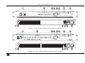
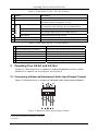
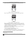
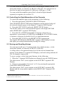
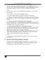
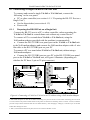
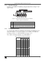
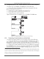
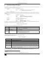
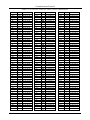
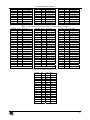
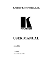
Kramer Electronics, Ltd.
USER MANUAL
Models:
VA-8xl, 8 Channel Balanced Stereo Audio Amplifier
VA-16xl, 16 Channel Balanced Stereo Audio Amplifier
Contents
Contents
1
2
3
4
5
Introduction
Getting Started
Overview
Your VA-8xl and VA-16xl
Operating Your VA-8xl and VA-16xl
1
1
2
2
4
5.1
5.2
5.3
Connecting a Balanced/Unbalanced Audio Input/Output Channel
Controlling the Gain/Attenuation of the Channels
Storing and Recalling Setups
4
6
6
6
Serial Control of the VA-8xl or VA-16xl
7
6.1
Controlling a Single VA-8xl or VA-16xl Unit
8
6.1.1
6.1.2
6.1.3
Preparing the RS-232 Port on a Single Unit
Dipswitch Settings
Setting the MACHINE #
8
9
9
6.2
Configuring up to a 240 Channel Balanced Stereo Audio Amplifier
10
6.2.1
7
Connecting a Control Interface on a Set of Units
Flash Memory Upgrade
10
13
7.1
7.2
7.3
Downloading from the Internet
Connecting the PC to the RS-232 Port
Upgrading Firmware
13
13
13
8
9
Technical Specifications
Communication Protocol
18
19
Figures
Figure 1: VA-8xl 8 Channel Balanced Stereo Audio Amplifier
Figure 2: VA-16xl 16 Channel Balanced Stereo Audio Amplifier
Figure 3: Balanced Audio Input/Output Channel
Figure 4: Unbalanced Audio Input Channel
Figure 5: Unbalanced Audio Output Channel
Figure 6: Connecting a VA-8xl or VA-16xl to a PC without using a Null-modem Adapter
Figure 7: Rear Panel Dipswitches (Factory Default)
Figure 8: Configuring up to 15 VA-8xl or VA-16xl Units
Figure 9: Preparing the RS-232 Connectors
Figure 10: An RS-485 Control Interface Setup
Figure 11: Splash Screen
Figure 12: Atmel – Flip Window
Figure 13: Open Configuration File Select Window
Figure 14: Atmel – Flip Window (RS-232 Communication)
Figure 15: RS-232 Window
Figure 16: Atmel – Flip Window (Connected)
Figure 17: Atmel – Flip Window (Operation Completed)
3
3
4
5
5
8
9
10
11
12
14
14
15
15
16
16
17
i
Contents
Tables
Table 1: Front Panel VA-8xl / VA-16xl Features
Table 2: Rear Panel VA-8xl / VA-16xl Features
Table 3: Dipswitch Definitions
Table 4: Machine # Dipswitch Settings
Table 5: Technical Specifications of the VA-8xl or VA-16xl
Table 6: Instruction Codes
Table 7: Examples
Table 8: VA-16xl Hex Codes for Gain Control (Attenuation)
Table 9: VA-16xl Hex Codes for Gain Control (Amplification)
Table 10: Channel Number Codes
ii
4
4
9
9
18
19
19
20
21
21
KRAMER: SIMPLE CREATIVE TECHNOLOGY
Introduction
1
Introduction
Welcome to Kramer Electronics (since 1981): a world of unique, creative and
affordable solutions to the infinite range of problems that confront the video,
audio and presentation professional on a daily basis. In recent years, we have
redesigned and upgraded most of our line, making the best even better! Our
350-plus different models now appear in 8 Groups1, which are clearly defined
by function.
Congratulations on purchasing your Kramer VA-8xl 8 Channel Balanced
Stereo Audio Amplifier and/or VA-16xl 16 Channel Balanced Stereo Audio
Amplifier, which are ideal for
• Duplication, production, or presentation systems requiring high quality
audio signal distribution
• Audio production and broadcast studios
The package includes the following items:
• VA-8xl 8 Channel Balanced Stereo Audio Amplifier or VA-16xl 16
Channel Balanced Stereo Audio Amplifier
• Power cord
• Null-modem adapter
• Windows®-based software
• This user manual2 and the Kramer concise product catalog/CD
2
Getting Started
We recommend that you:
• Unpack the equipment carefully and save the original box and packaging
materials for possible future shipment
• Review the contents of this user manual
• Use Kramer high performance high resolution cables3
1 GROUP 1: Distribution Amplifiers; GROUP 2: Video and Audio Switchers, Matrix Switchers and Controllers; GROUP 3:
Video, Audio, VGA/XGA Processors; GROUP 4: Interfaces and Sync Processors; GROUP 5: Twisted Pair Interfaces;
GROUP 6: Accessories and Rack Adapters; GROUP 7: Scan Converters and Scalers; and GROUP 8: Cables and Connectors
2 Download up-to-date Kramer user manuals from the Internet at this URL: http://www.kramerelectronics.com/manuals.html
3 The complete list of Kramer cables is on our Web site at http://www.kramerelectronics.com (click “Cables and Connectors”
in the Products section)
1
Overview
3
Overview
The high performance VA-8xl 8 Channel Balanced Stereo Audio Amplifier
and VA-16xl 16 Channel Balanced Stereo Audio Amplifier are designed for
professional and high-end consumer audio systems.
In particular, the VA-8xl and VA-16xl:
• Feature a digitally controlled volume control function, with gain from
-95dB (attenuation) up to +31dB (amplification) - in increments of 0.5dB
• Provide a clean, noise-free transition during gain setting changes
• With their outstanding audio specifications, ensure transparent
performance even in the most critical broadcast applications
• Have 8 and 16 channels respectively, each of which is independent
• Let you control the amplifier gain of the Left and Right channels—
together or separately—via the front panel buttons, or remotely via RS-232 or
RS-485
• Let you daisy-chain up to 15 machines in a single system using RS-485
or RS-232, allowing control of up to 240 stereo audio channels!
• Store and recall up to 15 configuration setups via the non-volatile
memory, using the front panel buttons, or remotely via RS-232 or RS-485
• Include a bright 7-segment LED display on the front panel, showing the
gain of the selected channel (that is, its left and right decibel status)
• Include easy-to-connect detachable terminal block connectors
• Are housed in a rugged, professional 1U rack mountable enclosure and
ship with Windows®-based software
Achieving the best performance means:
• Connecting only good quality connection cables, thus avoiding
interference, deterioration in signal quality due to poor matching, and elevated
noise levels (often associated with low quality cables)
• Avoiding interference from neighboring electrical appliances that may
adversely influence signal quality and positioning your Kramer VA-8xl or
VA-16xl in a location free from moisture and away from excessive sunlight
and dust
4
Your VA-8xl and VA-16xl
Figure 1 illustrates the VA-8xl 8 Channel Balanced Stereo Audio Amplifier
and Figure 2 illustrates the VA-16xl 16 Channel Balanced Stereo Audio
Amplifier. Table 1 defines the front panel of the VA-8xl and VA-16xl, and
Table 2 defines the rear panel of the VA-8xl and VA-16xl.
2
KRAMER: SIMPLE CREATIVE TECHNOLOGY
Your VA-8xl and VA-16xl
Figure 1: VA-8xl 8 Channel Balanced Stereo Audio Amplifier
Figure 2: VA-16xl 16 Channel Balanced Stereo Audio Amplifier
3
Operating Your VA-8xl and VA-16xl
Table 1: Front Panel VA-8xl / VA-16xl Features
#
1
2
Feature
POWER Switch
CHANNEL SELECTOR Buttons
Function(s)
Illuminated switch supplying power to the unit
(a). Select/deselect the stereo channel (from 1 to 8; or 1 to 16)
(b). Select a setup number (from 1 to 15)
1
DOWN Button
(a). Decreases the volume
(b). Stores the current setting in the non-volatile memory
LEFT Button
Selects/deselects the left channel
1
UP Button
(a). Increases the volume
(b). Recalls a setup from the non-volatile memory
RIGHT Button
Selects/deselects the right channel
2
LEFT/dB 7-segment LED Display
Shows the gain of the selected left channel
2
RIGHT/dB 7-segment LED Display Shows the gain of the selected right channel
LEVEL Control
3
4
5
6
7
8
Table 2: Rear Panel VA-8xl / VA-16xl Features
#
1
2
3
4
5
6
5
Feature
OUT Terminal Block Connectors
IN Terminal Block Connectors
RS-485 Detachable Terminal Block Port
RS-232 DB 9F Port
SETUP Dipswitches
Power Connector with FUSE
Function
Connect to audio acceptors (from 1 to 8; or 1 to 16)
Connect to audio sources (from 1 to 8; or 1 to 16)
Pin # 1 is for Ground; Pin # 2 is for +; Pin # 3 is for Connects to the PC or the Remote Controller
Dipswitches for setup of the unit
AC connector enabling power supply to the unit
Operating Your VA-8xl and VA-16xl
Section 5.1 describes how to connect a balanced/unbalanced stereo audio
channel. For control via a serial port, see section 6.
5.1 Connecting a Balanced/Unbalanced Audio Input/Output Channel
Figure 3 illustrates how to connect a balanced audio input/output channel:
Figure 3: Balanced Audio Input/Output Channel
1 In increments of 0.5dB from -95dB up to +31dB gain
2 In decibels
4
KRAMER: SIMPLE CREATIVE TECHNOLOGY
Operating Your VA-8xl and VA-16xl
Figure 4 illustrates how to connect an unbalanced audio input channel:
Figure 4: Unbalanced Audio Input Channel
Figure 5 illustrates how to connect an unbalanced audio output channel:
Figure 5: Unbalanced Audio Output Channel
When switching on the VA-8xl or VA-16xl (after a previous session), the
VA-8xl or VA-16xl briefly scan each channel1, showing the settings in the
7-segment LED Displays1. After that, the VA-8xl or VA-16xl go to channel
1, and show its gain/attenuation level in dB.
During regular work, the VA-8xl or VA-16xl show the status of the last
channel you observed and/or changed.
To observe the status of a Channel, do the following:
• Press a CHANNEL SELECTOR button.
That CHANNEL SELECTOR button illuminates2 and the decibel values of
the selected channel appear in the dimmed3 7-segment LED Displays1
1 Stored in the non-volatile memory
2 For about 20 seconds
3 When the LEDs are dimmed, you cannot change the gain or attenuation - the values are for observation only
5
Operating Your VA-8xl and VA-16xl
You can control the amplifier gain of the Left and Right channels via the
front panel buttons, or remotely via RS-232 or RS-485. You can increase or
decrease the gain in increments of 0.5dB from -95dB up to +31dB.
You can control the amplifier gain of the Left and/or Right channels
separately or together (see section 5.2).
5.2 Controlling the Gain/Attenuation of the Channels
To control the amplifier gain or the attenuation, do the following:
1. Press the appropriate CHANNEL SELECTOR button.
That CHANNEL SELECTOR button illuminates and the decibel values of
the selected channel appear in the dimmed1 7-segment LED Displays2.
2. Press the LEFT LEVEL and/or the RIGHT LEVEL button.
The decibel values of the selected channel appear in the bright LEFT/dB
and/or RIGHT/dB 7-segment LED Display.
3. Press the UP or DOWN button once to increase or decrease, as
appropriate, in increments of 0.5dB. Press and hold the UP or DOWN button,
to increase or decrease the decibel level by a significant amount.
4. Press the LEFT LEVEL or the RIGHT LEVEL button again.
The bright LEFT/dB and/or RIGHT/dB 7-segment LED Display becomes
dim again, preventing unintentionally altering the settings.
5.3 Storing and Recalling Setups
You can store/recall up to 15 settings in the non-volatile memory, via the
front panel buttons, or remotely via RS-232 or RS-485.
A setting refers to the gain/attenuation level of the selected channel that
appears in the dimmed 7-segment LED Displays, and each setting includes all
8 or 16 channels, respectively.
To store a setting, via the front panel buttons, do the following:
1. When the 7-segment LED Displays are dimmed, press the DOWN button.
The abbreviation “StO” (store) appears in the LEFT/dB 7-segment LED
Display.
2. Choose a setup number (between 1 to 15), by pressing the appropriate
CHANNEL SELECTOR button.
The abbreviation “StO” (store) appears in the LEFT/dB 7-segment LED
Display and the setup number appears in the RIGHT /dB 7-segment LED
Display.
1 When the LEDs are dimmed, you cannot change the gain or attenuation - the values are for observation only
2 Stored in the non-volatile memory
6
KRAMER: SIMPLE CREATIVE TECHNOLOGY
Serial Control of the VA-8xl or VA-16xl
3. Press the same CHANNEL SELECTOR button again.
The memory stores the chosen setup number. As confirmation, for a few
seconds, “YES” appears in the LEFT/dB 7-segment LED Display and the
setup number appears in the RIGHT /dB 7-segment LED Display.
Note:
• Saving a setup to an already allocated setup number, overwrites the
previous setup
• To cancel, press the LEFT or RIGHT button
To recall a setting, via the front panel buttons, do the following:
1. When the 7-segment LED Displays are dimmed, press the UP button.
The abbreviation “rCL” (recall) appears in the LEFT/dB 7-segment LED
Display.
2. Press the appropriate CHANNEL SELECTOR button.
The abbreviation “rCL” (recall) appears in the LEFT/dB 7-segment LED
Display and the number of that CHANNEL SELECTOR button appears in
the RIGHT /dB 7-segment LED Display.
3. Press the same CHANNEL SELECTOR button again.
The memory recalls the setup. As confirmation, for a few seconds, “YES”
appears in the LEFT/dB 7-segment LED Display and the setup number
appears in the RIGHT /dB 7-segment LED Display.
If no setting is stored in the non-volatile memory with that setup #, “NO”
appears in the LEFT/dB 7-segment LED Display and the setup number
appears in the RIGHT /dB 7-segment LED Display.
Note:
• Recalling a setup implements the amplifier gain or the attenuation
immediately
6
Serial Control of the VA-8xl or VA-16xl
You can control a single VA-8xl or VA-16xl unit (see section 6.1) or
configure up to a 240 channel balanced stereo audio amplifier, using 15
VA-16xl units via RS-485 or RS-232 (see section 6.2).
7
Serial Control of the VA-8xl or VA-16xl
6.1 Controlling a Single VA-8xl or VA-16xl Unit
To connect and control a single VA-8xl or VA-16xl unit, connect the
following1 to the rear panel:
• PC or other controller (see section 6.1.1: “Preparing the RS-232 Port on a
Single Unit”)
• Set the dipswitches (see section 6.1.2)
• Power cord
6.1.1
Preparing the RS-232 Port on a Single Unit
Connect the RS-232 port to a PC or other controller, unless operating the
VA-8xl or VA-16xl as a stand-alone unit without any control device2.
To connect a PC to a stand-alone VA-8xl or VA-16xl unit, using the
Null-modem adapter provided with the machine (recommended):
• Connect the RS-232 DB9 rear panel port on the VA-8xl or VA-16xl unit
to the Null-modem adapter and connect the Null-modem adapter with a 9 wire
flat cable to the RS-232 DB9 port on your PC
To connect a PC to a stand-alone VA-8xl or VA-16xl unit, without using a
Null-modem adapter:
• Connect the RS-232 DB9 port on your PC to the RS-232 DB9 rear panel
port on the VA-8xl or VA-16xl unit, as Figure 6 illustrates (depending on
whether the PC has a 9-pin or 25-pin connector)
Figure 6: Connecting a VA-8xl or VA-16xl to a PC without using a Null-modem Adapter
1 Switch OFF the power on each device before connecting it to your VA-8xl or VA-16xl. After connecting your VA-8xl or
VA-16xl, switch on its power and then switch on the power on each device. Switching on the VA-8xl or VA-16xl, recalls the
previous setup of all the channels from the non-volatile memory. After changing a setting(s), it can take up to 30 seconds
before these settings are saved
2 That is, with control from the front panel, and not via a remote controller or a PC
8
KRAMER: SIMPLE CREATIVE TECHNOLOGY
Serial Control of the VA-8xl or VA-16xl
6.1.2
Dipswitch Settings
Configure the VA-8xl or VA-16xl by setting the dipswitches as Figure 7 and
Table 3 define:
Figure 7: Rear Panel Dipswitches (Factory Default)
Table 3: Dipswitch Definitions
DIP #
1-4
5
6
7/8
6.1.3
Function:
Set the MACHINE # (see Table 4 in section 6.1.3)
Not used
RS-485 termination for first and last machine = ON (RS-485 line
terminates with 110Ω); for others = OFF (RS-485 line is open)
Used for the firmware upgrade procedure (see section 7)
Setting the MACHINE #
To control a unit via RS-232 or RS-485, each unit has to be identified via its
unique MACHINE #. Set the MACHINE # on a VA-8xl or VA-16xl unit
according to Table 4. A valid MACHINE # is from 1 to 15.
For a single, stand alone machine, set as MACHINE # 1.
Table 4: Machine # Dipswitch Settings
MACHINE #
DIPSWITCH
1
2
1
ON
OFF OFF OFF
2
OFF ON
OFF OFF
3
ON
OFF OFF
4
OFF OFF ON
5
ON
6
OFF ON
ON
OFF
7
ON
ON
OFF
8
OFF OFF OFF ON
9
10
ON OFF OFF ON
OFF ON OFF ON
ON
3
OFF ON
ON
ON
4
OFF
OFF
11
ON
12
OFF OFF ON
OFF ON
ON
13
ON
ON
14
OFF ON
ON
ON
15
ON
ON
ON
OFF ON
ON
9
Serial Control of the VA-8xl or VA-16xl
6.2 Configuring up to a 240 Channel Balanced Stereo Audio Amplifier
To connect up to 15 VA-8xl or VA-16xl units, do the following1:
• Connect the balanced/unbalanced audio sources/acceptors to the rear
panel on each unit (see section 5.1)
• Connect a PC or other controller (see section 6.2.1)
• Set the dipswitches on each unit (see section 6.1.2)
• Connect the power cord on each unit
Figure 8 illustrates how to configure up to 15 VA-8xl or VA-16xl units.
Figure 8: Configuring up to 15 VA-8xl or VA-16xl Units2
6.2.1
Connecting a Control Interface on a Set of Units
To connect the control interface on a set of units, do one of the following:
• Connect the RS-232 port on the first VA-8xl or VA-16xl unit to a PC or
other controller, and then connect the RS-232 port on each of the VA-8xl or
VA-16xl units, using the specially prepared RS-232 cable (see section 6.2.1.1); or
• Connect a PC or other controller to the “RS-232 in” DB9F port on a Kramer
Tools VP-43xl Interface Converter and connect the RS-485 port on the VP-43xl
to the RS-485 ports on each of the VA-8xl or VA-16xl units (see section 6.2.1.2)
1 Switch OFF the power on each device before connecting it to a VA-8xl or VA-16xl unit. After connecting all the VA-8xl or
VA-16xl units, switch on their power and then switch on the power on each device that connects to them. Switching on each
VA-8xl or VA-16xl unit, recalls the previous setup of each channel from the non-volatile memory. After changing a
setting(s), it can take up to 30 seconds before these settings are saved
2 See Figure 9 for details of how to interconnect the RS-232 ports
10
KRAMER: SIMPLE CREATIVE TECHNOLOGY
Serial Control of the VA-8xl or VA-16xl
6.2.1.1
Preparing the RS-232 Port1 on a Set of Units
To connect a PC to a set of VA-8xl or VA-16xl units, do not use a
null-modem adapter. Do the following2:
1. Prepare the RS-232 DB9F connector (A), by connecting PIN 4 to PIN 6
and connecting PINS 8, 7, and 1 together.
2. Attach the RS-232 DB9F connector (A) to another RS-232 DB9M
connector (B) by connecting PIN 5 to PIN 5, PIN 3 to PIN 2, and PIN 2 to
PIN 3.
3. Connect the RS-232 DB9F connector (A) to your PC’s RS-232 DB9M
port.
4. Attach the RS-232 DB9M connector (B) to another RS-232 DB9M
connector (C), by connecting PIN 5 to PIN 5, PIN 8 to PIN 3, PIN 9 to PIN 2.
5. Connect the RS-232 DB9M connector (B) to the RS-232 DB9F port on
the first VA-8xl or VA-16xl unit.
6. Attach the RS-232 DB9M connector (C) to another RS-232 DB9M
connector, if required, by connecting PIN 5 to PIN 5, PIN 8 to PIN 3, PIN 9 to
PIN 2.
7. Connect the RS-232 DB9M connector (C) to the RS-232 DB9F port on
the next VA-8xl or VA-16xl unit.
Figure 9: Preparing the RS-232 Connectors
1 Choose the RS-232 control interface, for a range of about 25 meters used for a point-to-point connection
2 By preparing a special RS-232 cable (not required when connecting a stand-alone VA-8xl or VA-16xl unit (see section
6.1.1)), as illustrated in Figure 8 and Figure 9
11
Serial Control of the VA-8xl or VA-16xl
6.2.1.2
Connecting the RS-485 Control Interface1
To connect an RS-485 connector on one VA-8xl or VA-16xl unit to an
RS-485 connector on another unit:
1. Connect the “+” PIN on the first VA-8xl or VA-16xl unit to the “+” PIN
on the second VA-8xl or VA-16xl unit
2. Connect the “-” PIN on the first VA-8xl or VA-16xl unit to the “-” PIN
on the second VA-8xl or VA-16xl unit
3. If shielded cable is used for an RS-485 connection, connect the shield to
the Ground PIN.
Figure 10 illustrates the RS-485 line that connects:
• Between each VA-8xl / VA-16xl unit
• To the PC via a Kramer Tools VP-43xl Interface Converter (connect the
PC’s DB 9 COM port to the “RS-232 in” DB9F port on the VP-43xl. Next,
connect the RS-485 port on the VP-43xl to the RS-485 ports on the VA-8xl or
VA-16xl units)
Figure 10: An RS-485 Control Interface Setup
1 Choose the RS-485 control interface, to operate the VA-8xl or VA-16xl from an extended distance of up to 1200 meters
12
KRAMER: SIMPLE CREATIVE TECHNOLOGY
Flash Memory Upgrade
7
Flash Memory Upgrade
The VA-8xl or VA-16xl firmware is located in FLASH memory, which lets
you upgrade to the latest Kramer firmware version in minutes! The process
involves:
• Downloading from the Internet (see section 7.1)
• Connecting the PC to the RS-232 port (see section 7.2)
• Upgrading Firmware (see section 7.3)
7.1 Downloading from the Internet
You can download the up-to-date file from the Internet. To do so:
1. Go to our Web site at http://www.kramerelectronics.com and download
the file: “FLIP_VA16xl.zip” from the Technical Support section.
2. Extract the file: “FLIP_VA16xl.zip” to a folder (for example, C:\Program
Files\Kramer Flash).
7.2 Connecting the PC to the RS-232 Port
Before installing the latest Kramer firmware version on a VA-8xl or VA-16xl
unit, do the following:
1. Connect the RS-232 DB9 rear panel port on the VA-8xl or VA-16xl unit
to the Null-modem adapter and connect the Null-modem adapter with a 9
wire flat cable to the RS-232 DB9 COM port on your PC (see section 6.1.1).
It is recommended that you use COM port1 2. However, if your computer has
only one COM port, open the file: “Va16xl.cfg” (located at C:\Program
Files\Kramer Flash\Va16xl.cfg) in Notepad, and change “set port COM2” to
“set port COM1”.
2. Set the dipswitches as follows:
• Set DIP 8 ON
• Set DIP 7 ON
3. Connect the power cord and turn the POWER switch on the VA-8xl or
VA-16xl ON.
The 7-segment LED Displays may show erratic data, which should be ignored.
7.3 Upgrading Firmware
Follow these steps to upgrade the firmware:
1. Double click the desktop icon: “Shortcut to FLIP.EXE”.
The Splash screen appears as follows:
1 The software is preset for use with COM port 2
13
Flash Memory Upgrade
Figure 11: Splash Screen
2. After a few seconds, the Splash screen is replaced by the “Atmel – Flip”
window:
Figure 12: Atmel – Flip Window
3. Press the keyboard shortcut key F4 (or select the “Read Configuration
File” command from the File menu, or press the keys: Alt FR).
The “Open Configuration File” window appears:
14
KRAMER: SIMPLE CREATIVE TECHNOLOGY
Flash Memory Upgrade
Figure 13: Open Configuration File Select Window
4. Choose the file: “Va16xl.cfg” (by double-clicking it).
If COM 2 was not selected (see section 7.2), an RS-232 error message
appears. In the “Atmel – Flip” window, the Operations Flow column is
disabled, and crosses appear in the third column.
Figure 14: Atmel – Flip Window (RS-232 Communication)
5. Click OK and press the keyboard shortcut key F3 (or select the
“Communication / RS232” command from the Settings menu, or press the
keys: Alt SCR).
The “RS232” window appears. Change the COM port:
15
Flash Memory Upgrade
Figure 15: RS-232 Window
6. Click Connect.
In the “Atmel – Flip” window, in the Operations Flow column, the Run
button is active, and the name of the chip appears as the name of the third
column: T89C51RD2.
Verify that in the Buffer Information column, the “HEX File: Va16xl.hex”
appears.
Figure 16: Atmel – Flip Window (Connected)
7. Click Run.
After each stage in the operation is completed, the check-box for that stage
becomes colored green1.
When the operation is completed, all 4 check-boxes will be colored green and
the status bar message: Memory Verify Pass appears2:
1 See also the blue progress indicator on the status bar
2 If an error message: “Not Finished” shows, click Run again
16
KRAMER: SIMPLE CREATIVE TECHNOLOGY
Flash Memory Upgrade
Figure 17: Atmel – Flip Window (Operation Completed)
8. Close the “Atmel – Flip” window.
9. Turn the POWER switch on the VA-8xl or VA-16xl OFF.
10. Disconnect the RS-232 DB9 rear panel port on the VA-8xl or VA-16xl
unit from the Null-modem adapter.
11. Set DIP 7 OFF.
12. Set DIP 8 OFF.
13. Turn the POWER switch on the VA-8xl or VA-16xl ON.
Upon initialization, the new VA-8xl or VA-16xl software version shows in
the RIGHT/dB 7-segment LED Display.
17
Technical Specifications
8
Technical Specifications
Table 5 includes the technical specifications:
1
Table 5: Technical Specifications of the VA-8xl or VA-16xl
INPUTS:
VA-8xl: 8 balanced stereo audio +4dBm / 30kΩ on detachable terminal blocks
VA-16xl: 16 balanced stereo audio +4dBm / 30kΩ on detachable terminal blocks
OUTPUTS:
VA-8xl: 8 balanced stereo audio +4dBm / 50Ω on detachable terminal blocks
VA-16xl: 16 balanced stereo audio +4dBm / 50Ω on detachable terminal blocks
-95dB to +31dB
>20dBu balanced (TND +N <0.01)
20 Hz to 40 kHz
<90dB (GAIN 0dB)
0.006%, +4dBu 1kHz
Front pushbuttons, RS-232, and RS-485
Gain in dB for left and right channels
90 - 240V 13VA
19-inch (W), 7-inch (D) 1U (H) rack-mountable
3.5 kg (7.8 lbs.) approx.
Power cord, Null modem adapter, Windows®-based control software
GAIN:
MAX. OUTPUT LEVEL:
BANDWIDTH (-0.3dB):
NOISE FLOOR:
THD + NOISE:
CONTROLS:
INDICATORS:
POWER SOURCE:
DIMENSIONS:
WEIGHT:
ACCESSORIES:
1 Specifications are subject to change without notice
18
KRAMER: SIMPLE CREATIVE TECHNOLOGY
Communication Protocol
Communication Protocol1
9
2
The VA-8xl or VA-16xl is compatible with Kramer’s Protocol 2000 (version 0.43). This RS-232 / RS-485 communication
protocol uses four bytes of information as defined below.
1st BYTE:
Bit 7 (MSB) - Defined as 0.
Bit 6
0 - for sending information to the switchers (from the PC);
1 - for sending to the PC (from the switcher).
Bits 5…0 – “INSTRUCTION”
The function that is to be performed by the switcher(s) is defined by the INSTRUCTION (see Table 6 below). Similarly, if a
function is performed via the machine’s front panel, then these bits are set according to the INSTRUCTION NO., which was
performed.
2nd BYTE:
Bit 7 (MSB)
Bits 4…0
Bit 5
Bit 6
- Defined as 1.
- Channel number
- Left (set to 1 when referring to the left channel)
- Right (set to 1 when referring to the right channel)
3rd BYTE:
Bit 7 (MSB) - Defined as 1.
Bits 6…0 – 7 least significant bits of data
4th BYTE:
Bit 7 (MSB) - Defined as 1.
Bit 5
- MSB of data (7 LSBs are in 3rd byte).
Bits 4…0
- MACHINE NUMBER.
For RS-232, a null-modem connection between the machine and controller is used. For both RS-232/RS-485 interfaces the
default data rate is 9600 baud, with no parity, 8 data bits and 1 stop bit.
Table 6: Instruction Codes
Note: All values in the table are decimal, unless otherwise stated.
#
DESCRIPTION
3rd BYTE
22dec
(16hex)
SET AUDIO GAIN
Set 7 LSBs of gain value
Gain (dB) = 31.5 – (0.5x(255-DATA))
24dec
(18hex)
INCREASE / DECREASE
AUDIO GAIN
0 - increase gain
1 - decrease gain
25dec
(19hex)
REQUEST AUDIO GAIN
As in Instruction 22dec above.
When requesting both channels, the reply is:
For equal left and right gain: bits 5 = bit 6
For unequal left and right gain: bits 6 = 0; bit 5 = 1 for reply for left channel
In addition to the above, instructions 15, 18, 19, 20, 61, 62 (decimal) of Kramer’s Protocol 2000 are also fully implemented in
the unit. For instructions 18 and 19, setups 01 to 15 (decimal) are valid.
See the examples in the Table 7 below:
Table 7: Examples
COMMAND
EXAMPLES (MACHINE # 1)
16h E7h 90h 81h
Set channel 7 both left and right gain -88dB
16h AAh FFh 81h
Set channel 10 left gain -32.5dB
16h CAh COh A1h
Set channel 10 right gain 0dB
16h FOh DOh A1h
Set channel 16 both left and right gain +8dB
18h EFh 80h 81h
Increment (increase) gain on 0.5dB on left and right of Channel 15
19h CFh 80h 81h
Request gain of Channel 15 right.
If the gain is 0dB for both left and right channels, then the reply would be: 59h EFh COh A1h
19h EEh 80h 81h
Request gain of Channel 14 both left and right.
If the gain is different for the left and right channels, then, for +3dB gain in the left channel the
reply would be: 59h AEh C6h A1h
Table 8 on page 20 defines the VA-16xl Hex Codes for Gain Control (Attenuation), Table 9 on page 21 defines the VA-16xl
Hex Codes for Gain Control (Amplification), and Table 10 on page 21 defines the Channel Number Codes.
1 VER-0.1
2 See the Technical Support section of our Web site: http://www.kramerelectronics.com
19
Communication Protocol
Table 8: VA-16xl Hex Codes for Gain Control (Attenuation)
Gain (dB)
Mute
-95.5
-95
-94.5
-94
-93.5
-93
-92.5
-92
-91.5
-91
-90.5
-90
-89.5
-89
-88.5
-88
-87.5
-87
-86.5
-86
-85.5
-85
-84.5
-84
-83.5
-83
-82.5
-82
-81.5
-81
-80.5
-80
-79.5
-79
-78.5
-78
-77.5
-77
-76.5
-76
-75.5
-75
-74.5
-74
-73.5
-73
-72.5
-72
-71.5
-71
-70.5
-70
-69.5
-69
-68.5
20
LED
---95.5
-95
-94.5
-94
-93.5
-93
-92.5
-92
-91.5
-91
-90.5
-90
-89.5
-89
-88.5
-88
-87.5
-87
-86.5
-86
-85.5
-85
-84.5
-84
-83.5
-83
-82.5
-82
-81.5
-81
-80.5
-80
-79.5
-79
-78.5
-78
-77.5
-77
-76.5
-76
-75.5
-75
-74.5
-74
-73.5
-73
-72.5
-72
-71.5
-71
-70.5
-70
-69.5
-69
-68.5
Hex Codes
16
16
16
16
16
16
16
16
16
16
16
16
16
16
16
16
16
16
16
16
16
16
16
16
16
16
16
16
16
16
16
16
16
16
16
16
16
16
16
16
16
16
16
16
16
16
16
16
16
16
16
16
16
16
16
16
XX
XX
XX
XX
XX
XX
XX
XX
XX
XX
XX
XX
XX
XX
XX
XX
XX
XX
XX
XX
XX
XX
XX
XX
XX
XX
XX
XX
XX
XX
XX
XX
XX
XX
XX
XX
XX
XX
XX
XX
XX
XX
XX
XX
XX
XX
XX
XX
XX
XX
XX
XX
XX
XX
XX
XX
80 81
81 81
82 81
83 81
84 81
85 81
86 81
87 81
88 81
89 81
8A 81
8B 81
8C 81
8D 81
8E 81
8F 81
90 81
91 81
92 81
93 81
94 81
95 81
96 81
97 81
98 81
99 81
9A 81
9B 81
9C 81
9D 81
9E 81
9F 81
A0 81
A1 81
A2 81
A3 81
A4 81
A5 81
A6 81
A7 81
A8 81
A9 81
AA 81
AB 81
AC 81
AD 81
AE 81
AF 81
B0 81
B1 81
B2 81
B3 81
B4 81
B5 81
B6 81
B7 81
Gain (dB)
-68
-67.5
-67
-66.5
-66
-65.5
-65
-64.5
-64
-63.5
-63
-62.5
-62
-61.5
-61
-60.5
-60
-59.5
-59
-58.5
-58
-57.5
-57
-56.5
-56
-55.5
-55
-54.5
-54
-53.5
-53
-52.5
-52
-51.5
-51
-50.5
-50
-49.5
-49
-48.5
-48
-47.5
-47
-46.5
-46
-45.5
-45
-44.5
-44
-43.5
-43
-42.5
-42
-41.5
-41
-40.5
LED
-68
67.
-67
66.
-66
65.
-65
64.
-64
63.
-63
62.
-62
61.
-61
60.
-60
59.
-59
58.
-58
57.
-57
56.
-56
55.
-55
54.
-54
53.
-53
52.
-52
51.
-51
50.
-50
49.
-49
48.
-48
47.
-47
46.
-46
45.
-45
44.
-44
43.
-43
42.
-42
41.
-41
40.
Hex Codes
16
16
16
16
16
16
16
16
16
16
16
16
16
16
16
16
16
16
16
16
16
16
16
16
16
16
16
16
16
16
16
16
16
16
16
16
16
16
16
16
16
16
16
16
16
16
16
16
16
16
16
16
16
16
16
16
XX
XX
XX
XX
XX
XX
XX
XX
XX
XX
XX
XX
XX
XX
XX
XX
XX
XX
XX
XX
XX
XX
XX
XX
XX
XX
XX
XX
XX
XX
XX
XX
XX
XX
XX
XX
XX
XX
XX
XX
XX
XX
XX
XX
XX
XX
XX
XX
XX
XX
XX
XX
XX
XX
XX
XX
Gain (dB)
B8 81
B9 81
BA 81
BB 81
BC 81
BD 81
BE 81
BF 81
C0 81
C1 81
C2 81
C3 81
C4 81
C5 81
C6 81
C7 81
C8 81
C9 81
CA 81
CB 81
CC 81
CD 81
CE 81
CF 81
D0 81
D1 81
D2 81
D3 81
D4 81
D5 81
D6 81
D7 81
D8 81
D9 81
DA 81
DB 81
DC 81
DD 81
DE 81
DF 81
E0 81
E1 81
E2 81
E3 81
E4 81
E5 81
E6 81
E7 81
E8 81
E9 81
EA 81
EB 81
EC 81
ED 81
EE 81
EF 81
-40
-39.5
-39
-38.5
-38
-37.5
-37
-36.5
-36
-35.5
-35
-34.5
-34
-33.5
-33
-32.5
-32
-31.5
-31
-30.5
-30
-29.5
-29
-28.5
-28
-27.5
-27
-26.5
-26
-25.5
-25
-24.5
-24
-23.5
-23
-22.5
-22
-21.5
-21
-20.5
-20
-19.5
-19
-18.5
-18
-17.5
-17
-16.5
-16
15.5
-15
-14.5
-14
-13.5
-13
-12.5
LED
-40
-39.5
-39
-38.5
-38
-37.5
-37
-36.5
-36
-35.5
-35
-34.5
-34
-33.5
-33
-32.5
-32
-31.5
-31
-30.5
-30
-29.5
-29
-28.5
-28
-27.5
-27
-26.5
-26
-25.5
-25
-24.5
-24
-23.5
-23
-22.5
-22
-21.5
-21
-20.5
-20
-19.5
-19
-18.5
-18
-17.5
-17
-16.5
-16
-15.5
-15
-14.5
-14
-13.5
-13
-12.5
Hex Codes
16
16
16
16
16
16
16
16
16
16
16
16
16
16
16
16
16
16
16
16
16
16
16
16
16
16
16
16
16
16
16
16
16
16
16
16
16
16
16
16
16
16
16
16
16
16
16
16
16
16
16
16
16
16
16
16
XX
XX
XX
XX
XX
XX
XX
XX
XX
XX
XX
XX
XX
XX
XX
XX
XX
XX
XX
XX
XX
XX
XX
XX
XX
XX
XX
XX
XX
XX
XX
XX
XX
XX
XX
XX
XX
XX
XX
XX
XX
XX
XX
XX
XX
XX
XX
XX
XX
XX
XX
XX
XX
XX
XX
XX
F0 81
F1 81
F2 81
F3 81
F4 81
F5 81
F6 81
F7 81
F8 81
F9 81
FA 81
FB 81
FC 81
FD 81
FE 81
FF 81
80 A1
81 A1
82 A1
83 A1
84 A1
85 A1
86 A1
87 A1
88 A1
89 A1
8A A1
8B A1
8C A1
8D A1
8E A1
8F A1
90 A1
91 A1
92 A1
93 A1
94 A1
95 A1
96 A1
97 A1
98 A1
99 A1
9A A1
9B A1
9C A1
9D A1
9E A1
9F A1
A0 A1
A1 A1
A2 A1
A3 A1
A4 A1
A5 A1
A6 A1
A7 A1
KRAMER: SIMPLE CREATIVE TECHNOLOGY
Communication Protocol
Gain (dB)
-12
-11.5
-11
-10.5
-10
-9.5
-9
-8.5
LED
Hex Codes
-12
-11.5
-11
-10.5
-10
-9.5
-9
-8.5
16
16
16
16
16
16
16
16
XX
XX
XX
XX
XX
XX
XX
XX
A8 A1
A9 A1
AA A1
AB A1
AC A1
AD A1
AE A1
AF A1
Gain (dB)
-8
-7.5
-7
-6.5
-6
-5.5
-5
-4.5
LED
-8
-7.5
-7
-6.5
-6
-5.5
-5
-4.5
Hex Codes
16
16
16
16
16
16
16
16
XX
XX
XX
XX
XX
XX
XX
XX
B0
B1
B2
B3
B4
B5
B6
B7
Gain (dB)
A1
A1
A1
A1
A1
A1
A1
A1
-4
-3.5
-3
-2.5
-2
-1.5
-1
-0.5
LED
-4
-3.5
-3
-2.5
-2
-1.5
-1
-0.5
Hex Codes
16
16
16
16
16
16
16
16
XX
XX
XX
XX
XX
XX
XX
XX
B8 A1
B9 A1
BA A1
BB A1
BC A1
BD A1
BE A1
BF A1
Table 9: VA-16xl Hex Codes for Gain Control (Amplification)
Gain (dB)
0
+0.5
+1
+1.5
+2
+2.5
+3
+3.5
+4
+4.5
+5
+5.5
+6
+6.5
+7
+7.5
+8
+8.5
+9
+9.5
+10
LED
0
+0.5
+1
+1.5
+2
+2.5
+3
+3.5
+4
+4.5
+5
+5.5
+6
+6.5
+7
+7.5
+8
+8.5
+9
+9.5
+10
Hex Codes
16
16
16
16
16
16
16
16
16
16
16
16
16
16
16
16
16
16
16
16
16
XX
XX
XX
XX
XX
XX
XX
XX
XX
XX
XX
XX
XX
XX
XX
XX
XX
XX
XX
XX
XX
C0 A1
C1 A1
C2 A1
C3 A1
C4 A1
C5 A1
C6 A1
C7 A1
C8 A1
C9 A1
CA A1
CB A1
CC A1
CD A1
CE A1
CF A1
D0 A1
D1 A1
D2 A1
D3 A1
D4 A1
Gain (dB)
+10.5
+11
+11.5
+12
+12.5
+13
+13.5
+14
+14.5
+15
+15.5
+16
+16.5
+17
+17.5
+18
+18.5
+19
+19.5
+20
+20.5
LED
+10.5
+11
+11.5
+12
+12.5
+13
+13.5
+14
+14.5
+15
+15.5
+16
+16.5
+17
+17.5
+18
+18.5
+19
+19.5
+20
+20.5
Hex Codes
16 XX
16 XX
16 XX
16 XX
16 XX
16 XX
16 XX
16 XX
A1 XX
16
A1 XX
16
16
16
16
16
16
16
16
16
16
16
16
XX
XX
XX
XX
XX
XX
XX
XX
XX
XX
XX
D5 A1
D6 A1
D7 A1
D8 A1
D9 A1
DA A1
DB A1
DC
DD
DE A1
DF A1
E0 A1
E1 A1
E2 A1
E3 A1
E4 A1
E5 A1
E6 A1
E7 A1
E8 A1
E9 A1
Gain (dB)
+21
+21.5
+22
+22.5
+23
+23.5
+24
+24.5
+25
+25.5
+26
+26.5
+27
+27.5
+28
+28.5
+29
+29.5
+30
+30.5
+31
+31.5
LED
+21
+21.5
+22
+22.5
+23
+23.5
+24
+24.5
+25
+25.5
+26
+26.5
+27
+27.5
+28
+28.5
+29
+29.5
+30
+30.5
+31
+31.5
Hex Codes
16
16
16
16
16
16
16
16
16
16
16
16
16
16
16
16
16
16
16
16
16
16
XX
XX
XX
XX
XX
XX
XX
XX
XX
XX
XX
XX
XX
XX
XX
XX
XX
XX
XX
XX
XX
XX
EA A1
EB A1
EC A1
ED A1
EE A1
EF A1
F0 A1
F1 A1
F2 A1
F3 A1
F4 A1
F5 A1
F6 A1
F7 A1
F8 A1
F9 A1
FA A1
FB A1
FC A1
FD A1
FE A1
FF A1
Table 10: Channel Number Codes
Channel
1
2
3
4
5
6
7
8
9
10
11
12
13
14
15
16
Left
Right
A1
A2
A3
A4
A5
A6
A7
A8
A9
AA
AB
AC
AD
AE
AF
B0
C1
C2
C3
C4
C5
C6
C7
C8
C9
CA
CB
CC
CD
CE
CF
D0
Both
(L and R)
E1
E2
E3
E4
E5
E6
E7
E8
E9
EA
EB
EC
ED
EE
EF
F0
21
LIMITED WARRANTY
Kramer Electronics (hereafter Kramer) warrants this product free from defects in material and workmanship under the
following terms.
HOW LONG IS THE WARRANTY
Labor and parts are warranted for three years from the date of the first customer purchase.
WHO IS PROTECTED?
Only the first purchase customer may enforce this warranty.
WHAT IS COVERED AND WHAT IS NOT COVERED
Except as below, this warranty covers all defects in material or workmanship in this product. The following are not covered by
the warranty:
1.
Any product which is not distributed by Kramer, or which is not purchased from an authorized Kramer dealer. If you are
uncertain as to whether a dealer is authorized, please contact Kramer at one of the agents listed in the web site
www.kramerelectronics.com.
Any product, on which the serial number has been defaced, modified or removed.
Damage, deterioration or malfunction resulting from:
i)
Accident, misuse, abuse, neglect, fire, water, lightning or other acts of nature
ii)
Product modification, or failure to follow instructions supplied with the product
iii)
Repair or attempted repair by anyone not authorized by Kramer
iv)
Any shipment of the product (claims must be presented to the carrier)
v)
Removal or installation of the product
vi)
Any other cause, which does not relate to a product defect
vii)
Cartons, equipment enclosures, cables or accessories used in conjunction with the product
2.
3.
WHAT WE WILL PAY FOR AND WHAT WE WILL NOT PAY FOR
We will pay labor and material expenses for covered items. We will not pay for the following:
1.
2.
Removal or installations charges.
Costs of initial technical adjustments (set-up), including adjustment of user controls or programming. These costs are the
responsibility of the Kramer dealer from whom the product was purchased.
Shipping charges.
3.
HOW YOU CAN GET WARRANTY SERVICE
1.
2.
To obtain service on you product, you must take or ship it prepaid to any authorized Kramer service center.
Whenever warranty service is required, the original dated invoice (or a copy) must be presented as proof of warranty coverage,
and should be included in any shipment of the product. Please also include in any mailing a contact name, company, address, and
a description of the problem(s).
For the name of the nearest Kramer authorized service center, consult your authorized dealer.
3.
LIMITATION OF IMPLIED WARRANTIES
All implied warranties, including warranties of merchantability and fitness for a particular purpose, are limited in duration to
the length of this warranty.
EXCLUSION OF DAMAGES
The liability of Kramer for any effective products is limited to the repair or replacement of the product at our option. Kramer
shall not be liable for:
1.
Damage to other property caused by defects in this product, damages based upon inconvenience, loss of use of the product, loss
of time, commercial loss; or:
Any other damages, whether incidental, consequential or otherwise. Some countries may not allow limitations on how long an
implied warranty lasts and/or do not allow the exclusion or limitation of incidental or consequential damages, so the above
limitations and exclusions may not apply to you.
2.
This warranty gives you specific legal rights, and you may also have other rights, which vary from place to place.
NOTE: All products returned to Kramer for service must have prior approval. This may be obtained from your dealer.
This equipment has been tested to determine compliance with the requirements of:
EN-50081:
"Electromagnetic compatibility (EMC);
generic emission standard.
Part 1: Residential, commercial and light industry"
EN-50082:
"Electromagnetic compatibility (EMC) generic immunity standard.
Part 1: Residential, commercial and light industry environment".
CFR-47:
FCC Rules and Regulations:
Part 15: “Radio frequency devices
Subpart B – Unintentional radiators”
CAUTION!
⌦ Servicing the machines can only be done by an authorized Kramer technician. Any user who makes changes or modifications to
the unit without the expressed approval of the manufacturer will void user authority to operate the equipment.
⌦ Use the supplied DC power supply to feed power to the machine.
⌦ Please use recommended interconnection cables to connect the machine to other components.
22
KRAMER: SIMPLE CREATIVE TECHNOLOGY
For the latest information on our products and a list of Kramer
distributors, visit our Web site: www.kramerelectronics.com.
Updates to this user manual may be found at
http://www.kramerelectronics.com/manuals.html.
We welcome your questions, comments and feedback.
Kramer Electronics, Ltd.
Web site: www.kramerelectronics.com
E-mail: [email protected]
P/N: 2900-000816 REV 1