1
Page 7
3P6 M2 MAINTENANCE PLAN
Plan Document
2.
17 - 08 - 2005
Doc. 3P6-PLA-ESO-60100-0001
M2 OVERVIEW
2.1. History
Since ever the 3.6 telescope f/8 secondary unit has suffered from considerable
mechanical instabilities. This together with the inability to introduce online corrections
to the decentring comma has severely limited the optical performance of the telescope.
Considering that the new generation of instruments (e.g. HARPS) need to exploit the
maximum possible optical image quality attainable with the telescope, a new
mechanical design based on the NTT secondary unit concept was designed and built.
The new M2 unit is equipped with VLT complaint computer controlled servo drives for
the focus, X and Y motions of the secondary mirror unit.
The unit was commissioned during September/August 2004 and is successfully
operating since them. This zero failure 1 year period was the base criteria for defining
the frequency of the various maintenance tasks.
2.2. System
The motion control electronic components used for the M2 are:
¾ MACC4/INC [AP4] and VME-4SA [AP1] VME VLT standard modules.
¾ Harmonic Drive AC-Servo Amplifier SC500/510 [AP5]
Three Harmonic Drive Systems servo actuators type FHA-25B-3015E-E150 are used
for rotating the focus, X and Y driving screws. These actuators integrate a brushless
AC motor together with a harmonic reduction gear and an incremental 1500 PPR
optical shaft encoder coupled to the motor axis. Each linear drive is complemented by
end of stroke high precision limit/init switches together with coarse catastrophic-limit
switches.
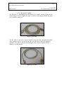
Every actuator is accompanied by three screw terminals group. All the connections
from the actuator and limit/init switches are routed trough these terminals to the control
LCU-power amplifiers cabinet. The signal groups correspond to; AC motor drive,
incremental encoder and limit/init switches.
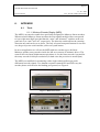
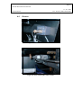
The control electronics is mounted on top of the M2 unit inside a hermetically sealed
Knürr cabinet equipped with an active heat exchanger unit. The cabinet houses a VME
LCU, three AC servo amplifiers and support circuitry.
Externally the control cabinet receives only; the mains 220VAC power supply, the
Ethernet connection, one inlet and one outlet coolant hoses. By opening the rear door
an external PC could be connected via RS232 to each AC servo amplifier and to the
LCU console port. This is for setup and engineering monitoring and maintenance of the
servo amplifiers and VME CPU configuration.
From the control cabinet three identical groups of signals are routed to its close
neighbour the M2 drive.