1
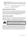
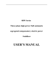
B2800XP Flow Monitor
Simplified Explosion-Proof Version
- For Liquid Meters -
PROGRAMMING & INSTALLATION
MANUAL
8635 Washington Avenue
Racine, Wisconsin 53406
Toll Free: 800.235.1638
Phone: 262.639.6770 • Fax: 262.417.1155
www.blancett.com
TABLE OF CONTENTS
Introduction ................................................................................................3
Specifications..............................................................................................4
Installation ...................................................................................................5
Operating the Monitor ...........................................................................8
Programming Mode ................................................................................8
Programming ......................................................................................8
K-factor ...................................................................................................9
Totalizer...............................................................................................11
Password .............................................................................................11
Additional Input Options ...................................................................12
Battery Replacement ...........................................................................12
Maintenance.............................................................................................14
Additional Scaling Parameters........................................................15
Programming Menu .............................................................................17
4-20 mA Output Programming Menu ..........................................18
Troubleshooting .....................................................................................19
Dimensions ...............................................................................................20
Part Number Information ..................................................................21
Replacement Parts ................................................................................21
Statement of Warranty ........................................................................22
NOTE: Blancett reserves the right to make any changes or improvements
to the product described in this manual at any time without notice.
2
Form No. B280-012 10/10
INTRODUCTION
The B2800 Flow Monitor is a state-of-the-art, digital signal processing flow
monitor designed to provide the user with exceptional flexibility at a very
affordable price. Though designed for use with Blancett flow meters, this
display can be used with almost any flow meter producing a low amplitude
AC output or contact closure signal(s).
The B2800 Flow Monitor is capable of accepting a low-level frequency
input for calculating flow rate and total. These calculations can then be
displayed in the desired units of measurement. All B2800 Flow Monitors
come pre-calibrated from the factory, if ordered with a Blancett flow meter.
If required, however, it can easily be re-configured in the field. The monitor’s
large 8 digit by .50” numeric liquid crystal display makes extended range
viewing practical. The second 8 digit by .25” alphanumeric display provides
for selectable units viewing in run mode and prompts for variables in
program mode. Finally, the user can choose between displaying rate, total
or alternating between both rate and total.
MENU
ENTER
Programming
Buttons
FIGURE 1
B2800XP Flow Monitor
Form No. B280-012 10/10
3
SPECIFICATIONS
Power Supply Options:
Battery Powered: 1 “D” size, 1.5 Volt alkaline battery
Loop Powered: 4-20 mA loop power
Power Consumption:
Battery Powered: Less than 1 mA @ 1.5 Vdc
Loop Powered: 25 mA (maximum)
Alphanumeric Rate and Total Display:
8 digit, .5” high numeric display
8 character, .25” high alphanumeric display
Pulsed Output Signal:
Outputs one pulse for each increment of the least significant totalizer digit
Max Voltage: 30 Vdc
Pulse Type: Opto-Isolated open collector transistor
Pulse Width ON State: 20 mS / max pulse rate 20 Hz
Current (ON State): 0.9 V drop @ 5.0 mA or 0.7 V drop @ 0.1 A
Magnetic Pick-up Inputs:
Frequency Range: 0 to 3500 Hz
Trigger Sensitivity: 30 mV p-p
Over Voltage Protected: ±30 Vdc
Frequency Measurement Accuracy: ±0.1%
Temperature Drift: 50 ppm / °C (max)
Optional Analog Output (Loop Powered Version):
4-20 mA Current Loop
Resolution: 1:4000
Transient Over Voltages: Category 3, in accordance with IEC664
Pollution Degree: 2, in accordance with IEC664
Mounting Classification: NEMA/UL/CSA Type 4 (IP66)
Environmental:
Operating Temperature: -22 °F to +158 °F (-30 °C to +70 °C)
Humidity: 0-90% Non-condensing
Certifications:
CSA Ordinary Locations:
To- C22.2 No. 1010-1 for Canada
ISA S82.02 for US
CSA Hazardous Locations:
For- Class I, Div 1 Groups B,C, D
Class II, Div 1 Groups E, F, G
Class III; Type 4X; T6 @ 70 °F
To- C22.2 No. 30 for Canada
FM3615 for US
4
Form No. B280-012 10/10
EXPLOSION-PROOF ENCLOSURE
The EIH Instrument Enclosure is designed to house instrumentation and
control equipment as well as act as a conduit outlet body in hazardous,
abusive and wet locations.
The EIH enclosure is approved by Underwriters Laboratories Inc., Canadian
Standards Association, Factory Mutual and CENELEC for use in Class I,
Groups B*, C**, and D; Class II, Groups E, F, and G; and Class II hazardous
(classified) locations as defined by the National Electrical Code® and
Canadian Electrical Code. It is also NEMA/UL/CSA Type 4 and IP66 rated for
watertight applications.
* With conduit seals installed within 18 inches of enclosure.
** Unsealed conduit lengths must not exceed 5 ft. (152 cm).
INSTALLATION
WARNING: Electrical power must be “OFF” before and
during installation and maintenance.
1. EIH Instrument Enclosures are furnished with ¾” NPT offset throughfeed cast hubs for conduit entries. (Use Cooper Crouse-Hinds RE21-SA
to reduce to ½” hubs.)
2. Secure the enclosure to the conduit system. If the enclosure has
mounting feet, select a mounting location that will provide sufficient
strength and rigidity to support the enclosure as well as the enclosed
device and wiring.
CAUTION: Select a mounting location so that the enclosure
will not be subjected to impact by heavy objects. Impacts can
damage enclosed devices or glass lens.
Form No. B280-012 10/10
5
3. Install Cooper Crouse-Hinds EYS Sealing Fittings required by Section
501-5 and/or 502-5 of the National Electrical Code® and Section 18 of
the Canadian Electrical Code or any other applicable local codes and
when enclosure is installed in Class I Group B hazardous locations. (For
CSA Group C applications, unsealed conduit lengths must not exceed
5 ft. or 152 cm.)
WARNING: The hazardous location information specifying
class and group listing of each instrument enclosure is
marked on the nameplate of each enclosure.
CAUTION: All unused conduit openings must be plugged.
Plug unused conduit openings with Cooper Crouse-Hinds
PLG2. Plugs must be a minimum of 1⁄8” thick and engage a
minimum of 5 full threads.
4. Unthread instrument (and power side) covers and carefully set aside to
prevent damage to the cover threads and glass lens (when glass lens
cover is used).
5. Pull wires into enclosure making certain they are long enough to make
the required connections and to remove the instrument or power
supply if servicing is required. Install instrument and power supply, if
applicable, and make all electrical connections.
NOTE: When installing device, be sure to check instrument dimensions
to avoid interference with clamping ring on glass lens and the cover on
standard units.
6. Test wiring for correctness by checking continuity and also check for
unwanted grounds with insulator resistance tester. Make sure test
equipment being used will not damage instrument to be housed in
the EIH instrument enclosure.
7. Carefully rethread cover to enclosure housing. Tighten cover until cover
flange contacts body face.
6
Form No. B280-012 10/10
CAUTION: Use care to prevent dirt, grit or other foreign
material from lodging on threads. If such material settles
on threads, clean with kerosene or Stoddard solvent*, then
relubricate with Cooper Crouse-Hinds Type STL thread
lubricant.
* To avoid the possibility of an explosion, oxidation and
corrosion, do not use gasoline or similar solvent.
8. Tighten cover set screws to prevent cover from loosening under
vibration.
WARNING: To maintain the explosion-proof integrity of the
enclosure with a screw in a tapped mounting pad hole, there
must be a minimum of 1⁄16” of material between the drill
point and the back wall. If for any reason a screw will not be
threaded into the drilled hole, a minimum of 1⁄8” of material
must remain between the drill point and the back wall.
Form No. B280-012 10/10
7
OPERATING THE MONITOR
The monitor has two modes of operation referred to as the RUN mode and
the PROGRAM mode. Both the RUN mode and the PROGRAM mode display
screen enunciators confirm the state of the monitor. A quick glance at the
lower left-hand corner of the LCD screen will confirm operating status.
Normal operation will be in the RUN mode. To access the PROGRAM mode,
press the MENU button until the first programming screen is displayed.
After programming the display with the necessary information, a lock out
feature can be turned on to prevent unauthorized access or changing the
meter’s setup parameters.
BASIC PROGRAMMING MODE
Keys:
MENU – Switches to PROGRAM mode
UP Arrow – Scrolls through the parameter choices in forward direction
and increments numeric variables
RIGHT Arrow – Scrolls through the parameter choices in reverse
direction and moves the active digit to the right
ENTER – Used to save programming information, advance to the next
programming parameter and in the reset process
Modes:
RUN – Normal operating mode
PROGRAM – Used to program variables into the display
If your monitor was ordered with a Blancett flow meter, the two components
ship from the factory calibrated as a set. If the monitor is a replacement,
the turbine’s K-factor has changed or the monitor is being used with some
other pulse generating device, programming will be necessary.
PROGRAMMING USING PULSE OUTPUT
TURBINE FLOW METERS
Each turbine flow meter is shipped with either a K-factor value or frequency
data. If frequency data is provided, the data must be converted to a K-factor
before programming the monitor. K-factor information, when supplied,
can usually be found on the neck of the flow meter or stamped on the
flow meter body. The K-factor represents the number of pulses per unit of
volume. The K-factor will be needed to program the monitor readout.
8
Form No. B280-012 10/10
ENTER PROGRAM MODE – Change to PROGRAM mode by pressing
the MENU button once. The mode indicator will change from RUN to
PROGRAM.
NOTE: If any input value exceeds the meter’s capabilities for that particular
parameter, the LIMIT indicator will begin to flash indicating an invalid entry.
Press ENTER once to return to the parameter’s entry screen to re-enter the
value.
MENU
ENTER
FIGURE 2
Front Panel
SELECT METER SIZE – At the METER prompt, press the UP or RIGHT
arrow keys to select the bore size of your meter. Press ENTER button
once to save meter size choice and advance to the K-factor units
selection.
NOTE: The meter connection size and the bore size are different. For
example, many of the 1“ NPT turbines have bore sizes that range from 3⁄8“ up
to 1“. Be sure to use the correct bore size or the meter could report incorrect
flows and totals.
ENTER METER’S K-FACTOR UNIT – Directly after the METER size is
selected, the display's K-factor unit must be chosen. Use the UP arrow
key to select the K-factor unit. For meters calibrated in gallons, use PUL/
GAL (pulses per gallon); for meters calibrated in cubic meters, use PUL/
M3 (pulses per cubic meter); etc. Press ENTER to save the K-factor unit
and advance to the next parameter.
Form No. B280-012 10/10
9
NOTE: Unless otherwise specified, turbine flow meters are supplied with
K-factors measured in pulses per gallon (PUL/GAL) which will
automatically convert to your desired units of measure.
NOTE: The K-factor supplied with the meter or calculated from calibration
data will be needed to complete the next step.
ENTER METER’S K-FACTOR – To change the K-FACTOR value, use the
RIGHT arrow key and select the position of the number to be changed.
Using the UP arrow key, increment the display digit until it matches the
meter's K-factor digit. Repeat this process until all K-factor digits have
been entered. Press ENTER once to save the K-factor and advance to
the RATE/TOTAL unit selection.
SELECT RATE/TOTAL UNITS OF MEASURE – The monitor allows the
choice of five common rate/total units. The monitor indicates the
rate/total unit of measure the display is currently set for. If the current
selection is correct, press the ENTER key once to advance to the next
parameter. To change to an alternate unit, use the arrow keys to scroll
to the desired rate unit and press ENTER to save the choice.
SELECTION
GPM / GAL
LPM / LIT
M3PH / M3
M3PD / M3
BPD / BBL
RATE
Gallons per Minute
Liters per Minute
Cubic Meters per Hour
Cubic Meters per Day
Oil Barrels per Day
TOTAL
Gallons
Liters
Cubic Meters
Cubic Meters
Oil Barrels
NOTE: The total unit's output multiplier cannot be modified in the Simplified
program level.
SELECT DISPLAY FUNCTION – The monitor can display RATE or TOTAL
or alternate between BOTH rate and total. If the current selection
is correct, press the ENTER key to advance to the next parameter. To
change to an alternate display mode, use the arrow keys to scroll to the
desired display mode and press ENTER to save the choice.
10
Form No. B280-012 10/10
A TEST function is also available in the Display Function sub-menu. With
the test function selected, the display acts like a frequency counter and
displays the raw input frequency being supplied to the frequency input
terminals. This is very useful when troubleshooting flow problems.
TOTALIZER PULSE OUTPUT – The pulse output parameter can be
either enabled or disabled. When enabled this output generates 20mS
duration pulse every time the least significant digit of the totalizer
increments (20Hz max). The amplitude of the pulse is dependent on
the voltage level of the supply connected to the pulse output and is
limited to a maximum 30 Vdc.
PASSWORD – Password protection prevents unauthorized users from
changing programming information. Initially, the password is set to
all zeros. To change the password, simply enter any 4 digit code using
the arrow keys as previously described to enter the password value.
Pressing ENTER once will store the password and take you back to the
RST PSWD screen.
NOTE: This password will allow users to reset totals.
RST PSWD – Reset password protection prevents unauthorized users
from manually resetting the flow monitor’s accumulated totals. Initially,
the password is set to all zeros. To change the reset password, simply
enter any 4 digit code using the arrow keys as previously described
to enter the password value. Pressing ENTER once will store the reset
password.
NOTE: Entering a password in the PASSWORD screen and leaving the
password blank in the RST PSWD screen would allow for total resets (not
requiring password) and restrict programming modification.
RESET TOTAL – To reset the monitor’s total display, in RUN mode press
the MENU and ENTER simultaneously until TOTAL RST starts to flash.
The TOTAL RST will stop flashing and the display will return to RUN
mode at the conclusion of the procedure.
STORE TOTAL – The current total can be manually stored in the
monitor’s flash memory. This procedure may be desirable prior to
changing the settings or replacing the battery. Press and hold the
ENTER key for 2 seconds. The display will respond with a flashing
TOTALSVD and then return to RUN mode.
Form No. B280-012 10/10
11
AUTOMATIC STORE TOTAL – The monitor is equipped with a store
total feature that works automatically, saving the current total to flash
memory. The frequency of saves depends on the power supply option
chosen.
Battery Powered:
Loop Powered:
Once per hour and just before a low battery
condition turns the unit off.
Once every ten minutes.
ADDITIONAL INPUT OPTIONS
The B2800 Flow Monitor is capable of receiving magnetic pick-up input or
a contact closure input. Since most Blancett flow meters utilize a magnetic
pick-up, the monitor is shipped configured for magnetic pick-up input. To
change to a contact closure input, remove JP2 from the bottom two pins
and jumper them to the top two pins. See Figure 3 on page 13.
BATTERY REPLACEMENT
Battery powered monitors use a single 1.5V, “D” size alkaline battery. When
replacement is necessary, use a clean fresh battery to ensure continued
trouble-free operation. It is recommended that the total be saved to
memory before the battery is removed. (See Store Total on page 11.)
WARNING: Do not open explosion-proof enclosure unless
the area is known to be free of hazards. Failure to make
the area safe before opening the enclosure can result in a
hazardous situation with a potential for injury.
Carefully unscrew the enclosure cover to access the circuit board. Remove
the four screws securing the circuit board to the enclosure. Lay the circuit
board to the side being careful not to pull any wires from their connections.
Clip the battery retaining wire/strap and remove the battery. Replace the
battery being sure to observe the proper polarity and install a new retaining
strap or wire. Reassemble the monitor reversing the disassembly process.
12
Form No. B280-012 10/10
+1 - 5 VDC
+10 - 30 VDC
20 mS Pulse
(Loop Supply Voltage - 5)
0.02
Loop Powered
RMAX =
250 Typ
10K
- +
+30 VDC (Max)
4-20 mA
Freq. In
- + - +
Pulse Out
Pulse
Inuput
Mag
Input
Pulse Out
Battery Powered
10K
Circuit Board Layout
FIGURE 3
20 mS Pulse
+30 VDC (Max)
External
Totalizer Reset
- +
TB2 Reset
External
Totalizer Reset
N/C N/C
4-20 mA
Freq. In
- + - +
TB2 Reset
Form No. B280-012 10/10
13
Pulse
Inuput
Mag
Input
MAINTENANCE
WARNING: Always disconnect primary power source before
opening enclosure for inspection or service.
1. Frequent inspection should be made. A schedule for maintenance
checks should be determined by the environment and frequency of
use. It is recommended that it should be inspected at least once a year.
2. Perform visual, electrical and mechanical checks on all components on
a regular basis.
a.
Visually check for undue heating evidenced by discoloration of
wires or other components, damaged or worn parts, or leakage
evidenced by water or corrosion in the interior.
b. Electrically check to make sure that all connections are clean and
tight, and that the device is operating correctly.
14
Form No. B280-012 10/10
ADDITIONAL SCALING PARAMETERS
NOTE: The programming instructions below are only available for
loop powered models. Battery powered models will not include these
programming choices.
NOTE: If the B2800 flow monitor was ordered with a Blancett turbine flow
meter, the 4-20 mA was programmed and factory calibrated.
B2800 Simplified 4-20mA Programming Instructions
FLOW 4mA SETTING – When the loop powered option is ordered, the
flow rate that corresponds to 4mA must be set. Zero is default flow rate
for this setting. If the current selection is correct, press the ENTER key
once to advance to the next parameter. If adjustment is required, use
the RIGHT arrow key to select the position of the number you wish to
change; then, use the UP arrow key to increment the number. Once you
have completed this step, press the ENTER key to advance to the next
parameter.
FLOW 20mA SETTING – The flow rate that corresponds to 20mA must
be set next. The turbine meter’s maximum flow rate is the default value.
If the current selection is correct, press the ENTER key once to advance
to the next parameter. If adjustment is required, use the RIGHT arrow
key to select the position of the number you wish to change; then, use
the UP arrow key to increment the number. Once you have completed
this step, press the ENTER key to advance to the next parameter.
4-20mA CALIBRATION – When ordered with a 4-20mA option, this
menu item allows the fine adjustment of the 4-20mA output. The
4mA setting is typically between 35 and 50. To set the 4mA value,
connect an ammeter in series with the loop power supply. At the 4mA
OUT prompt, adjust the 4mA value to obtain a 4mA reading on the
ammeter. The UP arrow key increments the value and the RIGHT arrow
key decrements the value. When a steady 4mA reading is obtained on
the ammeter, press the ENTER key to lock in this value and move to the
20mA adjustment. The 20mA adjustment is performed using the same
procedure as the 4mA adjustment.
Form No. B280-012 10/10
15
4-20mA TEST – The monitor contains a diagnostic routine that allows
the simulation of mA values between 4 and 20 to check output tracking.
At the 4-20TEST prompt the arrow keys change the simulated mA
output in increments of 1mA. The ammeter should track the simulated
mA output. If a 4-20mA test is not necessary, pressing the ENTER key
once will escape the testing at any time.
TB2 Reset
Pulse
Inuput
+ -
Pulse Out
Freq. In
+ - +
-
4-20 mA
Mag
Input
DC
+10 - 30 VDC
+1 - 5 VDC
FIGURE 4
Typical Ammeter Connection
16
Form No. B280-012 10/10
Basic Programming Menu
FIGURE 5
Form No. B280-012 10/10
17
RST PSWD
PASSWORD
PULS ON
Pulse Output
LPM/LIT
BOTH
GPM/GAL
PUL/GAL
DSP
Units
K FACTOR
K Factor Units
METER
IO/SETUP
TEST
M3PD/M3
PUL/LTR
RATE
PULS OFF
TOTAL
M3PH/M3
PUL/M3
BPD/BBL
PUL/FT3
IO/SETUP
DSP
PULSE OUTPUT
Flow 4MA
Flow 20MA
4MA OUT
20MA OUT
4-20 TEST
PASSWORD
FIGURE 6
4-20 mA Programming Menu
18
Form No. B280-012 10/10
APPENDIX A
TROUBLESHOOTING GUIDE
Trouble
Remedy
No LCD Display
• Battery Powered Version: Check battery voltage. Should be 1.5
Vdc. Replace if low or bad.
• Loop Powered Version: Check for current flow in the loop. Check
polarity of the current loop connections for proper orientation.
No Rate or Total
Displayed
• Check connection from meter pick-up to display input terminals.
• Check turbine meter rotor for debris. Rotor should spin freely.
• Check programming of Flow Monitor.
• Check to see that the minimum flow rate is being met for
the current meter in use. Otherwise, the flow meter will not
accurately send pulses to the flow monitor.
Flow Rate Display
Interprets Reading
Constantly
• This is usually an indication of external noise. Keep all AC wires
separate from DC wires.
• Check for large motors close to the meter pick-up.
• Check for radio antenna in close proximity.
• Try disconnecting the pick-up from the monitor pig tail. This
should stop the noise. If not, then try re-orientating the meter to
a new location.
Flow Rate Indicator
Bounces
• This usually indicates a weak signal. Replace pick-up and/or
check all connections.
• Examine K-factor.
Default K-factor Values
Meter Size
Default K-factor
Lower Limit
Upper Limit
3⁄8“
20,000
16,000
24,000
½“
13,000
10,400
15,600
¾“
2,750
2,200
3,300
7⁄8“
2,686
2,148
3,223
1“
870.0
686.0
1,044
1-½“
330.0
264.0
396.0
2“
52.0
41.6
62.0
3“
57.0
45.6
68.0
4“
29.0
23.2
35.0
6“
7.0
5.6
8.0
8“
3.0
2.4
4.0
10“
1.6
1.3
2.0
Form No. B280-012 10/10
19
DIMENSIONS
5.25"
5
16
5.10"
2.60"
4.51"
¾ NPT
20
Form No. B280-012 10/10
PART NUMBER INFORMATION
B 28 S X X - X X
Units of Measure
AB - Gallons
ED - Barrels
HB - Liters
ID - Cubic Meters
Program Level
S - Simplified
Power Option
Mounting Style
B - Battery
L - Loop
X - Explosion-Proof
REPLACEMENT PARTS
Component
Part Number
Enclosure
B280635
Battery
B280601
Battery Holder
B280634
Battery Tie Wrap
B228036
Cap Plug 3/8“
B118236
Desiccant Pouch
B220141
Pick-up Cable
B222-121
Bell Reducer
B240657
Battery Mount Plate
B280618
Adaptor Bridge Plate
B280677
Hex Standoffs
B280667
Form No. B280-012 10/10
21
STATEMENT OF WARRANTY
Blancett Flow Meters, Division of Racine Federated Inc. warrants to the
end purchaser, for a period of one year from the date of shipment from
the factory, that all flow meters manufactured by it are free from defects
in materials and workmanship. This warranty does not cover products
that have been damaged due to defects caused by misapplication,
abuse, lack of maintenance, modified or improper installation. Blancett’s
obligation under this warranty is limited to the repair or replacement of
a defective product, at no charge to the end purchaser, if the product is
inspected by Blancett and found to be defective. Repair or replacement
is at Blancett’s discretion. A return goods authorization (RGA) number
must be obtained from Blancett before any product may be returned
for warranty repair or replacement. The product must be thoroughly
cleaned and any process chemicals removed before it will be accepted
for return.
The purchaser must determine the applicability of the product for its
desired use and assumes all risks in connection therewith. Blancett
assumes no responsibility or liability for any omissions or errors
in connection with the use of its products. Blancett will under no
circumstances be liable for any incidental, consequential, contingent or
special damages or loss to any person or property arising out of the
failure of any product, component or accessory.
All expressed or implied warranties, including the implied warranty of
merchantability and the implied warranty of fitness for a particular
purpose or application are expressly disclaimed and shall not apply
to any products sold or services rendered by Blancett.
The above warranty supersedes and is in lieu of all other warranties,
either expressed or implied and all other obligations or liabilities. No
agent or representative has any authority to alter the terms of this
warranty in any way.
22
Form No. B280-012 10/10
Form No. B280-012 10/10
23
8635 Washington Avenue • Racine, Wisconsin 53406
Toll Free: 800.235.1638
Phone: 262.639.6770 • Fax: 262.417.1155
www.blancett.com • [email protected]
BLANCETT is a registered trademark of Racine Federated Inc.
NATIONAL ELECTRICAL CODE is a registered trademark of NPFA.
UL is a registered trademark of Underwriters Laboratories.
© 2010 Racine Federated Inc.
Printed in USA
Form No. B280-012 10/10