1
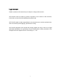
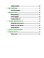
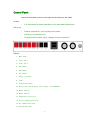
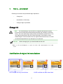
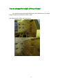
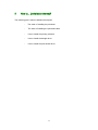
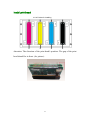
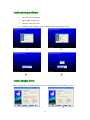
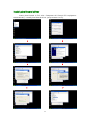
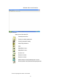
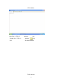
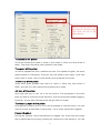
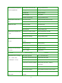
Ultra 4000 4H PRINTER USER MANUAL USER MANUAL 1 Legal statement Details contained in this manual may be subject to change without notice. WIT-COLOR would not make any kinds of sponsion to the content in this document, include but not only the merchantability and special used. WIT-COLOR would not take responsibility for the document error and the stochastic loss, which is caused by and supplying, performance or using. WIT-COLOR equipment user manual and printing program are only for the use of legal authorized individuals. No reproduction may be made without written permission from Shanghai Wit-Color Digital Science & Technology Co, .LTD. 2 Table of contents 1 Brief Introduction................................................................................................................... 5 Use the manual.............................................................................................................. 6 Main parts................................................................................................................... 7 Control Panel.............................................................................................................. 9 Safety notice............................................................................................................. 10 Hold notice ............................................................................................................... 13 2 How to...(Basic operation theme)........................................................................................ 15 Contact to computer ................................................................................................. 15 Turn on/off Power ................................................................................................... 16 3 How to install media............................................................................................................ 17 Put the media coil in printer ...................................................................................... 18 Media holder use...................................................................................................... 19 4 How to...(Ink theme)............................................................................................................ 20 Change ink barrel ..................................................................................................... 20 Identification of original ink manufacturer ................................................................. 20 Change height of printhead ...................................................................................... 21 5 How to...(Installation theme) ............................................................................................. 22 Install printhead ........................................................................................................ 23 Install printhead cable .............................................................................................. 24 Install printing software............................................................................................. 25 Install dongle driver .................................................................................................. 25 3 Install pixel board driver ........................................................................................... 26 6 How to...(Software theme) .................................................................................................. 27 ULTRA382 series software ..................................................................................... 27 7 How to get the best picture ................................................................................................... 40 Mechanical adjustment............................................................................................. 41 Printhead adjustment ............................................................................................... 42 Print mode parameter chart...................................................................................... 48 8 Tell me about...(Basic requirement theme) ......................................................................... 50 Workshop Environment requirement ........................................................................ 51 Workshop power supply requirement ....................................................................... 52 Computer requirement ............................................................................................. 52 9 The problem is...(Failure recovery theme) .......................................................................... 53 10 Tell me ahout...(Help theme) ................................................................................................ 57 Customer service ..................................................................................................... 57 4 1 Brief Introduction Use the manual Heat and dry The printer of the front board Safety notice Notice for picking up 5 Use the manual The manual include follows. Brief instruction In this section, we provide simple instruction about printer and documents to new user. How to… In these sections, we will instruct user how to operate with some illustration, such as how to take media coil and change ink barrel. The problem is… In these sections, we could help you to solve problem. Tell me about… In these sections, we provide some information; include printer size, media type, and the series NO. of other parts. Index In these sections, we provide some information; include printer size, media type, and the series NO. of other parts. 6 Heat and dry The printer includes six heaters, we can make the media pictures stable based on them. Each heater can be controlled individually. Mid-heating (heating2) Pre-heating (heating1) Dry heating (heating3) Material WARNING! Don't touch the heater, or you will be scalded. 7 Media feed and take-up Material Take-up system Shift switch NOTICE! Shift switch Attention to the direction of winding. 8 Feeding system Control Panel Control Panel located on the front and right side of the printer, with follow function: · It is necessary for some operation, such as media feeding and taking-up. · Display information, such as the power state. · Guide you to use the print. · Change some number value, change the print operation. Follows: 1. Main power 2. Front fan 1 3. Front fan 2 4. Pre-heater 5. Mid-heater 6. Dry heater 7. Blank ( useless) 8. Light 9. Vacuum fans power 10. Burner cap voltage power (only supply for ULTRA4000) 11. Media feeding 12. Media take-up 13. Temperature controller 14. Pre-dry temperature knob 15. Dry temperature knob 16. Vacuum fans knob 9 SAFETY NOTICE There are following signs in the manual to insure the printer is used correctly and no damaged. Please follow the explanation of these signs. WARNING!If don't follow this sign, perhaps you will be hurt grievously or die. CARE!If don't follow this sign, perhaps you will be hurt slightly or damage machine. COMMON WARNING · · Using the prescriptive voltage to avoid the power over loading. To make sure the printer touches the ground well, otherwise, it may lead to electric shock, fire, parts damaged and EMI. · Don't disassemble and repair the printer by yourself. Don't reinstall printer in a new place. If you have any problems, please contract to Wit-Color distributors. · Only using the power wire that Wit-color approbated. Don't damaged, cut or repair the power wire, otherwise, maybe lead to fire, electric shock or parts damaged. · Don't let inside parts touch metal or liquid(except for cleaning), otherwise, it may lead to fire, electric shock, parts damaged or other dangers. · Please cut off power and pull out power wire in following situations: · To touch the inside printer by your hands. · Printer is smoky or smelly. · The printer makes abnormal noises when the printing is normal. · Inside parts of the printer touch metal or liquid(except for cleaning). · Storm weather(thunder/lighting). · Power has something wrong. · There has organic solvent in inks and cleaning solutions. So please follow the local law about organic solvent taking, using, storing and managing. · Ink and cleaning solution is inflammable substance. So the printer and the ink should keep 8M (25feet) away from fire, spark, or other ignition source. 10 Don't operate printer in distance of 8M(25feet) from fire, spark, or other ignition source. Don't smoking in distance of 8M (25feet) from fire, spark, or other ignition source. · Installing and operating the printer in drafty area. · Please following all the principles about VOC discharge. We suggest you installing air cleaner. Before ink-fog discharge, please get permit from local air quality control agency. · TO avoid ink touching eyes, skin and clothes. If happened: · Cleaning the skin with soap immediately. · Getting off the clothes with ink to avoid touching skin. · If the ink spatters into your eyes, please clean with safe eye-cleaner or clean water and see doctor if necessary. · Don't swallow inks. If swallowed, don't try to vomit, please to see a doctor immediately. · Please keep the ink tank, the cleaning suite and the waste ink away from children. · All of operators must be trained to use urgency equipment, such as extinguisher, and know where they are. COMMON ATTENTION · Taking media coil carefully. They are too weighty to move in narrow space. Sometimes, it should be moved by 2 men. It may fall down and hurt somebody or damage the printer. · Around the printer to leave enough room to get safety equipment quickly, such as extinguisher. · All of the media, the cleaners and the rags with ink are inflammable substance. Please picking up and handle them correctly. · If air cleaner installed, please keep enough spaces for print's vent-pipe contacting. 11 Locating air clean and vent-pipe system to avoid open circuit and interfere print work, when media taking up, feeding and ink tank checking, changing. · When pull out power wire, Please always hold plug to fix wire, but not hold wire directly. Otherwise, maybe lead to electric shock, fire. · Don't touch the surface of the media in the heater, or you will be scalded.. For safe work, please pay attention to all "ACRE" and "WARNING". 12 Notice for picking up Please pay attention to the introduction, so that you can avoid damaging the printer and parts. Power · Using the pointed power voltage. · To check power socket before connecting to the printer, and make sure the polarity touches the ground well, otherwise, it may cause electric shock, fire, parts damaged and EMI. · To guaranteeing the printer touches the ground well, otherwise, it may cause electric shock, fire, parts damaged and EMI · To avoiding the power over loading. · Only using the power wire that be approbated by Wit-Color. Printer · You can use soft fabric and neutral detergent to clean the printer. Don't spill liquid into printer; otherwise, it may cause electric shock, fire or parts damaged, so that the printer can't work normally. Don't dilute cleaning solution with benzene or dope. It may damage the coating of printer. · Don't touch nozzles, it's easy to damage and clog. Inspection and maintenance regularly · Please follow the maintenance principle. See How to maintain. · Cleaning the covering everyday. · Turning off printer in right process. Consumable · Ink is inflammable substance. Don't take it near fire, spark, or other ignition source. · Please use the ink before its period of validity. If you use the ink after the period of validity two months, the quality of the ink will be declined. · TO avoid ink touched eyes, skin and clothes. If happened: · Cleaning skin with soap and clear water immediately. · Getting off clothes with ink for avoiding touching the skin. 13 · Please clean ink-splashed eyes with safe eye-cleaner or clean water and see doctor if necessary. · Storing the ink in cool and dry place, it can keep ink quality in its period of validity 14 2 How to… (Basic operation theme) ? · Contact to computer · Turn on/off Power Contact to computer The following part is about system configuration and the process of contact cable and wires. NOTICE! Before connect or cut off SCSI cable, please turn off the power of printer and computer. System configuration(contact example) Following work could be done 1. Install pixel board and transfer into computer. 2. Contact pixel board to printer by SCSI cable. 3. Contact transfer to Encoder Stripe by 50PIN cable. 15 Turn on/off Power WARNING! Please use the power wire that is approbated by Wit-Color. To make sure the printer touches the ground, or it will cause electric shock, fire, parts damage and EMI. CARE!When pull out power wire, please always hold plug to fix wire, but not hold wire directly. Otherwise, maybe lead to electric shock, fire. Turn on power 1. Turn off printer by power switch in the right of printer. One end of power wire plug in socket of printer, other one plug in socket of power. WARNING! You need to avoid the power over loading. Only using the power wire is approbated by Wit-Color. Don't damage, cut or repair the power wire, otherwise, it may cause fire, electric shock, parts damaged. 2. Turn on power switch ON Process of turn on power 1 ON 10 Turn off power OFF Process of turn off power: 10 OFF 16 1 3 How to install media The Following part is how to install media into printer. · How to put the media coil in the printer · Media holder use · How to use media feeding and take up system 17 Put the media coil in printer CARE! Don't touch heater for avoiding scalding. Taking media coil carefully because they are too weighty to move in narrow space. It should be moved by 2 men. It may fall off to hurt somebody or damage the printer. NOTICE! According to the media thickness, you should adjust the height of the printhead. See” Change printhead height”. When media coil installs, please make sure that the truckles are stable. (Press down brake handle) Material 18 The usage of media holder Set up the holder on two side of workplace to reduce the possibility of printhead knock against. Based on the width of media, we can adjust the position of the holder. 19 4 How to... (Ink theme)? Following is ink theme and printhead height adjustment. · Change ink · Identification of ink factory · Change height of printhead Change ink CARE! You should always use the inks from original manufacture because these inks are researched and developed specially and certified by printhead factory. We could realize high quality printing and reliable operation with it. The non-original manufacturer ink may cause low quality, some faults or some hidden dangers. Wit-Color didn’t test non-original manufacturer inks, so we will not be held responsible for any damage by non-principal. NOTICE! Before changing ink, you should shake the ink well. Name(Y:Yellow,M:Magenta,C:Cyan,K:black,LM:Light magenta,LC:Light cyan) Identification of original ink manufacturer WITCOLOR ink only-used sticker XAAR certified anti-fake laser label 20 How to change the height of the printhead You could adjust printhead height according to the media thickness. The best distance between printhead and media is 3MM. The following part is about operation process 21 5 How to... (Installation theme)? The following part is about installation description · The order of installing the printhead · The order of installing the printhead cable · How to install the printing software · How to install the dangle driver · How to install the pixel board driver 22 Install printhead 4H-4C Order for installing Attention: The direction of the print head’s position. The gap of the print head should be in front. (As picture) 23 Install printhead cable The order of connecting the print head and the carriage terminal control board. To insert the adapters A, B from the cable into the corresponding position on the print head. And to insert the other end A1/A2/B1/B2 into the corresponding position on the carriage terminal control board. 24 Install printing software 1、 Put CD into computer. 2、 Open [My computer] 3、 Double click CD icon. 4、 Double click [setup] icon, c link[next](as process A to D). A B C D Install dongle driver After click [yes], install dongle driver, click [install] (as process A to B) A B 25 Install pixel board driver Insert pixel board in PCI slot. Computer will found PCI equipment automatically. Install pixel board driver (as process A to P). A B C D E F 26 6 How to... (Software theme)? The following parts are about how to use the printing and RIP software. · Ultra printing software operation. Ultra polaris ☆Tips software use System time can’t be changed, or else, dangle will be locked. 1、 Summary Wit-Color printer is controlled by Ultra Control Center software. This software could operate files RIP to RTL, PRN and PRT formats. Every formats file could be printed in low, middle and high speed mode. Every speed mode has 4 resolution modes. Viscosity could be changed within limited. PHOTOPRINT RIP software is recommended. About RIP software, please see corresponding RIP software use manual. 2、 Software guide Double click Ultra 382 maxH8 Control Center software icon to open software. Carriage will move to left slowly and stop on the position of printhead cleaning, until touched limited switch. The software main control interface will come on desktop (see6.1.7.). Initialization is finished. 27 Software main control interface Keys instruction: Open picture files after RIP Closed pictures files Printing as setting parameter Printing parameter setting Adjust edge-distance Help Magnified 4 times Magnified 2 times Normal view Reduced 2 times Reduced 4 times Media advance and printhead power control Moved position and printhead testing adjustment Control program menu structure 28 File menu Open files... CTRL+O same as key Closed files... CTRL+C same as key Exit Exit Ultra software Print menu 29 File info: Image information: Folder location, files size, image width and length, RIP resolution, etc. N o ti c e ! This menu could be entered after picture opening Print option : Printer mode, printer speeds, printer density, segment spacing, jet bars and auto cleaning jet pack, etc. 30 When you open the software the first time,you must keep purge cycle on,set the time as the image showing The mode of the printer The three modes are mode 0, mode 1 and mode 2. Click one from three of them. The One with black point presents the mode. The speed of the printer The three speeds are slow, medium and fast. The speed is higher; the more requirements of machinery, electron, and ink quality are higher. Click one from three of them; the one with black point presents the mode. The density of the printer There have three grades from 100% to 150% 3. Click one from three of them, and the one with black point presents the mode. Jet bars of the printer Click [jet bars on] to turn on or off the printer. The purposes of the print bars are that to check the work status by eye and avoid printhead clogging. And also, the jet bars calculate the margin and the width. The cleaning cycle of the printer Click [purge cycle] to turn on or off the printhead on the flat board. You can input the time as seconds by keyboar d. It’s to avoid printhead clogging. Pause L/R-adjust During the printing, the printhead will be logged. You must stop and p urge the printhead before printing continually. Because of the machine, you will 31 find the edges will not a line. The error could be reduced by input correct values. Segment spacing According to media width, segment could be printed automatically by program. [Edge overlap] must be adjust by inputting a value in segment printing, furthermore, [between segments] must be adjusted by inputting a value in continuous segment printing. Encoder select 1、 internal encoder: General servo locating 2、 optical encoder: Optical locating 3、 magnetic encoder: Magnetic locating (We do not use now.) Auto cleaning jet pack [Every( )Passes] for inputting the values of every how many passed for one time auto cleaning. [Movement adjust( ) ]for adjusting error of auto dust collector ☆Tips Click [OK] to confirm before exit. ☆Tips Click [Cancel] to exit with original set. Select area: Set quantity of segments according to media width to print segment separately or continuously, or print input rectangle area. In every segment, the start row could be pointed. 32 Print image: It displays all the printer parameter for checking. For example, the print speed, pause to clean and adjust media advance, etc. 33 View menu Toolbar(T) Display tools Status Bar(S) Display status Statistic(T) Count print sizes Zoom in/out(Z) Magnified/Reduced image Display Black(D) Display black in YMCK Display Bitmap(B) Display opening files(default to on) Utilities menu 34 Configure: Same as key Resolution Color mode Size and unit Speed Print mode Control: Same as Printing direction Key Motor option Print head voltage option 35 Calibration: Same as Key Calibration 1 : [Set clean station point] is to set position of clean. The input value is the distance from limit switch to left side of carriage. Carriage will stop on this position in next beginning. [Movement init dist] is to set the range of carriage from rest to work speed or from work speed to rest. Generally, the input value is higher than actual range, but don’t set it so high that reduce effective range. [Movement L delay] is to set the delay distance from ordering to move, to beginning move to left. More big Input value, more big range image move to right.[Movement R delay] is to set the delay distance from ordering to move, to beginning move to right. More big value Input, more big range image move to left. If the mechanical resolution is good enough in X-axis, right and left delays will be almost same and realized alignment of right and left sides. NOTICE! This function is used to inside coder 36 [Y-Stepping Adjust] is to micro-adjust Y-axis moving. So many elements will make media advance error, such as material, pressure from media hold ring, pull from medi a take-up system, etc. The error could be reduced by input a nonzero value. [Bi-Alignment] is to micro-adjust alignment of two sides in X-axis. NOTIC! This function is used to encoder. NOTIC ! Different materials, different printer modes, different resolutions and printing direction all make different media advance and different set. 37 Calibration 2 : Printhead software adjustment NOTICE! Printhead adjustment could be read in Teaching Materials Measure: Same as Key Measure media width automatically (Depend on Configure) Manual input media width Manual change media layout 38 Help menu About (A) same as 39 key 7 How to get the best picture · Mechanical adjustment · Printhead adjustment · Print mode parameter chart Different media makes different quality picture. So in order to optimize quality, before printing with one kind of media, you can test it first, and then adjust printer according to the result of testing to print. 40 Mechanical adjustment ◆Tools: Dial indicator and Minpad (others needed) ◆ Operation: Dial indicator: Fix dial indicator on slide. According to reads in dial indicator, push or pull screws (under plate), until the reads on the left, middle and right of work plate are all same. Minpad: Put two minpads between printhead plate and work plate (two sides’ measure). To adjust the distances between printhead plate and work plate are all just minpad’s thickness 3 MM in every pieces of work plate, permit error 0.5 MM. That’s OK. ◆ Importance: Levelness of work plate will influence directly the resolution of images. Such as : The resolution in right and left sides will be different in same print mode. The pleats in media caused by media hold rings forcing unevenly, maybe scrape carriage. NOTICE!Mechanical adjustment must be done after new installation NOTICE!Mechanical adjustment must be done after media hold rings installation finished ☆Tips Work plate is horizontal means printhead plate is perpendicular to linear rail 41 ☆Tips Parameter A on the back side of Certification is for reference only. Printhead adjustment 4H-4C adjustment method A. Printhead installs position B. How to switch the software in Ultra Polaris You can choose four or six color in Color Mode. After you finish, close the software and open again. Attention: for Ultra4000-4H printer,you must select Color Mode by YMCK. c. How to operate the software First step: Double click and open the software go to the calibration 2. 42 Second step: To adjust the direction of print head Y. To get test strip (above) according to click The print head Y make explain to the test strip. 43 The right way of adjusting the print head Y’s position: a. To adjust the print head as a straight line, then the repeated area, Y, C and K overlap M. The standard picture as follow: (the position of the print head is moved by the screw, all the chromatic line be overlapped in the dashed border.) The following picture is unqualified, you should adjust again. Third step: To adjust the position of print head X. To get the following test strip according to click 44 The print head Y make explain to the test strip: From right to left From left to right The result of adjusting should be: all the lines which are corresponding to +0 and -0 overlap. The right picture as follow: (from left to right, the blue one as an example.) 45 From left to right If +0 and -0 are not on a same line, you should adjust: From left to right NOTE: 1. from left to right to print, K is the standard, and other print heads’ positions are: C=B/Y=C/M=D. 2. from right to left to print, M is the standard, and other print heads’ positions are: Y=b/C=c/K=d. From the test strip, -1 that is between C and K overlapped. Then we open the calibration 2 to find the corresponding position. The position of micro adjust: B. The value of micro adjust: -1. After finishing it, the click repeatedly or the value Attention: Don’t click will be added. 46 And so on. Forth step: To adjust the position of 4 print heads in the group. To print the test strip based on. From left to right to print, the forth print head is the standard. From right to left to print, the first print head is the standard. For example: Then we find the corresponding position. The position of micro adjusts: K1. The value of micro adjusts: -1. After finishing it to click 47 Attention: Don’t click repeatedly, or the value will be added. And so on. Print mode parameter chart Notice:resolution was depond on the encoder stripe (dpi) and printhead (dpi). The original resolution of encoder stripe has 180dpi and 150dpi two type. The original resolution of printhead is 200dpi. So in the software.360*200,720*200.720*600… support to 180dpi encoder stripe. And 300*200^600*200,600*400……support to 150dpi encoder stripe, The type of encoder stripe can be checked by the number which on the stripe. Equipment Resolution Mode 4000 4H Pass quantity Mode0 1 Pass Mode1 2 Pass Mode2 4 Pass 720X*200dpi Mode0 1 Pass 600*200dpi Mode1 2 Pass 360*200dpi 300*200dpi 48 Mode2 4 Pass Mode0 2 Pass Mode1 4 Pass Mode2 8 Pass Mode0 2 Pass Mode1 4 Pass Mode2 8 Pass Mode0 3 Pass Mode1 6 Pass Mode2 12 Pass Mode0 3 Pass Mode1 6 Pass Mode2 12 Pass 360*400dpi 300*400dpi 720*400dpi 600*400dpi 360*600dpi 300*600dpi 720*600dpi 600*600dpi NOTICE: For print a good image.we suggest you to choose the correct resolution in the ripping software(maintop or photoprint). which resolution is better for you? Depond on the printhead`s ink picoliter:15pl and 35pl. 15pl printhead,the ink density is lower than 35pl printhead, so for X-axis resolution,please don't use 300dpi or 360dpi,using 600dpi and 720dpi is better. And 35pl printhead printer can use both. List: 15pl printhead printer 35pl printhead printer 150dpi stripe 180dpi stripe 150dpi stripe 180dpi stripe 600*400dpi 720*400dpi 300*400dpi 360*400dpi 600*600dpi 720*600dpi 300*600dpi 360*600dpi 600*800dpi 720*800dpi 300*800dpi 360*800dpi 49 8 Tell me about... (Basic requirement theme) The following part is about information of printer control. Please know these knowledge before read others. · The information about environment requirement · The information about power supply requirement · The information about computer requirement 50 Workshop Environment requirement The following is about environment requirement Install space Hold enough space for ventilation, picture output and repair, to put some frequently-used parts. Environment requirement Please print in following environment: Temperature:18℃ - 25℃ Humidity:45% - 75% NOTICE! Picture maybe low quality, not be printed in required environment. The position printer can’t be installed. Don’t install printer in following environment: · Direct sunlight · Always quacked · Much dust · Temperature and humidity change sharply. · Closed to air-conditioner and other heaters · Printer may be damp. · Directly influence by air cycle from vent. · Insufficient ventilation 51 Workshop power supply requirement Voltage: 220V, 50 HZ Single-phase alternating current, Max.Power: 3000W. DC power is supported by a separated circuit breaker. Earthing is separated from other equipments. Requirement: 3KV UPS power.( self-configuring) . Computer requirement Control Station:Windows XP/windows 7 32bits (do not support Vista) Main board: ASUS brand:Three PCI card port and with COM port. CPU: Inter core II 5200 more…… RAM: Kingston DDR II 2G Hard Disk:SATA 500G (7200rpm) Graphic Card: Separate Disk-C Space: 100G File System: NTFS NOTICE! Above are the requirements of computer at least, otherwise, it may get some problems. 52 9 The problem is... (Failure recovery theme) Symptom All printheads don’t inkjet Reasons perhaps Solutions No voltage Check all powers and board voltage Data-signal system problem Check cables and boards in data-signal system Printhead damage Change a new printhead for testing Individual printhead don’t Cables and adapters damage Exchange other normal parts for testing inkjet Individual data-signal system Check cables and boards in data-signal problem system Printhead damage Exchange other normal parts for testing Internal encoder is work, but The position of encoder sensor Put encoder stripe in the middle of encoder optical encoder is doesn’t work and encoder stripe is wrong sensor Scratch or other mechanical Change encoder stripe damages in encoder sensor Encoder sensor light is bright or Change encoder sensor not Ink supply cut-off Encoder system problem Check cables and boards in encoder system Height of ink tank is not correct Adjust height of ink tank Static electricity problem Test and connect the ground again Humidity / temperature reach Measure humidity / temperature of equipment requirement or not “Drop ink” comes in printing process Regular depth-light lines come Ink reach requirement or not Check ink viscosity and period of validity Printhead ageing Change a new or good printhead Ink tank is too high (ink level is too Lower ink tank, lower ink level high) Static electricity problem Test and connect ground again correctly Impurity on printhead surface Scrub printhead with special wipes Printhead damage or not Change printhead Carriage plate is vertical or not Reduce mechanical error in permit 53 to X-axis in image Quantity purged are different from Exchange printhead position printheads Thick stripes come in Y-axis in Resonance comes to equipment Exchange printhead position image So much vibration on Linear rail maintain linear rails and slides Computer get stuck when Computer’s Install a fresh computer system or change fault computer open software Pixel board damage Change pixel board Software can’t be opened, Other software is working in “CTRL+ALT+DEL” to Task Manage computer prompt nothing processes Computer time is normal or not Dongle damage Check LPT in main board is on or Turn on LPT in BIOS off Symptom Software can’t be opened, Reasons perhaps 24V power problem Check 24V power light is normal or not in computer prompt: Home movement failed Solutions terminal board Servo problem Following servo prompt Pixel board problem Software could be opened by press limit switch, no servo prompt Limit switch doesn’t work, but D3 light in pixel board is normal. Software can’t be opened: Right limit signal lamp in pixel Change PCI socket, scrub connector fingers Right limited switch activity board is abnormal with eraser Change pixel board Software can’t be opened: Right limit signal lamp in pixel Change PCI socket, scrub connector fingers left limited switch activity board is abnormal with eraser Change pixel board Software installation finish, Software is correct or not Check software pixel board driver install Computer PCI socket problem Change computer of PCI socket unsuccessfully Pixel board problem Change pixel board 54 Second ink tank is empty and Ink level sensor fault in ink tank Change ink level sensor can’t be supplied inks Ink supply board fault Change ink supply board Ink pump fault Change ink pump Filter is clogging Change filter Printhead board damage Change printhead board Ink pump don’t work in first Air go into ink pump Injected inks with syringe into pump time Ink pump fault Change ink pump Heater don’t work Heater is no power Check the power Solid relay damage Change solid relay Heater damage Change heating parts Temperature controller damage Change temperature controller Short circuit in heating system Check and repair heating system Heating protect damage Change heating protect Color process is inaccurate in X-axis Parameter is wrong in Set parameter anew. X-axis software Temperature Controller don’t work Gearing is worn out Change gearing Motor damage Change motor Carriage moves quaveringly Diver wire jumper Set driver correctly too much Diver’s Change diver Symptom faults Reasons perhaps Solutions Limit switch is pressed Don’t press limit switch don’t back to start Limit switch connector short circuit Contact limit switch again position(don’t move) Didn’t turn on power switch Turn on power switch X-axis motor or its driver problems Change motor and driver(Notice to After printer turn on, carriage Annunciator) SCSI cable poor contact Check SCSI cable Moving system problem Check cables and board in moving system After printer turn on, carriage Limit switch or its connector are Change switch and connectors bump to left. damaged 55 The times of carriage staying Other processes come to To avoid other processes come to computer, in right and left sides are computer, while printing while printing different, while printing. Computer is reach to requirement Change and improve computer or not 56 10 Tell me about... (Help theme) Customer service For connect to us expediently, following is Wit-Color service system: 1) Please read Wit-Color user manual to get helps directly. 2) Looking for technology support in our website ( www.wit-color.cn) .We will support the latest problems and its solutions. 3) Calling to Wit-Color or local distributor. 4) Calling to Wit-Color after-sale service department. Work time:8:00-17:30 ( Beijing Local Time) 5) Technology support website : www.wit-color.cn Email: [email protected] Wit-Color after-sale service TEL: 86-021— 54881617 FAX: 86-021— 54881617 Complaint center Mobile: 86 18017197711 Email: [email protected] 6) We suggest you send us fault photo if you can. 57