1
Revision:
Oct. 2012 (English)
For software versions:
1.43X
SMART
CALIBRATION RECORD
Record the calibration settings in the following table.
Serial Number:
Model:
Operating Voltage:
230 V/50 Hz / 12VDC (optional for IP65)
Purchase Date:
Installation Date:
Calibration Coefficients:
ZERO:
SPAN:
Factory Access Code (ID):
2802
Personalized Access Code (ID):
WARNING
Keep this number in a safe place. This will be the only one that will let you
access the protected parameters (scale definition, calibration and others)
i
SMART User’s Manual
SAFETY PRECAUTIONS
WARNING-SHOCK HAZARD
For proper grounding, the power connector must only be
mated with a three-wire grounded receptacle.
WARNING-SHOCK HAZARD
For proper grounding, the safety ground wire (green or
green/yellow) must be connected to the general ground
wire.
WARNING-SHOCK HAZARD
Due to the risk of electrical shock, this instrument must
be installed only by qualified personnel.
WARNING- SHOCK HAZARD
Due to the risk of electrical shock, the cover must be
removed only by qualified personnel.
CAUTION
Power is immediately applied when the power cord is
plugged into a live receptacle.
CAUTION
Calibration and configuration must be performed only by
qualified personnel.
CAUTION
Electrical shock hazard. Do not remove cover. Refer
servicing to qualified personnel.
CAUTION
Risk of fire. Replace fuses with the proper spare.
CAUTION
The integrated circuits in the SMART are sensitive to
electrostatic discharge (ESD). Be sure to follow proper
procedures for transporting, storing and handling ESDsensitive components.
ii
SMART User’s Manual
INDEX
1
Introduction…..……………………………………………………….1-1
1.1
1.2
1.3
1.4
1.5
1.6
2
Indicator Characteristics ................................................................................... 1-1
1.1.1
Load Cell Connection .............................................................................. 1-1
1.1.2
Operator Interface ................................................................................... 1-1
1.1.3
Serial Communications............................................................................ 1-1
1.1.4
Input/Output Options ............................................................................ 1-1
1.1.5
Power ...................................................................................................... 1-2
1.1.6
Environmental and Mechanical................................................................ 1-2
Keyboard .......................................................................................................... 1-2
Display and Luminous Information .................................................................... 1-3
1.3.1
Functions ................................................................................................ 1-3
Label with characteristics and metrological identification................................... 1-4
Error Messages ................................................................................................ 1-5
Maintenance ..................................................................................................... 1-6
1.6.1
Replacing Fuses ..................................................................................... 1-6
1.6.2
Cleaning .................................................................................................. 1-6
Operation…….……………………………………………………….2-1
2.1
2.2
2.3
2.4
2.5
Turning the indicator on .................................................................................... 2-1
Entering Values ................................................................................................ 2-1
Normal Weighing .............................................................................................. 2-1
Zero .................................................................................................................. 2-2
Tare .................................................................................................................. 2-2
2.5.1
Activate tare ............................................................................................ 2-2
2.5.2
Clearing a Tare Value ............................................................................. 2-2
2.6
Ticket Printout................................................................................................... 2-2
2.7
Piece Counting ................................................................................................. 2-3
2.8
Accumulation .................................................................................................... 2-3
2.9
Setpoint ............................................................................................................ 2-4
2.10
Communications ............................................................................................... 2-5
2.10.1
General Characteristics of the Remote Controller .................................... 2-5
2.10.2
Protocol RS-232 .....................................................................................2-10
2.10.3
Network Communications (RS-485) .......................................................2-10
2.11
Automatic operations ports Rx/Tx and Tx ........................................................2-11
2.12
Remote display ................................................................................................2-11
3
Configuration and Calibration………..………………………….….3-1
3.1
3.2
Introduction....................................................................................................... 3-1
Scale Definition................................................................................................. 3-3
3.2.1
Operation (funct) .................................................................................. 3-4
3.2.2
Range (birange) .................................................................................. 3-4
3.2.3
MAX (cap) .............................................................................................. 3-4
3.2.4
DIV (d1) .................................................................................................. 3-4
3.2.5
DP (dp) ................................................................................................... 3-4
3.2.6
MAX1 (cap1) .......................................................................................... 3-4
3.2.7
DIV1 (d11) .............................................................................................. 3-4
3.2.8
DP1 (dp1) ............................................................................................... 3-4
3.2.9
MAX2 (cap2) .......................................................................................... 3-4
3.2.10
DIV2 (di2) .............................................................................................. 3-4
3.2.11
DP2 (dp2) ............................................................................................... 3-4
iii
SMART User’s Manual
3.3
3.4
3.5
3.6
3.7
iv
3.2.12
ZERO TRACK (0-trac) ......................................................................... 3-5
3.2.13
ZERO RANGE (0-top) ........................................................................... 3-5
3.2.14
AUTO ZERO (0-start) ......................................................................... 3-5
3.2.15
NEG-ZERO(0-neg) ................................................................................. 3-5
3.2.16
UNITS (unit) .......................................................................................... 3-5
Options.............................................................................................................. 3-6
3.3.1
FILTER (filter) .................................................................................... 3-6
3.3.2
MOT BAND (band) .................................................................................. 3-7
3.3.3
TARE LOCK (tareloc) .......................................................................... 3-7
3.3.4
LANGUAGE(lang ) ................................................................................. 3-7
3.3.5
KEY LOCK (loc) ..................................................................................... 3-7
3.3.6
PRINT MIN (prt)..................................................................................... 3-7
3.3.7
TICKET(prt_t1)..................................................................................... 3-8
3.3.8
TOTALIZATION TICKET (tot_t1) ......................................................... 3-8
3.3.9
TICKET_ID (tid)..................................................................................... 3-8
3.3.10
ACCESS CODE (pin) ............................................................................. 3-8
Communication Port (Rx/Tx) ............................................................................. 3-9
3.4.1
MODE (type) .......................................................................................... 3-9
3.4.2
BAND(band).......................................................................................... 3-10
3.4.3
FORMAT (For) ...................................................................................... 3-10
3.4.4
BAUD (baud)......................................................................................... 3-10
3.4.5
PARITY (par) ........................................................................................ 3-10
3.4.6
DELAY (del) ......................................................................................... 3-10
3.4.7
TERMINATION (ter) ............................................................................ 3-10
3.4.8
CONTROL (cntl) ................................................................................. 3-10
3.4.9
PROT (prot)......................................................................................... 3-11
3.4.10
ADD (add) ............................................................................................. 3-11
Transmission Port (Tx) .................................................................................... 3-11
3.5.1.
MODE(type) ......................................................................................... 3-12
3.5.2.
BAND (band)......................................................................................... 3-12
3.5.3.
FORMAT (for) ...................................................................................... 3-12
3.5.4.
BAUD (baud)......................................................................................... 3-12
3.5.5.
PARITY (par) ........................................................................................ 3-12
3.5.6.
DELAY (del) ......................................................................................... 3-12
3.5.7.
TERMINATION (ter) ............................................................................ 3-12
3.5.8.
CONTROL (cntl) ................................................................................. 3-13
Analog Output ................................................................................................. 3-13
3.6.1
TYPE(type) .......................................................................................... 3-14
3.6.2
OFFSET (offset) ................................................................................ 3-14
3.6.3
ERROR (error).................................................................................... 3-14
3.6.4
MIN (aout_0)........................................................................................ 3-14
3.6.5
FULL (aout_f) ..................................................................................... 3-14
3.6.6
TW MIN (aout_f0) ............................................................................... 3-14
3.6.7
TW FULL (aout_ff) ............................................................................. 3-14
Digital outputs ................................................................................................. 3-15
3.7.1
D_OUT Nº (d_out n)............................................................................ 3-15
3.7.2
VL(i) (ul) ............................................................................................... 3-15
3.7.3
TYPE(i) (type) ...................................................................................... 3-16
3.7.4
REL(i) (rel) ........................................................................................... 3-16
3.7.5
TRIP(i) (trip) ....................................................................................... 3-16
3.7.6
BAND(i) (bd) .......................................................................................... 3-17
SMART User’s Manual
3.7.7
HYSTERESIS(i) (hy)..............................................................................3-17
3.7.8
LOCKED (D_LOC) ..................................................................................3-17
3.7.9
OUTPUT(i) (output) .............................................................................3-17
3.8
Digital Inputs ....................................................................................................3-19
3.8.1
D_IN NUM (d_in no)...........................................................................3-19
3.8.2
TYPE(i) (type) ......................................................................................3-19
3.8.3
FUNCTION(i) (func) .............................................................................3-20
3.9
Calibration with Masses ...................................................................................3-21
3.9.1
ZERO (0ero) .........................................................................................3-21
3.9.2
SPAN (span) .........................................................................................3-22
3.9.3
TW SPAN (fspan).................................................................................3-22
3.9.4
LIN, LIN_C y LIN_I (lin,lin_c,lin_1) ................................................3-22
3.10
Numerical Calibration ......................................................................................3-24
3.10.1
LCAP (lcap)..........................................................................................3-24
3.10.2
LNUM (lno) ...........................................................................................3-24
3.10.3
L Sn (lsn)..............................................................................................3-24
3.10.4
ZERO (0ero) .........................................................................................3-24
3.11
Animal-weigher/Check-weigher application......................................................3-25
3.11.1
Init (init) ..............................................................................................3-26
3.11.2
Delay time (t_del) ................................................................................3-26
3.11.3
Weight readings time (t_acc)................................................................3-26
3.11.4
Display time (t_dis) .............................................................................3-26
3.12
Tools ...............................................................................................................3-27
3.12.1
Weightx10 (h_res) ................................................................................3-27
3.12.2
MV-Metro (signal) ...............................................................................3-27
3.12.3
Print Cal (p_cal) ...................................................................................3-27
3.12.4
SMART Parameter List...........................................................................3-28
3.12.5
Par.Reset (preset) ...............................................................................3-30
3.12.6
Brightness of LEDs (led int) ..............................................................3-30
3.12.7
Date(date) ............................................................................................3-30
3.12.8
Hour(hour) ............................................................................................3-30
4
Installation…………………………………………………………….4-1
4.1
4.2
4.3
4.4
5
Measures.......................................................................................................... 4-1
Fixed Bracket ................................................................................................... 4-2
Unit Label ......................................................................................................... 4-3
IP65 Assembly.................................................................................................. 4-4
Connector Description……………………………………………….5-1
5.1
Load cell Connector .......................................................................................... 5-1
5.1.1
Load cell connector sealing ..................................................................... 5-2
5.2
Communication Connectors.............................................................................. 5-2
5.2.1
RS-232 (Rx/Tx) Connector ...................................................................... 5-2
5.3
IP65 Connections ............................................................................................. 5-3
5.4
Multioption connection ...................................................................................... 5-4
5.5
RS-232 (Tx) Connector ..................................................................................... 5-5
5.6
Digital/Analog input/Output and RS-485 connector ........................................... 5-5
5.7
IP65 Multioption connection .............................................................................. 5-6
5.8
RS-232/RS-485 change jumper for Multioption ................................................. 5-6
5.9
RS-232 Jumpers’ position for Multioption .......................................................... 5-7
5.10
Remote Display Connection ............................................................................. 5-7
v
Introduction
1
1.1
1.1.1
Introduction
Indicator Characteristics
Load Cell Connection
Full scale input signal
Input impedance
Internal resolution
Measurement rate
Linearity error
Zero stability
Span stability
Excitation voltage
Transducer minimum resistance
Transducer maximum resistance
Wire length
Input overload
1.1.2
Operator Interface
Main display
Keyboard
1.1.3
7 digit LED 20 mm
Keyboard with 6 keys
Serial Communications
Port Tx/Rx:
Optional
Transmission rates
Number of bits and parity
1.1.4
±3 mV/V
200 MΩ (typical)
Converter AD 24 bits,16700000 counts
(± 8350000)
50 measurements per second
≤ 0.01 % of measurement level
150 nV/ºC max.
3.5 ppm/ºC max.
6.1 ± 0.5 VDC
85Ω (4 cellsx350Ω, 8 cellsx700Ω)
1000 kΩ
400 m/mm2 max. (6 wires)
30 m/mm2 max. (4 wires)
± 12 V
Bi-directional RS-232C
RS-485, RS-232C only transmission
19200, 9600 and 4800 bauds
8 bits no parity, 7 bits even parity and 7 bits odd
parity
Input/Output Options
4 digital inputs
4 digital outputs
Analog output
VILOW = 0.8V; VIHIGH = 2V; VIMAX = 30V
Open collector outputs; VOLOW = 0.5V
VOHIGH = VEXT – 1.2V; IILOW = 200mA (max)
Range VEXT = 5V – 24V
Galvanic insulation output, 14-bits D/A
Voltage output: 0 –10.5V (nom); load > 1kΩ
Current output: 0 – 21mA; loop resistance<500 Ω
1-1
Introduction
1.1.5
Power
Power supply
Fuse
Alimentation DC (optional for IP65)
1.1.6
Environmental and Mechanical
Operating temperature
Storage temperature
Size
Weight
Mounting
1.2
230 VAC ±10%, 50 Hz, 6 W max.
250 V, 100 mA slow fusion
7.5V - 15VDC, nominal 12V.
External fuse 500mA
-10ºC a 40ºC
-25ºC a 70ºC
282 x 158 x 71 mm (stainless steel version)
282 x 159 x 75.5 mm (ABS version)
1.85kg (stainless steel version)
1.1kg (ABS version)
Bench mount or bracket
Keyboard
The keyboard is on the front side of the equipment and has 6 keys.
These are the main functions of these keys:
Keys
Normal status
Setup
Exit any operation
Upwards
0
Zero the scale
To the left
(Cursor)
T
Enter stored tare
To the right
(Cursor)
Piece counting
Increase one digit
(Cursor)
Accumulation
Decrease one digit
(Cursor)
Print ticket
Confirm a value
EXIT
1-2
Introduction
1.3
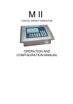
Display and Luminous Information
The indicator consists of a main display and seven luminous indicators, as shown in
figure 1.3.1.
Figure 1.3.1 Display and luminous Information
1.3.1
Functions
Indicator
Σ
/
Meaning
Tare
Scale is in standstill mode
Zero
Pieces mode
Accumulation
Range situation
1-3
Introduction
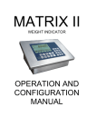
1.4
Label with characteristics and metrological identification
It is on the rear side of the indicator, as shown in figure 1.4.1. It is a safety label which
contains the characteristics of the device, and metrological values and marks.
Figure 1.4.1 Label with characteristics and metrological identification layout
1-4
Introduction
1.5
Error Messages
Main display
Condition
Solution
Scale is not empty
Remove the weight
EEPROM failure
Contact your technical service
Data memory failure
Contact your technical service
No signal from the load cell
Check connector and load cell cable
ADC error
Check connector and load cell cable
ADC failure
Contact your technical service
Weight exceeds the maximum
capacity
Enter signal exceeds the
maximum range
Enter signal under the minimum
range
Weight on the scale under the
minimum weight
Remove weight
Not accomplished:
MAX
≤ 100000
DIV
MAX
Not accomplished:
≤ 100000
DIV
Not accomplished:
MAX 1
≤ 100000
DIV 1
Not accomplished:
MAX 1
≤ 100000
DIV 1
Not accomplished:
MAX 2
≤ 100000
DIV 2
Not accomplished:
MAX 2
≤ 100000
DIV 2
Check installation
Check installation
Put a weight above the minimum value
(see 3.3.6)
Check that MAX value is correct
Change DIV to acomplish the relation
Check that DIV value is correct
Change MAX to acomplish the relation
Check that MAX1 value is correct
Change DIV1 to acomplish the relation
Check that DIV1 value is correct
Change MAX1 to acomplish the relation
Check that MAX2 value is correct
Change DIV2 to acomplish the relation
Check that DIV2 value is correct
Change MAX2 to acomplish the relation
Invalid zero value entered
Change zero value
Power failure
Check power supply
The maximum number of
calibrations has been reached
Unplugged
Fuse has blown
Indicator failure
Contact your technical service
Plug it in
Replace fuse
Contact your technical service
1-5
Introduction
1.6
1.6.1
Maintenance
Replacing Fuses
If displays do not appear when it is connected to power, the problem may be a
defective ac power fuse. Replace the defective fuse as specified below.
a.
b.
c.
d.
e.
Disconnect the indicator by pressing the rear switch and unplug the equipment from the
electric outlet.
Disconnect the power cord from the rear side of the equipment.
Stainless steel version: Extract the fuse by pulling out the small tab of the fuseholder,
which is in the rear side of the equipment.
ABS version: Extract the fuse by unscrewing the fuseholder, which is in the rear side of
the equipement.
Change the damaged fuse for a new one according to the specifications in 1.1.5.
Close the fuseholder and connect the equipment.
If the equipment is configured as IP65, replace the fuse as specified below.
a.
b.
c.
d.
e.
f.
Disconnect the indicator from the power plug.
Remove the rear cover by unscrewing the screws.
Remove the fuse protecting cover, which is in the power source.
Remove the fuse by pulling it out carefully.
Change the damaged fuse with a new one according to the specifications shown in 1.1.5,
and reinstall the protecting cover.
Close the equipment and connect it.
WARNING- SHOCK HAZARD
Due to the risk of electrical shock, the cover must be
removed only by qualified personnel.
1.6.2
a.
b.
Cleaning
Disconnect the indicator by pressing the rear switch and unplug the equipment from the
electric outlet.
Clean the indicator with a clean and dry cloth.
CAUTION
• Never use alcohol or solvents to clean the indicator.
These chemical products could damage it.
• Make sure that water does not enter the indicator. It
could damage electronic components.
1-6
Operation
2
2.1
Operation
Turning the indicator on
To turn the indicator on, you must connect the equipment to the power supply and activate the
rear switch. The switch on sequence will first display a display test countdown sequence, then
the software version, the equipment serial number, and finally the number of performed
calibrations.
Figure 2.1.1 Switch on sequence
It would be better to stabilize the equipment for a while before using it, especially
before a calibration. In this case it is advisable to wait for 30 minutes. The equipment may be
permanently connected in order to avoid warm up time and potential condensations in case of
significant changes in the outside temperature.
2.2
Entering Values
To use some of the equipment functions, it is necessary to introduce numerical values.
Use the arrow keys to introduce these values. Use right and left arrow keys to position onto the
digit to be modified, and the up and down arrow keys to increase or decrease its value.
2.3
Normal Weighing
When loading the platform, the measured weight is displayed on the display.
2-1
Operation
2.4
Zero
The indicator has a zeroing manual mechanism. When you press the Zero key the
indicator stores the current weight value as the zero of the system.
This key acts depending of how we have defined the 0-top (see 3.2.13).
Operation:
0
2.5
2.5.1
Tare
Activate tare
Press the Tare key. The current value will be stored as tare. The NET led lights
Operation:
T
2.5.2
Clearing a Tare Value
To clear a tare register in normal operation, that is to say when the tare lock option is
on (see 3.3.3), press Exit and then the Tare key.
Operation:
→
T
EXIT
If the tare lock is off then the tare is automatically deactivated if the conditions
described on 3.3.3 are accomplished.
2.6
Ticket Printout
Press the Print key to print a ticket. If the weight is under the divisions introduced in PR
MIN function (see 3.3.6), the auxiliary display shows“
Operation:
Ticket ID:
Gross
Tare
Net
1
100.0 kg
0.0 kg
100.0 kg
Figure 2.6.1 Ticket example
2-2
”.
Operation
2.7
Piece Counting
Place a certain number of pieces on the scale, press the Piece Counting key and enter
the number of pieces on the scale. The PCS led lights. From now on the indicator displays the
number of pieces.
Operation:
→No.pieces→
Press Exit and then the Piece Counting key to exit this function.
2.8
Accumulation
This function adds up various weights and gives the number of accumulated weights.
To add the weight that is on the scale into the sum press the Accumulation key.
In order to see the number of weighings, press again the Accumulation key before
losing the stability. If you press this key again, the accumulated total will be displayed. If the
piece counting function is activated, the sum of pieces is displayed.
Operation:
Record the current weight on the scale
Record the current weight on the scale and see the number of accumulated weighings
Record the current weight on the scale and see the total value accumulated
To leave this function press Exit, and then the accumulation key. The total
accumulated and the number of weights will be set to zero.
EXIT
Each time we press
a ticket is being printed where is showed, for every
keystroke, the number of weighing and its corresponding weight.
2-3
Operation
On leaving this function the total accumulated weight is printed.
Figure 2.8.1 shows a ticket example.
Ticket No.
12345-
Total:
2
100.0 kg
200.0 kg
300.0 kg
400.0 kg
500.0 kg
1500.0 kg
Figure 2.8.1 Ticket example
2.9
Setpoint
(Accessible menu only after having installed the digital output accessory)
Pressing the Exit and Tare keys at the same time you access the menu where you can
introduce the weight with which the selected output operates.
Operation:
T
EXIT
Inside the Value level we can find the parameters that are shown in the figure:
Figura 2.9.1 Setpoint
Use the key arrows to move through the menus. Press the Enter and Exit keys to
change the level. If you want to modify a selected parameter, press the Enter key and
introduce the new value with the up and down arrow keys (
) or choose and option (
2-4
),
Operation
as appropiate. Press Enter to accept. Press Exit if you want to exit the menu without making
any changes.
Exit:
EXIT
When parameter d_loc i is on then the message loc (locked) will be shown and
blink three times, this parameter can not be modified from this menu.
2.10 Communications
This equipment has one serial communication port:
Port Rx/Tx:
transmission and reception serial port
The communication channel can be configured from the Configuration Menu (see 3.4).
A second transmission channel is available as an optional extra.
The performance of the second communication channel can be configured from the
Configuration Menu (see 3.5).
2.10.1
2.10.1.1
General Characteristics of the Remote Controller
Remote Controller Commands
The equipment can be controlled through the Rx/Tx port. To carry out this function
the indicator must be configured in ‘DEMAND’ mode (see 3.4.1).
Operation Commands:
A
Query/Set weight in F4 format
G
Equivalent to EXIT + TARE keys
P
Query/Set weight with response according to the selected format (see 3.4.3)
Q
Equivalent to PRINT key
R
Reset system
T
Equivalent to TARE key
Z
Equivalent to ZERO key
S
Equivalent to Σ key
E
Equivalent to EXIT + Σ keys
$
Weight query/set: The command does not require <CR>
STX, ENQ, ETX
Weight query: the command does not require <CR>
SYN
Weight query: the command does not require <CR>
SETPOINTS Programming: It allows to change the VL(i) parameter from the i digital output
(see 3.7.2).
The decimal point is taken from the system.
In case of TYPE(i) = ±REL o ±%REL: VL(i) = pppppp/100 %.
Program:
S
P
i
±
Consult:
S
P
i
?
p
p
p
p
p
p
p
It returns the value in the programmed format.
2-5
Operation
Data transfer in ASCII format:
±:
i :
p:
REMOTE Mode:
Sign: + positive value; - negative value
Digital output number (1 - 4)
Weight (7 digits)
It allows changing the i digital output, provided that
this is programmed TYPE(i) = REM (see 3.7.3)
Act:
X
O
i
Consult:
X
O
?
x
Answer:
X O x8 X7
X6 X5
X4
X3
X2
Data transfer in ASCII format:
i :
Digital output number (1 - 4)
xn :
Status of the digital output (n): 0 = OFF; 1 = ON
Read digital inputs:
It allows reading the status of the digital inputs
Consult:
X
I
?
Answer:
X I
x8
X7 X6 X5 X4 X3 X2
Data transfer in ASCII format:
xn:
Status of the digital input (n): 0 = Low; 1 = High
Consult the number of weighings accumulated:
Command: SN
Answer:
number of weighings
space + 7 digit ASCII ('0 '... '9')
‘‘
N
N
N
N
N
N
N
Consult the total weight accumulated;
Command: ST
Answer:
Total weight accumulated
sign + 7 digits ASCII ('0 '... '9') without decimal point
+
P
P
P
P
P
P
Consult total weight and number of accumulated weighings
Command:
#<ADR>SQ<CR>
Answer:
Length 8 bytes
- 1st byte: address + offset (0x20)
example: equipment address = 12:
1st byte value = 12 + 128 = 140 (symbol ASCII: ‘'î'’)
2-6
X1
length 6 bytes
P
X1
Operation
- 2nd, 3rd and 4th byte: weight accumulated in pseudo binary, offset = 0x20
example: totalized weight = 458901
2nd byte high-nibble = 4, low-nibble = 5:
byte value = 4*16 + 5 + offset = 64 + 5 + 32 = 101 (symbol ASCII: ‘A’)
3rd byte high-nibble = 8, low-nibble = 9:
byte value = 8*16 + 9 + offset = 128 + 9 + 32= 169 (symbol ASCII: ‘®’)
4th byte high-nibble = 0, low-nibble = 1:
byte value = 0*16 + 1 + offset = 33 (symbol ASCII: ‘!’)
- 5th, 6th and 7th byte: number of totals in pseudo-binary, offset = 0x20
example: totalized weight = 000005
5th byte high-nibble = 0, low-nibble = 0:
byte value = 0*16 + 0 + offset = 0 + 0 + 32 = 32 (symbol ASCII: ' ')
6th byte high-nibble = 0, low-nibble = 0:
byte value = 0*16 + 0 + offset = 0 + 0 + 32 = 32 (symbol ASCII: ' ')
7th byte high-nibble = 0, low-nibble = 1:
byte value = 0*16 + 5 + offset = 0 + 5 + 32 = 37 (symbol ASCII: '%')
- 8th byte: end character CR (0x0d, 13 decimal)
2.10.1.2
Data Format
F1 Format:
<STX>
POL
F2 Format:
‘’
POL
ppppppp
nnnnnnn
F3 Format:
<STX>
‘1’
‘‘
G/N
S
T
T
‘0’
‘’
F4 Format:
POL
aaaaaaa
T
F5 Format:
<STX>
‘’
nnnnnnn
POL
U
POL
nnnnnnn
<ETX>
T
<ETX>
T
F6 Format:
For UTILCELL remote display. The content of the display is transmited in
hexadecimal.
D7
D6
D5
D4
D3
D2
D1
Status
T
Digit code:
bit 7:
bit 6:
bit 5:
bit 4:
bit 3:
bit 2:
bit 1:
bit 0:
A
segment DP
segment A
segment B
segment C
segment D
segment E
segment F
segment G
F
G
E
B
C
D
DP
2-7
Operation
Status code:
bit 7:
bit 6:
bit 5:
bit 4:
bit 3:
bit 2:
bit 1:
bit 0:
accumulation activated
range 1 (R1)
range 2 (R2)
piece counting activated
preset tare (PT)
ZERO
NET
STABLE
Format F7:
<STX>
status
POL
ppppppp T
The status is obtained when you add to 0x20hex the values of the lighted status LEDs:
Gross= 0x01hex
Zero= 0x08hex
Net= 0x02hex
Standstill=0x20hex
Format F8:
<STX>
POL ‘ ‘
UNITS:
ppppppp ‘ ‘
Unit
kg = ‘KG’
lb = ‘lb’
Unit
MODE:
Format F9:
ppppppp
T
Format F10:
<STX>
<STA>
<STA>:
status, 1 character: "+"
"-"
"?"
Format F11:
<STX> ‘ ‘
‘‘
‘‘
Format F12:
<STX>
<STA>
<STA>:
weight:
weight:
2-8
T
positive weight
negative weight
unsteady weight
POL
ppppppp
T
““
weight
T
status, 1 character: "S"
steady weight
"N"
unsteady weight
without decimal point 6 digits
with decimal point 7 digits
Format F13:
<STX>
<STA>:
ppppppp
““
<STA>
weight
T
status, 1 character: "S"
steady weight
"N"
unsteady weight
without decimal point 5 digits
with decimal point 6 digits
‘‘
Mode Mode ‘ ‘
Gross= ‘BR’
Net= ‘NT’
T
Operation
Format F14:
-length 6 bytes
-1st byte: address + offset (0x20)
example: equipment address = 12:
1st byte value = 12 + 32 = 44 (symbol ASCII: ',')
-2nd byte: high-nibble of total, low-nibble sign + offset (0x20)
example 1: no totals = 0; positive weight = 1:
byte value = 0*16 + 1 + offset = 0 + 1 + 32 = 33 (symbol ASCII: '!')
example 2: there are totals = 1; nehative weight = 0:
byte value = 1 * 16 + 0 +offset = 16 + 0 + 32 = 48 (symbol ASCII: '0')
possible values:
Weight
Totals
2nd byte value
positive
no
0x21
positive
yes
0x31
negative
no
0x20
negative
yes
0x30
-3rd, 4th and 5th byte: net weight in pseudo binary, offset = 0x20
example: net weight = 009894
3º byte high-nibble = 0, low-nibble = 0:
byte value = 0*16 + 0 + offset = 0 + 0 + 32 = 32 (symbol ASCII: '0')
4º byte high-nibble = 9, low-nibble = 8:
byte value = 9*16 + 8 +offset = 144 + 8 + 32 = 184 (symbol ASCII: ‘©’)
5º byte high-nibble = 9, low-nibble = 4:
byte value = 9*16 + 4 + offset = 144 + 4 + 32= 180 (symbol ASCII: ‘┤’)
-6º byte: end character CR (0x0d, 13 decimal)
Definitions:
<STX>
Start of Text (ASCII 2)
<ETX>
End of Text (ASCII 3)
<ENQ>
Enquire (ASCII 5)
<SYN>
Synchronous Idle (ASCII 22)
<CR>
Carriage Return (ASCII 13)
<LF>
Line Feed (ASCII 10)
‘‘
Space character
‘0’
Character ‘0’
‘1’
Character ‘1’
ppppppp
Weight value, 7 characters
nnnnnnn
Net weight value, 7 characters
aaaaaaa
Analog/Digital converter filtered output, 7 characters
POL
Polarity:
‘‘
Weight > 0
‘-‘
Weight < 0
U
Units:
K
kg
T
t
G
g
L
lb
‘‘
oz, without unit
G/N
Gross/Net:
G
Gross
2-9
Operation
S
T
ACK
NAK
2.10.2
N
Net
Status:
‘‘
Valid
M
Motion
O
Overload
I
Invalid
Termination:
CR
CR + LF
(ASCII 6)
(ASCII 21)
Protocol RS-232
Communication between two equipments, point per point, with a maximum distance
of 15 m.
Protocol format:
Command CR
All commands in section 2.10.1.1.
2.10.3
Network Communications (RS-485)
(For applications with the Input/Output accessory)
Communication between several equipments (100 maximum) in a BUS with a
maximum link distance of 1,200 m.
The SMART indicator can only be the SLAVE and it must be assigned a unique
address from 1 to 99.
Masters queries and slaves responses have the following formats:
Master query:
#
Dd
CR
Termination (CR fix)
Command
Address(2 bytes decimal, see 3.4.10)
Start master query
Slave response:
>
Dd
TERMIN
Termination (see 3.4.7)
Response
Address(2 bytes decimal, see 3.4.10)
Start slave response
There are three types of responses:
Data
ACK
2-10
Received and responded query command
Received and understood command
Operation
NAK
Received but not understood command
2.11 Automatic operations ports Rx/Tx and Tx
When the option MODO (type) of the recepción/transmisión port (Rx/Tx) or the
transmission port (Tx) is AUTO, autoti or autoto (see sections 3.4 and 3.5) then the
indicator is configured to carry out automatic operations in one of the ports or in both.
The values to configure for the automatic operations are prt (see sections 3.3.6) and
BAND (see sections 3.4.2 and 3.5.2).
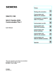
The mode of operation can be seen in figure 2.11.1: the value of the weight goes
increasing until it arrives to the value of minimum weight (prt) at time T1. Once the weight is
superior to prt the automatic operation will take place once there is stability and time passes
the one defined in del (see 3.4.6 and 3.5.6), and this happens at T2. Starting at T3 the weight
passes below the value of prt but the automatic system won't be reactivated until it doesn't
decrease the weight to the value of BAND, and this happens at T4.
WEIGHT
prt
BAND
T1
DEL
T2
T3
T4
TIME
Figure 2.11.1 Automatic operations
2.12 Remote display
To operate the indicator as a Remote display, it should be activated in the equipment
configuration (see 3.2.1). After activating the equipment, it will only operate as a remote display
of another indicator, which should be connected according to the specifications in 5.10.
Configure the following parameters to establish a communication between the
equipments:
Parameters
FORMAT
BAUD RATE
PARITY
DELAY
TERMIN
CONTROL
Indicator
Remote display
Fixed at F6
Make values equal
Fixed at 8n
Fixed at 250ms
Fixed at CR
Fixed at OFF
See 3.4.3
See 3.4.4
See 3.4.5
See 3.4.6
See 3.4.7
See 3.4.8
2-11
Operation
Note: We should configure the indicator as a STREAM (st ) mode (See 3.4.1). The
indicator’s configuration can be made in the communication port Rx/Tx (See 3.4) as in the
transmission port Tx (See 3.5). In the repeater the configuration port only can be made in the
communication port Rx/Tx.
If the communication is not successful, a line of segments will be displayed
(
2-12
)
Configuration and Calibration
3
3.1
Configuration and Calibration
Introduction
Configuration and calibration modes have different parameters:
-Free access, they can always be read and modified.
-Protected, they can always be read but only modified under certain conditions (tagged
with a
in the diagrams).
Calibration and configuration modes can be activated by pressing the Setup key and
). If you do
zero key simultaneously. Then the indicator requests the access code (
not enter this code (and press Enter) or if you enter a wrong code, you access the menu but
without permission to modify the protected parameters.
The access code can be modified (see 3.3.10). Its value can be consulted by means
of printing the parameters. It is highly recommended to print the parameters after the process
of calibration of the indicator and keep it with the equipment documentation.
It is possible to prevent mechanically the
access to the protected parameters by
means of the JP3 jumper of the indicator
main board. If A and B pins are bridged, the
system is mechanically unprotected. If B
and C pins are bridged, the system is
mechanically protected.
Figure 3.1.1 JP3 Detail
If a protected parameter is changed, the new value is recorded. The indicator displays
the number of calibrations made until then.
You will find the access code on page i.
Figure 3.1.2 shows the basic menu structure.
3-1
Configuration and Calibration
H_res Signal P_cal Preset
Ledint Date Hour
init t_del t_acc t_dis
D_loc
tareloc
Pin
Figure 3.1.2 Basic Menu Structure
Within the calibration and configuration menu, the display shows your position.
Use the key arrows to move through the menus. Use the left and right arroy keys
(
) to move within the same level, and press the Enter and Exit keys to change the level. If
you want to modify a selected parameter, press the Enter key and introduce the new value with
) or choose and option (
), as appropriate. Press Enter
the up and down arrow keys (
to accept. Press Exit if you want to exit the menu.
We recommend printing the calibration parameters after configuring the system using
the P_cal function from the options submenu.
3-2
Configuration and Calibration
3.2
Scale Definition
Within the Scale Definition configuration level, parameters showed in Figure 3.2.1 can
be found.
def
funct
indica repeat
birang e
cap
on off
cap1
di
dp
1 2 5 10 20 50
dii
dpi
1 2 5 10 20 50
cap2
di2
dp2
1 2 5 10 20 50
0-trac
off 05d 1d 2d
0-top
0-star t
19 100
0-neg
on off
on off
unit
kg t g lb o none
Figure 3.2.1 Scale Definition
3-3
Configuration and Calibration
3.2.1
Operation (funct)
It selects the operation mode of the equipment.
These are the options:
Indica:
Operation in the indicator mode
Repeat:
Operation in the remote display mode (See 2.12)
3.2.2
Range (birange)
Activates the Multiple Ranges function. In ON position, the menu allows the access
to MAX1, DIV1, DP1, MAX2, DIV2 and DP2 parameters, and MAX, DIV and DP2 disappear
from the menu (see 3.2.1).
3.2.3
MAX (cap)
Maximum capacity of the scale.
3.2.4
DIV (d1)
Value of the scale division.
3.2.5
DP (dp)
Position of the decimal point. By pressing the arrow keys you can move the decimal
point to the desired position so that the division of the scale would be in the same unit than the
capacity of the scale.
3.2.6
MAX1 (cap1)
The capacity for Range 1.
3.2.7
DIV1 (d11)
The Division for Range 1.
3.2.8
DP1 (dp1)
Position of the decimal point for Range 1. By pressing the arrow keys you can move
the decimal point to the desired position so that the division for the Range 1 would be in the
same unit than the capacity.
3.2.9
MAX2 (cap2)
The capacity for Range 2 (=total capacity)
3.2.10
DIV2 (di2)
The Division for Range 2. By pressing the arrow keys you can move the decimal
point to the desired position so that the division for the Range 2 would be in the same unit than
the capacity.
3.2.11
DP2 (dp2)
Position of the decimal point for Range 2.
3-4
Configuration and Calibration
3.2.12
ZERO TRACK (0-trac)
The level at which the system is automatically zeroed as long as the weight is within
the selected band.
These are the options:
OFF:
Deactivated function
0,5dd:
± 0.5 divisions
1dd:
± 1 division
2dd:
± 2 divisions
3.2.13
ZERO RANGE (0-top)
The range within which the scale may be zeroed (
key and zero track).
These are the options:
1.9%:
Allows performing a zero if the weight value is ≤1.9% of the maximum
capacity.
100%:
Allows performing a zero for the 100% of the maximum capacity.
3.2.14
AUTO ZERO (0-start)
The indicator zeroes when it is turned on.
These are the options:
ON:
Activated function
OFF:
Deactivated function
3.2.15
NEG-ZERO(0-neg)
The indicator goes to zero automatically when the weight value is negative and
remains stable for more than 5 seconds.
These are the options:
OFF:
Deactivated function
ON:
Activated function
3.2.16
UNITS (unit)
Weight unit of the scale.
These are the options:
kg:
kilogram
t:
ton
g:
gram
lb:
pound
o:
ounce
none:
none
3-5
Configuration and Calibration
3.3
Options
Within the Options configuration level, parameters showed in Figure 3.3.1 can be
found.
optio ns
filte r
Off 2 4 8 16 32 64
tare loc
band
Off 1d 2d 3d
l oc
spa
por
fre
prt_ti
prt
Off
000000
tid
On off
lang
est
Prog
eng
ger
cat
tot_ti
Off
est
Prog
PI N
PI
0 0 0 0
P 2
0 0 0 0
Figure 3.3.1 Options
3.3.1
FILTER (filter)
Filter level. You can choose among different levels or deactivate this function. The
higher is the selected value, the higher is the filter level.
These are the options:
OFF, 2, 4, 8, 16, 32, 64
3-6
Configuration and Calibration
3.3.2
MOT BAND (band)
The level at which motion is detected. Out of this level there is no stability.
These are the options:
OFF:
Deactivate function
1dd:
One division
2dd:
Two divisions
3dd:
Three divisions
3.3.3
TARE LOCK (tareloc)
Allows activating and deactivating the tare lock.
Its possible options are:
On, off
If that option is on the tare is locked (keeps the tare). That is the equipment default
option and under which the tare is activated until it is manually deactivated (see 2.5.2). Whe
that option is off the tare acts as follows: if after removing the weight its value is within the
range of ¼ divisions around zero then the equipment automatically deactivates the tare.
3.3.4
LANGUAGE(lang )
You can choose among different languages for the printed ticket.
The possible options are:
SPA:
Spanish
POR:
Portuguese
FRE:
French
ENG:
English
GER:
German
CAT:
Catalan
3.3.5
KEY LOCK (loc)
Locks the keyboard. The parameter treatment is performed with a 6 digit binary
number. The value 1 locks the function and the value 0 releases it.
These are the options:
5|4|3|2|1|0
KEYB - LOCK
PRINT - LOCK
TARE - LOCK
ZERO - LOCK
PCS - LOCK
TOTAL - LOCK
3.3.6
Keyboard lock
PRINT key lock
TARE key lock
ZERO key lock
PIECES key lock
TOTAL key lock
PRINT MIN (prt)
Minimum weight value in divisions at which a print ticket request may be accepted. If
the ticket cannot be printed “
” will be displayed.
3-7
Configuration and Calibration
3.3.7
TICKET(prt_t1)
Select the type of ticket to be printed with the Print key.
These are the options:
OFF:
No ticket printing
EST:
Standard ticket
PROG:
Preset ticket
3.3.8
TOTALIZATION TICKET (tot_t1)
Select the type of ticket to be printed with the Accumulation key.
These are the options:
OFF:
No ticket printing
EST:
Standard ticket
PROG:
Preset ticket
ATTENTION FOR PRESET TICKETS
From software versión 1.024 there are 7152 bytes to store tickets.
Older versions the available memory is 3053 bytes. Keep in mind when
creating format tickets to keep the printing files (*.prn) or text files
(*.txt) below that value.
To transfer the preset tickets to the indicator will be necessary the
SmartMatrix Ticket program.
3.3.9
TICKET_ID (tid)
Edit the number of the next printing ticket. Up to 5 digits can be modified.
3.3.10
ACCESS CODE (pin)
With this option we can modify the access code value. The modified value has to be
correctly introduced twice.
Pin_err
If the introduced values are different, the message
is showed and
the process has to be begun from scratch.
WARNING
Keep this number in a safe place. This will be the only
one that will let you access the protected parameters
(scale definition, calibration and others)
3-8
Configuration and Calibration
3.4
Communication Port (Rx/Tx)
Within the communication port (transmission/reception), parameters showed in Figure
3.4.1 can be found.
S E RI A L
B A ND
T YPE
De st Ti
F OR
Auto Autot
F1 F2 F3 F4 F5 F6 F7
F8 F9 F10 F11 F12 F13
B A UD
P AR
8n 7e 7o
4800 9600 19200
T ER
Crlf Cr Et None
D EL
C N TL
On Off
Off 250 500 1000
P roT
rs-232
2000
ADD
Rs-485
Figure 3.4.1 Communication port
3.4.1
MODE (type)
Transmission mode.
These are the options:
DEMAND (de):
Data transmission on external request through the serial port
STREAM (st):
Continuous data transmission
TICKET (ti):
On a print internal request (Print key)
AUTO (auto):
It is automatically transmitted on acomplishing the condition for
automatic operations on ports (see 2.11). The transmission
format is the one specified in Format (see 3.4.3)
3-9
Configuration and Calibration
AUTO TICKET (autoti):
AUTO TOTAL (autoto):
3.4.2
A ticket is automatically printed on acomplishing the º
condition for automatic operations on ports (see 2.11).
Totalizes automatically on acomplishing the condition
for automatic operations on ports (see 2.11).
BAND(band)
Only accessible if the options AUTO, AUTO TICKET and AUTO TOTAL are activated
in the MODE parameter.
It is the numerical value which determines the band of performance for the options
AUTO, AUTO TICKET and AUTO TOTAL of the MODE parameter.
3.4.3
FORMAT (For)
Format of transmitted data for DEMAND and STREAM.
These are the options:
F1, F2, F3, F4, F5, F6, F7, F8, F9, F10, F11, F12, F13
3.4.4
(See 2.10.1.2)
BAUD (baud)
Transmission speed.
These are the options:
4800, 9600, 19200
3.4.5
PARITY (par)
Number of data bits and parity.
These are the options:
8-none:
8 bits data
7-even:
7 bits data, 1 bit even parity (even)
7-odd:
7 bits data, 1 bit odd parity (odd)
3.4.6
DELAY (del)
It is the delay time from the request to the data transmission. If configured in STREAM
mode, it is the delay time between the transmitted data.
These are the options:
OFF, 250ms, 500ms, 1s, 2s
3.4.7
TERMINATION (ter)
Termination of the data for DEMAND and STREAM.
These are the options:
CR+LF
<CR>,<LF>
CR
<CR>
ET
<ETX>
NONE
NOTHING
3.4.8
CONTROL (cntl)
Control of the hardware flow (RTS signal of the RS-232-C protocol)
These are the options:
OFF:
Deactivated function
ON:
Activated function
3-10
Configuration and Calibration
3.4.9
PROT (prot)
Communications protocol selection (see 2.10). If “RS-232” is selected, the ADD
parameter is forced to be “0”.
3.4.10
ADD (add)
Address of the equipment in a RS-485 network. It has to be “0” to operate as a RS-232
port.
3.5
Transmission Port (Tx)
(Accessible menu only after having installed the RS-232 second port accessory)
Within the configuration transmission port, parameters showed in Figure 3.5.1 can be
found.
p ri n te r
t yp e
b an d
for
OFF st ti auto autot
b au d
4800 9600 19200
ter
Crlf Cr Et None
f1 f2 f3 f4 f5 f6 f7
f8 f9 f10 f11 f12 f13
del
p ar
8n 7e 7o
Off 250 500 1000 2000
c nt l
on Off
Figure 3.5.1 Transmission Port
3-11
Configuration and Calibration
3.5.1.
MODE(type)
Transmission mode.
These are the options:
OFF (off):
Data transmission deactivated
STREAM (st):
Continuous data transmission
TICKET (ti):
Transmission on a print internal request (Print key)
AUTO (auto):
It is automatically transmitted on acomplishing the condition for
automatic operations on ports (see 2.11). The transmission
format is the one specified in Format (see 3.5.3)
AUTO TICKET (autoti):
A ticket is automatically printed on acomplishing the º
condition for automatic operations on ports (see 2.11).
AUTO TOTAL (autoto):
Totalizes automatically on acomplishing the condition
for automatic operations on ports (see 2.11).
3.5.2.
BAND (band)
Only accessible if the options AUTO, AUTO TICKET and AUTO TOTAL are activated
in the MODE parameter.
It is the numerical value which determines the band of performance for the options
AUTO, AUTO TICKET and AUTO TOTAL of the MODE parameter.
3.5.3.
FORMAT (for)
Format of transmitted data for STREAM.
These are the options:
F1, F2, F3, F4, F5, F6, F7, F8, F9, F10, F11, F12, F13
3.5.4.
(see 2.10.1.2)
BAUD (baud)
Transmission speed.
These are the options:
4800, 9600, 19200
3.5.5.
PARITY (par)
Number of data bits and parity.
These are the options:
8-none:
8 bits data
7-even:
7 bits data, 1 bit even parity (even)
7-odd:
7 bits data, 1 bit odd parity (odd)
3.5.6.
DELAY (del)
It is the delay time from the request to the data transmission. If configured in STREAM
mode, it is the delay time between the transmitted data.
These are the options:
OFF, 250ms, 500ms, 1s, 2s
3.5.7.
TERMINATION (ter)
Termination of the data blocks.
These are the options:
3-12
Configuration and Calibration
CR+LF
CR
ET
NONE
3.5.8.
<CR>,<LF>
<CR>
<ETX>
NOTHING
CONTROL (cntl)
Control of the hardware flow (RTS signal of the RS-232-C protocol)
These are the options:
OFF:
Deactivated function
ON:
Activated function
3.6
Analog Output
(Accessible menu only after having installed the Analog Output accessory)
Within the analog output configuration level, parameters showed in Figure 3.6.1 can be
found.
a_out
type
offset
gross net
0 20
aout_0
aout _f
erro r
full hold 0ero
aout_f0
aout_ff
Figure 3.6.1 Analog Output
3-13
Configuration and Calibration
3.6.1
TYPE(type)
Weight value of analog output signal.
These are the options:
GROSS:
Gross weight value is taken as reference
NET:
Net weight value is taken as reference
3.6.2
OFFSET (offset)
Analog output zero offset.
These are the options:
0% y 20%.
Note: For a 4-20mA or 2-10V output we should set the OFFSET value at 20%.
3.6.3
ERROR (error)
Output in case of system error.
These are the options:
FULL:
Output = MAX
HOLD:
Hold the output to the current value
ZERO:
Output = MIN
3.6.4
MIN (aout_0)
Minimum capacity of the analog output range.
3.6.5
FULL (aout_f)
Maximum capacity of the analog output range.
3.6.6
TW MIN (aout_f0)
Fine adjustment of the minimum analog output. Modify the level pressing the arrow
keys.
3.6.7
TW FULL (aout_ff)
Fine adjustment of the maximum analog output. Modify the level pressing the arrow
keys.
Figure 3.6.7.1 Typical Analog Output Scaling
3-14
Configuration and Calibration
3.7
Digital outputs
(Accessible menu only after having installed the Digital Outputs accessory)
Within the digital outputs configuration level, parameters showed in Figure 3.7.1 can be
found.
d _out
d_ou t
n
ul
type
off gross net p_rel n_rel p_prel n_prel 0ero
0net ss inrang neg tare print tot pc_ctr
1 2 3 4
trip
rel
1 2 3 4
bd
hy
h l in_b out_b
d_lo c
outp ut
off on
off 1 2 3 4
Figure 3.7.1 Digital outputs
3.7.1
D_OUT Nº (d_out n)
Select the number of output.
These are the options:
1, 2, 3, 4
3.7.2
VL(i) (ul)
Value with which the selected output operates.
3-15
Configuration and Calibration
3.7.3
TYPE(i) (type)
Type of output action.
These are the options:
OFF (off):
GROSS (gross):
NET (net):
+REL (p_rel):
-REL (n_rel):
+%REL (p_prel):
-%REL (n_prel):
ZERO (0ero):
ZERONET (0net):
SS (ss):
INRANGE (inrang):
NEG (neg):
TARE IN (tare):
PRINT (print):
SUM (tot):
PC_Ctr (pc_ctr):
3.7.4
Deactivated
Gross weight value as reference
Net weight value as reference
Setpoint trips on the absolute setpoint value, VL(i),
plus the relative value, REL(i)
Setpoint trips on the absolute setpoint value, VL(i),
minus the relative value, REL(i)
Similar to +REL/-REL except the setpoint trips on the
absolute setpoint value plus a percentage of the
relative value
Similar to +REL/-REL except the setpoint trips on the
absolute setpoint value minus a percentage of the
relative value
The output trips if a zero is in the system
The output trips if the net mode is activated and the
display shows a zero
The output trips if the scale is in the Standstill state
The output trips if the weight value is within ±MAX
The output trips if the weight value is under zero
The output trips if a tare is in the system
The output trips while printing
The output trips if there is a sum
Output controlled by the serial port
REL(i) (rel)
It defines the reference SETPOINT number on which ±REL or ±%REL are applied. It
should be considered that the output number that we are defining must be higher than the
reference number. If this condition is not fulfilled, the error message “rel_err” will appear on
the auxiliary display.
These are the options:
1, 2, 3, 4
3.7.5
TRIP(i) (trip)
Setpoint trip action.
These are the options:
H:
Trip when weight<VL(i)
L:
Trip when weight >VL(i)
IN_B:
Trip hen weight>VL(i)+BD(i) or weight<VL(i)-BD(i)
OUT_B
Trip when VL(i)-BD(i)<weight<VL(i)+BD(i)
If the digital output is set in the PC_Ctr mode of the TYPE(i) parameter (see 3.7.3),
when you turn on the equipment the output configuration is determined by this operation mode.
HIGH:
ON
LOW:
OFF
3-16
Configuration and Calibration
3.7.6
BAND(i) (bd)
A numerical value which determines the value of the IN_B and OUT_B selections of
the TRIP parameter.
3.7.7
HYSTERESIS(i) (hy)
Determines the hysteresis value which prevents chattering of the digital output
3.7.8
LOCKED (D_LOC)
It blocks the modification of VL(i) value through the keyboard (see 2.9)
3.7.9
OUTPUT(i) (output)
Associates a physical digital output with a setpoint (see 5.6). If you try to assign more
than one setpoint to a digital output, the message “out_err” is displayed.
These are the options:
OFF, 1, 2, 3, 4
Figure 3.7.9.1 Digital Output Equivalent Circuit
Figure 3.7.9.2 Examples of
Application
3-17
Configuration and Calibration
Figure 3.7.9.3 Setpoint TRIP Actions
3-18
Configuration and Calibration
3.8
Digital Inputs
(Accessible menu only after having installed the Digital Inputs accessory)
Within the digital inputs configuration level, parameters showed in Figure 3.8.1 can be
found.
d_in
d_in
TYPE
NO
1 2 3 4
OFF TARE
CTARE
0ERO
PRINT
TOT
CTOT
FUNC
L H
Figure 3.8.1 Digital Inputs
3.8.1
D_IN NUM (d_in no)
Number of digital input.
These are the options:
1, 2, 3, 4
3.8.2
TYPE(i) (type)
Input action.
These are the options:
OFF (off):
TARE (tare):
CLRTARE (ctare):
ZERO (0ero):
PRINT (print):
SUM (tot):
CLRSUM (ctot):
Deactivated
Tare
Deactivate tare
Zero
Print
Accumulation
Deactivate accumulation
3-19
Configuration and Calibration
3.8.3
FUNCTION(i) (func)
Input action mode.
These are the options:
LOW:
From HIGH to LOW (Falling edge)
HIGH:
From LOW to HIGH (Rising edge)
Figure 3.8.3.1 Examples of Application
3-20
Configuration and Calibration
3.9
Calibration with Masses
Within the calibration with masses level, parameters showed in Figure 3.9.1 can be
found.
cal1
0ero
lin
span
lin_c
f span
lin_1
off on reset
Figure 3.9.1 Calibration with Masses
3.9.1
ZERO (0ero)
- Automatic zero adjustment: To automatically adjust the zero value make sure there
is not any weight on it and press the enter key. The indicator will show the present coefficient
value. On pressing enter again the message *CALIB* will be shown while the indicator
assesses the present value. Once accepted it will be stored. It is recommended to keep this
coefficient value or print it by means of printing the parameters.
- Manual zero adjustment: to manually introduce the zero value the Arrow Down key
( ) has to be pressed. Then we select the corresponding digit with the Arrow Left and Arrow
Right keys (
). The selected digit value is modified with Arrow Up and Arrow Down keys
). If a negative value has to be introduced it can only be done with the first left digit. The
(
negative sign appears after the number 9.
When we want to manually introduce the zero value in an indicator with a software
version previous to 1.3XX then the last digit has to be truncated.
3-21
Configuration and Calibration
3.9.2
SPAN (span)
- Automatic span adjustment: To automatically adjust the span, place a certified test
weight on the scale and press Enter. The maximum scale value is displayed, if the weight
placed on the scale is different, key in the real value. Press the Enter key and *CALIB* is
displayed while the unit calculates the span coefficient. After accepting it, it is stored.
- Manual span adjustment: to manually introduce the span value the Arrow Down key
( ) has to be pressed. Then we select the corresponding digit with the Arrow Left and Arrow
Right keys (
). The selected digit value is modified with Arrow Up and Arrow Down keys
). If a negative value has to be introduced it can only be done with the first left digit. The
(
negative sign appears after the number 9.
When we want to manually introduce the span value in an indicator with a software
version previous to 1.3XX then the last two digits have to be truncated.
3.9.3
TW SPAN (fspan)
Span fine adjustment. Use the right/left arrow keys to adjust this value. Press Enter
to store the value.
3.9.4
LIN, LIN_C y LIN_I (lin,lin_c,lin_1)
To activate the linearity adjustment function.
These are the options:
OFF:
Linearity adjustment deactivated
ON:
Linearity adjustment activated
RESET: Linearity adjustment deactivated and linearity adjustment parameters
cleaning
In On position, you access parameters LIN POINT, LIN COR.
LIN_C: Applied load (known value of the mass chosen for the correction)
LIN_I:
Indication of the applied load
These parameters allow the correction of a possible non linearity in the system.
This adjustment is performed in the point you choose from 0 to MAX.
After adjusting the scale (zero and span), if a linearity error is detected due to a
discrepancy between the load and the system indication, choose a point where discrepancy is
more significant and then adjust linearity.
The linearity error disappears at that point and is fundamentally reduced in the rest of
points (see figure 3.9.4.1).
ATTENTION
The value of zero and span coefficients is obtained by
means of the impression of the parameters (see 3.12.3)
3-22
Configuration and Calibration
Figure 3.9.4.1 Linearity adjustment performance before and afterwards, respectively.
This is the procedure:
1-Select Reset in the LIN parameter in order to assess the system linearity without
any pre-existing correction. The LIN parameter is deactivated and any previous
correction is deleted.
2-Place a known load in a point of the range where there is a significant linearity
error. Note down the indication value.
3-Select ON in the LIN parameter and then you gain access to LIN_C and LIN_I
parameters.
4-Key in the load value in the LIN_C parameter and press Enter to confirm.
5-Key in the indication value in the LIN_I parameter and press Enter to confirm.
6-The correction has been made.
7-This procedure can be repeated without clearing the previous correction (continue
from point 2).
This adjustment calculates an internal algorithm which will be applied whenever the
LIN parameter is ON, even if the indicator is redefined or recalibrated. That is why it is
important to deactivate it or delete it if its application is not important anymore.
However, whenever a span adjustment is made (SPAN parameter), in the moment of
validating the calculated coefficient a message notifies us that the LIN parameter is activated,
where appropriate.
3-23
Configuration and Calibration
3.10 Numerical Calibration
If there is no reference weight value, it is possible to make a theoretical calibration
using capacity and sensibility values (mV/V) of the load cells used.
For a calibration of maximum precision you always have to use the calibration with
masses.
Within the numerical calibration level, parameters showed in Figure 3.10.1 can be
found.
ca l2
lc ap
ln o
ls n
0e ro
Figure 3.10.1 Numerical Calibration
3.10.1
LCAP (lcap)
Nominal capacity (Emax) of one of the load cells from the scale. It is expressed in the
same decimal point used in MAX and DIV (see scale definition 3.2.3, 3.2.4 y 3.2.5).
3.10.2
LNUM (lno)
Number of load receiver supports. All supports must be counted, both those which
rest on load cells and those which do not.
3.10.3
L Sn (lsn)
Load cells nominal sensibility in mV/V (if values are not the same, calculate the
average).
3.10.4
ZERO (0ero)
- Automatic zero adjustment: To automatically adjust the zero value make sure there
is not any weight on it and press the enter key. The indicator will show the present coefficient
value. On pressing enter again the message *CALIB* will be shown while the indicator
assesses the present value. Once accepted it will be stored. It is recommended to keep this
coefficient value or print it by means of printing the parameters.
- Manual zero adjustment: to manually introduce the zero value the Arrow Down key
( ) has to be pressed. Then we select the corresponding digit with the Arrow Left and Arrow
3-24
Configuration and Calibration
Right keys (
). The selected digit value is modified with Arrow Up and Arrow Down keys
). If a negative value has to be introduced it can only be done with the first left digit. The
(
negative sign appears after the number 9.
When we want to manually introduce the zero value in an indicator with a software
version previous to 1.3XX then the last digit has to be truncated.
ATTENTION
The value of zero and span coefficients is obtained by
means of the impression of the parameters (see 3.12.3)
3.11 Animal-weigher/Check-weigher application
The animal-weigher/check-weigher application lets us make a three steps weighing
process:
-
Delay step
Weight readings step (weighing gathering)
Display and printing of results step
WEIGHING GATHERING
t_del
t_acc
t_dis
The process starts on pressing the key
or
(or by means of an
equivalent digital input or RS-232 command), depending on if a normal weighing with ticket
printing or a totalization weighing process is desired. Once the process is activated the first
step is a delay one, that is maintained for the programmed time t_del, in which the indicator
does not weight. Once ended, the second step starts and will last for the programmed time
t_acc, in which the indicator gathers weight readings (that are not displayed), to finally make a
weight average of all the weight gathering period, that is printed or totalized. That average is
displayed in the third step for the programmed time t_dis.
Within the animal-weigher/check-weigher application level, parameters showed in
Figure 3.11.1 can be found:
c hec
i nit
t _de l
t _a cc
t _d is
off print total
Figure 3.11.1 – Animal-weigher/Check-weigher application
3-25
Configuration and Calibration
3.11.1
Init (init)
Through this option we can activate or deactivate the Animal-weigher/Check-weigher
option. It can be activated in print mode or in total mode and be deactivated with off.
If it is activated in PRINT mode, the process is started on pressing the key
(or
equivalent RS-232 or digital input command) and the indicator prints a ticket on ending. If the
TOTAL mode is chosen, the process is started on pressing the key
232 or digital input command) and totalized on ending.
3.11.2
(or equivalent RS-
Delay time (t_del)
It is the time the indicator will be waiting without weight readings once the process
activation signal is given (by keyboard, RS-232 command or digital input).
During this time the indicator displays the message --del-- . Its value is configurable
from 0.0 to 50.0 seconds. If the entered value is above 50.0 seconds the indicator will display
the error message Err_top and then will show the previous memorized value.
3.11.3
Weight readings time (t_acc)
It is the time the indicator will be gathering weight readings of the weight on the
scale.
During this time the indicator displays the message --acc-- . Once the
gathering process is ended the indicator makes an average of all the weight readings obtained
during this time and displays it A 2.150 , with an “A” on the left to indicate that the weight
displayed is an average of the weight readings gathering.
Its value is configurable from 0.0 to 50.0 seconds. If the entered value is above 50.0
seconds the indicator will display the error message Err_top and then will show the
previous memorized value.
3.11.4
Display time (t_dis)
It is the time the indicator will display the average of the weight readings gathering.
Its value is configurable from 0.0 to 50.0 seconds. If the entered value is above 50.0 seconds
the indicator will display the error message Err_top and then will show the previous
memorized value.
3-26
Configuration and Calibration
3.12 Tools
Within the tools level, parameters showed in Figure 3.12.1 can be found.
util
hres
p_cal
signal
preset
print
led
int
int_1
int_6
date
01
hour
01 00
12 00
Figure 3.12.1 Tools
3.12.1
Weightx10 (h_res)
Displays the weight with a resolution multiplied by ten.
3.12.2
MV-Metro (signal)
Displays the ADC output in mV.
3.12.3
Print Cal (p_cal)
Prints the equipment parameters.
NOTE: Prints the configuration device via Rx/Tx and Tx ports, if they are configured as
MODE(type) →TICKET (ti). If both communication ports are configured as TICKET (ti) the
printing will be done by Tx port.
Also we can send the parameters printing to a hyperterminal, for that, we need to
connect the communicaction cable to a PC and configure the same baud rate in both devices,
(PC and Smart)
The following is an example of printing parameters as is done by the device:
3-27
Configuration and calibration
3.12.4
SMART Parameter List
SNR
846358
SW VER S 1.425n
NUM.CAL
107
D.CAL 29/02/12
29/02/12 13:06
PIN
2802
DEF
CAP
1500.0
DI
0.5
UNIT
kg
0-TRAC
0.5d
0-TOP
1.9
0-START
OFF
0-NEG
OFF
OPTIONS
FILTER
8
BAND
1d
LANG
SPA
Prt_min
5
PRT_TI
EST
TOT_TI
EST
T.ID
350
KEYBLK
OFF
PRNLK
OFF
TARELK
OFF
ZEROLK
OFF
PCSLK
OFF
TOTLK
OFF
SERIAL
TYPE
DE
BAND
0.0
FOR
F1
BAUD
9600
PAR
8N
DEL
250
TER
CRLF
Ctrl
OFF
PORT
RS-232
ADD
0
3-28
PRINTER
TYPE
TI
BAND
0.0
FOR
F1
BAUD
9600
PAR
8N
DEL
250
TER
CRLF
Ctrl
OFF
D_OUT No
3
UL
100.0
TYPE
OFF
REL
3
TRIP
H
BD
0.0
HY
0.0
LOCKED
OFF
OUTPUT
3
A_OUT
TYPE
GROSS
OFFSET
20
ERROR
FULL
AOUT_0
0.0
AOUT_F 100.0
D_OUT No
4
UL
200.0
TYPE
OFF
REL
4
TRIP
L
BD
0.0
HY
0.0
LOCKED
OFF
OUTPUT
4
D_OUT
D_OUT No
1
UL
5.0
TYPE
NET
REL
1
TRIP
H
BD
0.0
HY
1.0
LOCKED
OFF
OUTPUT
1
D_OUT No
2
UL
1.0
TYPE
N_REL
REL
1
TRIP
H
BD
0.0
HY
0.3
LOCKED
OFF
OUTPUT
2
D_IN
D_IN No
1
TYPE
TARE
FUNC
L
D_IN No
2
TYPE
CTARE
FUNC
H
D_IN No
3
TYPE
PRINT
FUNC
L
D_IN No
4
TYPE
0ERO
FUNC
H
CALIBRATION
ZERO
16133
SPAN
104662
LN
OFF
Configuration and Calibration
3.12.5
Par.Reset (preset)
Resets all the parameters to the default configuration.
3.12.6
Brightness of LEDs (led int)
The brightness of LEDs may be changed with this tool. The range goes from 1
(minimum value) to 6 (maximum value). The selected brightness is displayed as it is modified.
3.12.7
Date(date)
(Accessible only after having installed the Clock accessory)
Current date.
000000
Day Month Year
3.12.8
Hour(hour)
(Accessible only after having installed the Clock accessory)
Current hour.
0000
Hour Minutes
3-30
Installation
4
4.1
Installation
Measures
Figure 4.1.1 Measures stainless steel version
Figure 4.1.2 Measures ABS version
4-1
Installation
4.2
Fixed Bracket
Bascule bracket for wall, ceiling, structure, etc. mounting.
Figure 4.2.1 Fixed Bracket Mounting
4-2
Installation
4.3
Unit Label
Next to the main display, the default units (kg) are silkscreen printed. Adhesives with
different units are included.
Units: g, t, lb, oz, ton, N, kN and an empty label.
Figure 4.3.1 Unit Label
4-3
Installation
4.4
IP65 Assembly
(Only available in the stainless steel version)
To make the appropiate connections in the IP65 indicator (see 5.3), remove the rear
cover and pass each connection cord through the designated cable-gland screwing each of
them to guarantee that they are properly locked. If any of the connections is not established, do
not drill the cable-gland inside part.
After passing each cable through the cable-gland, pass them twice through the inside
part of the circular ferrites supplied with the equipment.
Figure 4.4.1 IP 65
4-4
Connector description
5
Connector Description
Load cell
RS-232
RS-232
Load cell
Figure 5.1 Connectors
5.1
Load cell Connector
Use a SUBD-9 aerial male connector to connect the load cell to the indicator. Weld
wires in accordance with the following tables. For the 6 wire connection it is advisable to bridge
1-6 and 5-9 pins in order to double the excitation signal contact surface.
SUB-D 9 aerial male connector
Pin allocation
welding's side view
PIN
SIGNAL
UTILCELL
Cell Code
1
6
2
7
3
8
4
5
9
EXC +
Green
Sense +
SIG +
Shield
SIGSense -
Blue
Red
White
Yellow
EXC -
Black
Table 5.1.1 6 Wire PIN Allocation
If a 4 wire cable is used, bridge 1-6-2 pins (EXC+ and SENSE+) and 4-5-9 (EXCand SENSE-) in the aerial connector.
PIN
SUB-D 9 aerial male connector
Pin allocation
welding's side view
1
6
2
7
3
8
4
5
9
SIGNAL
UTILCELL
Cell Code
EXC +
Green
SIG +
Shield
SIG-
Red
White
EXC -
Black
Table 5.1.2 4 Wire PIN Allocation
5-1
Connector description
5.1.1
Load cell connector sealing
The sealing of the load cell connector is made by means of a autodestruible sticky
label as showed in figure 5.1.1.1.
Seal
Figure 5.1.1.1 Load cell connector sealing
5.2
5.2.1
Communication Connectors
RS-232 (Rx/Tx) Connector
The indicator connector is a male SUB-D 9.
PIN
SUB-D 9 aerial female connector
1
2
3
4
Pin allocation
5
welding's side view
7
Table 5.2.1.1 RS-232 (Rx/Tx) Connector Allocation
5-2
SIGNAL
RxD
TxD
GND
RTS
Connector description
5.3
IP65 Connections
Use the cable-gland that you will find in the equipment rear side for the IP65 indicator
connections. Make the connections as shown in figure 5.3.1.
Figure 5.3.1 IP 65 Connection
WARNING-SHOCK HAZARD
Due to the risk of electrical shock, this instrument must
be operated only by qualified personnel and be
unplugged from the power supply.
WARNING-SHOCK HAZARD
Due to the risk of electrical shock, the cabinet of the
equipment must be connected to the ground wire.
5-3
Connector description
Load cell Connection
PIN
1
2
3
4
5
6
7
RS-232 Connection
UTILCELL
SIGNAL
PIN
SIGNAL
Load cell Code
SIG +
Red
1
TxD
SIGWhite
2
RxD
Shield
3
RTS
Sense +
Blue
4
GND
Sense Yellow
EXC Black
EXC +
Green
Table 5.3.2 6 Wire PIN Allocation
If a 4 wire power cord is used, bridge 4-7 pins (EXC+ and SENSE+) and 5-6 (EXCand SENSE-) in the aerial connector.
Load cell Connection
RS-232 Connection
UTILCELL
PIN
SIGNAL
PIN
SIGNAL
Load cell Code
1
SIG +
Red
1
TxD
2
SIGWhite
2
RxD
3
Shield
3
RTS
5-6
EXC Black
4
GND
4-7
EXC +
Green
Table 5.3.3 4 Wire PIN Allocation
5.4
Multioption connection
(Only available in the stainless steel version)
RS-232
(Tx/Rx)
RS-232 (Tx)
Load cell
Digit./Analog I/O
Figura 5.4.1 Multioption Connectors
5-4
Connector description
5.5
RS-232 (Tx) Connector
The indicator connector is a male SUB-D 9.
PIN
SUB-D 9 aerial female connector
Pin allocation
welding's side view
SIGNAL
2
-
3
TxD
5
GND
7
Tabla 5.5.1 RS-232 (Tx). Connector Allocation
5.6
RTS
Digital/Analog input/Output and RS-485 connector
The indicator connector is a male SUB-D 25.
DIGITAL INPUT
PIN
5
18
6
19
4
SIGNAL
IN1
IN2
IN3
IN4
GND
DIGITAL OUTPUT
SUB-D 25 aerial female connector
Pin allocation
welding's side view
PIN
9
10
22
11
23
4
SIGNAL
Vext
D-OUT1
D-OUT2
D-OUT3
D-OUT4
GND
ANALOG OUTPUT
PIN
2
3,15
1
14
SIGNAL
V+
VI+
I-
RS-485
16
DATA +
17
DATA Table 5.6.1 Digital/Analog Input/Output and RS-485 connector Allocation
5-5
Connector description
5.7
IP65 Multioption connection
For the connections of the IP65 Multioption indicator as well as the connections of the IP65
(see 5.3) perform the connections shown in figure 5.7.1.
DATA+
C B
JP3
DATA-
A
JP3
I+
I-
A - B RTERM OFF
B - C RTERM ON
RS-485
Analog output
V+
V-
GND
IN1
IN2
Power Supply
Digital input
IN3
IN4
Vext
D-OUT 1
J1
D-OUT 2
D-OUT 3
A
JP4
B
D
Rx
JP4
C - D RTS-Tx
J2
J1 : Connection RS-232 (Rx/Tx)
RS-232 (Rx/Tx)
J2 : Connection RS-232 (Tx)
J1
RTS
ON
C
JP2
CONNECTION FOR VERSION WITH CONNECTORS
Tx
C
A - B RTS
OFF
B - C RTS-Rx/Tx ON
Digital output
D-OUT 4
B
GND
A
Tx
JP2
A - B RS-485 ON
B - C RS-485 OFF
RTS
RS-232 (Tx)
JP4
A
B
C
D
J2
Figura 5.7.1 Multioption IP 65 Connection
5.8
RS-232/RS-485 change jumper for Multioption
To choose RS-232 or RS-485 output for Multioption board, jumper JP2 has to be
placed as showed in figure 5.8.1.
JP4
A - B RTS
OFF
B - C RTS-Rx/Tx ON
C - D RTS-Tx
ON
C B A
JP2
JP2
A - B RS-485 ON
B - C RS-485 OFF
C B A
JP2
RS-232/RS-485 CHANGE JUMPER
JP2
A - B RS-485
B - C RS-485
Figura 5.8.1
5-6
ON
OFF
Connector description
5.9
RS-232 Jumpers’ position for Multioption
If the equipment has multioption board (Multi1 or Multi2) the positions of jumpers J4
and J8 have to be changed as indicated in figure 5.9.1
+
+
J8
J4
LOCK
J8
J8
J4
J4
Normal Position
Position for equipments
with Multi1 or Multi2 board
Figure 5.9.1 Jumpers’ position
5.10 Remote Display Connection
The remote display connection to indicator is made using the RS-232 (Rx/Tx)
communication connectors connected as follows:
SUB-D 9 aerial female connector
INDICATOR
REMOTE DISPLAY
PIN
SIGNAL
PIN
3
TxD
2
Pin allocation
5
GND
5
welding's side view
Table 5.10.1 Indicator-Remote Display Connection Allocation
SIGNAL
RxD
GND
5-7
NOTES
NOTES
__________________________________________________
__________________________________________________
__________________________________________________
__________________________________________________
__________________________________________________
__________________________________________________
__________________________________________________
__________________________________________________
__________________________________________________
__________________________________________________
__________________________________________________
__________________________________________________
__________________________________________________
__________________________________________________
__________________________________________________
__________________________________________________
__________________________________________________
__________________________________________________
__________________________________________________
__________________________________________________
__________________________________________________
__________________________________________________
__________________________________________________
__________________________________________________
__________________________________________________
__________________________________________________
__________________________________________________
__________________________________________________
__________________________________________________
__________________________________________________
__________________________________________________
__________________________________________________
NOTES
SMART
WEIGHT INDICATOR
OPERATION AND
CONFIGURATION MANUAL