1
Preface
SIMATIC HMI WinCC flexible 2008 WinCC flexible 2008 Communication Part 1
1
Working with connections
______________
SIMATIC HMI
WinCC flexible 2008
Communication Part 1
User's Manual
Communication with
SIMATIC S7 controllers
2
______________
Communication via SIMATIC
HMI HTTP protocol
3
______________
4
Communication via OPC
______________
Communication with
SIMOTION controllers
5
______________
Communication with
WinAC controllers
6
______________
Communication with
SIMATIC S5 controllers
7
______________
Communication with
SIMATIC 500/505 controllers
8
______________
9
Appendix
______________
This user manual is part of the documentation
package with the order number
6AV6691-1CA01-3AB0.
07/2008
A5E01056780-02
Safety Guidelines
Safety Guidelines
This manual contains notices you have to observe in order to ensure your personal safety, as well as to prevent
damage to property. The notices referring to your personal safety are highlighted in the manual by a safety alert
symbol, notices referring only to property damage have no safety alert symbol. These notices shown below are
graded according to the degree of danger.
DANGER
indicates that death or severe personal injury will result if proper precautions are not taken.
WARNING
indicates that death or severe personal injury may result if proper precautions are not taken.
CAUTION
with a safety alert symbol, indicates that minor personal injury can result if proper precautions are not taken.
CAUTION
without a safety alert symbol, indicates that property damage can result if proper precautions are not taken.
NOTICE
indicates that an unintended result or situation can occur if the corresponding information is not taken into
account.
If more than one degree of danger is present, the warning notice representing the highest degree of danger will
be used. A notice warning of injury to persons with a safety alert symbol may also include a warning relating to
property damage.
Qualified Personnel
The device/system may only be set up and used in conjunction with this documentation. Commissioning and
operation of a device/system may only be performed by qualified personnel. Within the context of the safety notes
in this documentation qualified persons are defined as persons who are authorized to commission, ground and
label devices, systems and circuits in accordance with established safety practices and standards.
Prescribed Usage
Note the following:
WARNING
This device may only be used for the applications described in the catalog or the technical description and only
in connection with devices or components from other manufacturers which have been approved or
recommended by Siemens. Correct, reliable operation of the product requires proper transport, storage,
positioning and assembly as well as careful operation and maintenance.
Trademarks
All names identified by ® are registered trademarks of the Siemens AG. The remaining trademarks in this
publication may be trademarks whose use by third parties for their own purposes could violate the rights of the
owner.
Disclaimer of Liability
We have reviewed the contents of this publication to ensure consistency with the hardware and software
described. Since variance cannot be precluded entirely, we cannot guarantee full consistency. However, the
information in this publication is reviewed regularly and any necessary corrections are included in subsequent
editions.
Siemens AG
Industry Sector
Postfach 48 48
90327 NÜRNBERG
GERMANY
Ordernumber: 6AV6691-1CA01-3AB0
Ⓟ 07/2008
Copyright © Siemens AG 2008.
Technical data subject to change
Preface
Preface
This user manual is part of the WinCC flexible documentation.
The purpose of the "WinCC flexible Communication" user manual is to explain:
● which communications protocols can be used for communication between a SIEMENS
HMI device and a controller,
● which SIEMENS HMI devices can be used for communication,
● which controllers can be connected to a selected SIEMENS HMI device,
● which settings are required in the controller program for the connection, and
● which user data areas must be set up for communication.
Separate sections therefore explain the size, structure, and function of the user data areas
and the assigned area pointers.
The manual is intended for newcomers, operators and configuration engineers involved in
configuration, commissioning, installation and service with WinCC flexible.
The help integrated in WinCC flexible, the WinCC flexible Information System, contains
detailed information. The information system contains instructions, examples and reference
information in electronic form.
Basic Knowledge Requirements
General knowledge in the field of automation engineering is required to understand this
manual.
You should also have experience of using PCs running under the Windows 2000 or
Windows XP operating systems. A knowledge of VBA or VBS is required for advanced
configuration by using scripts.
Scope of the manual
This manual is valid for the WinCC flexible 2008 software package.
WinCC flexible 2008 Communication Part 1
User's Manual, 07/2008, 6AV6691-1CA01-3AB0
3
Preface
Position in the information scheme
This manual is part of the SIMATIC HMI documentation. The information below presents an
overview of the information landscape of SIMATIC HMI.
User manual
● WinCC flexible Micro
– describes the engineering basics based on the WinCC flexible Micro engineering
system (ES)
● WinCC flexible Compact/ Standard/ Advanced
– describes the engineering basics based on the WinCC flexible Compact,
WinCC flexible Standard and WinCC flexible Advanced engineering systems (ES)
● WinCC flexible Runtime:
– Describes how to commission and operate your Runtime project on a PC.
● WinCC flexible Migration:
– Describes how to convert an existing ProTool project to WinCC flexible.
– Describes how to convert an existing WinCC project to WinCC flexible.
– Describes how to migrate ProTool projects with an HMI migration from OP3 to OP 73
or OP 73 micro.
– Describes how to migrate ProTool projects with an HMI migration from OP7 to OP 77B
or OP 77A.
– Describes how to migrate ProTool projects with an HMI migration from OP17 to
OP 177B.
– describes how to migrate ProTool projects with HMI migration from RMOS graphic
devices to Windows CE devices.
● Communication:
– Communication Part 1 describes the connection of the HMI device to SIMATIC PLCs.
– Communication Part 2 describes the connection of the HMI device to third-party PLCs.
Operating Instructions
● Operating instructions for SIMATIC HMI devices:
– OP 73, OP 77A, OP 77B
– TP 170micro, TP 170A, TP 170B, OP 170B
– OP 73micro, TP 177micro
– TP 177A, TP 177B, OP 177B
– TP 270, OP 270
– TP 277, OP 277
– MP 270B
– MP 370
– MP 377
4
WinCC flexible 2008 Communication Part 1
User's Manual, 07/2008, 6AV6691-1CA01-3AB0
Preface
● Operating instructions for mobile SIMATIC HMI devices:
– Mobile Panel 170
– Mobile Panel 277
– Mobile Panel 277F IWLAN
– Mobile Panel 277 IWLAN
● Operating instructions (compact) for SIMATIC HMI devices:
– OP 77B
– Mobile Panel 170
Getting Started
● WinCC flexible for first time users:
– Based on a sample project, this is a step-by-step introduction to the basics of
configuring screens, alarms, and recipes, and screen navigation.
● WinCC flexible for advanced users:
– Based on a sample project, this is a step-by-step introduction to the basics of
configuring logs, project reports, scripts, user management, and multilingual projects,
and integration into STEP 7.
● WinCC flexible options:
– Based on a sample project, this is a step-by-step introduction to the basics of
configuring the WinCC flexible Audit, Sm@rtServices, Sm@rtAccess and OPC Server
options.
Online availability
The following link actively guides you to technical documentation for SIMATIC products and
systems in different languages.
● SIMATIC Guide Technical Documentation:
"http://www.automation.siemens.com/simatic/portal/html_76/techdoku.htm"
Guide
The user manual consists of Parts 1 and 2. Part 1 is organized as follows:
● Basics on communication - Chapter 1
● Connecting to the SIMATIC S7 - Chapter 2
● Connecting via the SIMATIC HMI HTTP protocol - Chapter 3
● Connecting via OPC - Chapter 4
● Connecting to the SIMOTION - Chapter 5
● Connecting to the WinAC - Chapter 6
● Connecting to the SIMATIC S5 - Chapter 7
● Connecting to the SIMATIC 500/505 - Chapter 8
WinCC flexible 2008 Communication Part 1
User's Manual, 07/2008, 6AV6691-1CA01-3AB0
5
Preface
Conventions
A distinction is made in the naming conventions for the configuration and runtime software:
● "WinCC flexible 2008" refers to the configuration software.
● "Runtime" designates the runtime software running on the HMI devices.
● "WinCC flexible Runtime" designates the visualization product for use on standard PCs or
panel PCs.
The term "WinCC flexible" is used in the general context. A version name such as
"WinCC flexible 2008" is used whenever it is necessary to distinguish it from other versions.
The following formatting is used to facilitate reading of the manual:
Notation
Scope
"Add screen"
•
•
•
Terminology that occurs in the user interface, e.g., dialog
names, tabs, buttons, menu commands.
Inputs required, e.g., limit values, tag values
Path information
"File > Edit"
Operational sequences, e.g., menu commands/shortcut menu
commands.
<F1>, <Alt>+<P>
Keyboard inputs
Please pay particular attention to such notices:
Note
Notes containing important information about the product and its use or a specific section of
the documentation to which you should pay particular attention.
Trademarks
HMI®
SIMATIC®
SIMATIC HMI®
SIMATIC ProTool®
SIMATIC WinCC®
SIMATIC WinCC flexible®
Third parties using for their own purposes any other names in this documentation which refer
to trademarks might infringe upon the rights of the trademark owners.
6
WinCC flexible 2008 Communication Part 1
User's Manual, 07/2008, 6AV6691-1CA01-3AB0
Preface
Additional support
Representatives and offices
If you have questions concerning the use of the described product which are not answered in
this manual, please contact the Siemens representative in your area.
Find your contact partner at:
"http://www.siemens.com/automation/partner"
A guide to the technical documentation for the various SIMATIC products and systems is
available at:
"http://www.siemens.com/simatic-tech-doku-portal"
The online catalog and the online ordering system is available at:
"http://mall.automation.siemens.com"
Training center
To familiarize you with automation systems, we offer a variety of courses. Please contact
your regional training center or the central training center in D-90327 Nuremberg, Germany.
Phone: +49 (911) 895-3200
Internet: "http://www.sitrain.com"
Technical support
You can reach the technical support for all A&D products
via the support request form on the web:
"http://www.siemens.com/automation/support-request"
Phone: + 49 180 5050 222
Fax: + 49 180 5050 223
Additional information about our technical support is available in the Internet at:
"http://www.siemens.com/automation/service"
Service & support on the Internet
In addition to our documentation, we offer our complete knowledge base on the Internet at.
"http://www.siemens.com/automation/service&support"
There you will find:
● The newsletter which provides the latest information on your products.
● Relevant documentation for your application, which you can access via the search
function in our service & support database.
● A forum where users and experts from all over ther world exchange ideas.
● You local Automation & Drives representative.
● Information about on-site service, repairs, spare parts. And lots more under "Services".
WinCC flexible 2008 Communication Part 1
User's Manual, 07/2008, 6AV6691-1CA01-3AB0
7
Preface
8
WinCC flexible 2008 Communication Part 1
User's Manual, 07/2008, 6AV6691-1CA01-3AB0
Table of contents
Preface ...................................................................................................................................................... 3
1
2
Working with connections ........................................................................................................................ 15
1.1
1.1.1
1.1.2
Basics...........................................................................................................................................15
Communication basics.................................................................................................................15
Principles of communication ........................................................................................................16
1.2
1.2.1
1.2.2
1.2.3
Elements and basic settings ........................................................................................................18
Connections Editor.......................................................................................................................18
Parameters for connections .........................................................................................................19
Area pointers for connections ......................................................................................................20
1.3
Configuring the connection ..........................................................................................................21
1.4
Connections and protocols ..........................................................................................................22
1.5
1.5.1
1.5.2
1.5.3
1.5.4
1.5.5
1.5.6
Device-based dependency ..........................................................................................................24
Device-dependency of the protocols ...........................................................................................24
Device-based dependency of the interfaces................................................................................29
Device/based dependency of area pointers ................................................................................36
Device-based dependency of alarms ..........................................................................................38
Device-based dependency of direct keys ....................................................................................40
Device-based dependency of interfaces for the project transfer .................................................42
1.6
Conversion when changing controllers........................................................................................44
Communication with SIMATIC S7 controllers .......................................................................................... 45
2.1
2.1.1
2.1.2
2.1.3
Communication with SIMATIC S7................................................................................................45
Communication partners..............................................................................................................45
Communication between the HMI device and the controller .......................................................46
Networks ......................................................................................................................................47
2.2
2.2.1
2.2.1.1
2.2.2
2.2.2.1
2.2.2.2
2.2.3
2.2.3.1
2.2.3.2
2.2.3.3
2.2.4
2.2.4.1
2.2.4.2
2.2.5
2.2.5.1
2.2.5.2
2.2.6
2.2.6.1
Configuring the SIMATIC S7 communication driver ....................................................................49
Installing the communication driver..............................................................................................49
Installing the communication driver..............................................................................................49
PPI communication ......................................................................................................................49
Requirements for PPI communication .........................................................................................49
Configuring protocol parameters using PPI .................................................................................50
MPI communication .....................................................................................................................52
Requirements for MPI communication.........................................................................................52
Configuring protocol parameters over MPI ..................................................................................53
Assigning the MPI address to the SIMATIC S7 ...........................................................................55
PROFIBUS communication .........................................................................................................56
Requirements of PROFIBUS communication..............................................................................56
Configuring protocol parameters using PROFIBUS DP ..............................................................57
Ethernet communication ..............................................................................................................59
Requirements of Ethernet communication...................................................................................59
Configuring protocol parameters on Ethernet..............................................................................60
Permitted data types ....................................................................................................................62
Permitted data types (SIMATIC S7).............................................................................................62
WinCC flexible 2008 Communication Part 1
User's Manual, 07/2008, 6AV6691-1CA01-3AB0
9
Table of contents
3
4
10
2.2.7
2.2.7.1
Optimizing the configuration ....................................................................................................... 63
Optimizing the configuration ....................................................................................................... 63
2.3
2.3.1
2.3.2
Direct keys .................................................................................................................................. 65
Configuration of PROFIBUS DP direct keys ............................................................................... 65
Configuration of PROFINET IO direct keys ................................................................................ 75
2.4
2.4.1
2.4.1.1
2.4.1.2
2.4.1.3
2.4.1.4
2.4.1.5
2.4.1.6
2.4.1.7
2.4.1.8
2.4.2
2.4.2.1
2.4.2.2
2.4.2.3
2.4.2.4
2.4.3
2.4.4
User data areas........................................................................................................................... 88
Area pointer................................................................................................................................. 88
General information about area pointers (SIMATIC S7)............................................................. 88
"Screen number" area pointer..................................................................................................... 90
"Date/time" area pointer .............................................................................................................. 91
"Date/time controller" area pointer .............................................................................................. 92
"Coordination" area pointer ......................................................................................................... 93
"User version" area pointer ......................................................................................................... 94
"Job mailbox" area pointer .......................................................................................................... 95
"Data mailbox" area pointer ........................................................................................................ 97
Events, alarms, and acknowledgments .................................................................................... 104
General information on operational messages, alarm messages and acknowledgments ....... 104
Step 1: Creating tags or an array.............................................................................................. 105
Step 2: Configuring an alarm .................................................................................................... 106
Step 3: Configuring the acknowledgment ................................................................................. 108
Trend request and trend transfer .............................................................................................. 110
LED mapping ............................................................................................................................ 112
2.5
2.5.1
2.5.2
Commissioning components ..................................................................................................... 113
Commissioning components ..................................................................................................... 113
Commissioning the interface..................................................................................................... 114
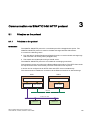
Communication via SIMATIC HMI HTTP protocol ................................................................................. 115
3.1
3.1.1
Principles on the protocol.......................................................................................................... 115
Principles on the protocol.......................................................................................................... 115
3.2
3.2.1
3.2.2
3.2.2.1
3.2.3
3.2.3.1
3.2.3.2
3.2.4
3.2.4.1
3.2.4.2
Configuring the communication driver ...................................................................................... 117
Permitted data types ................................................................................................................. 117
Installing the communication driver........................................................................................... 118
Installing the communication driver........................................................................................... 118
Configure HTTP server ............................................................................................................. 119
Configuring HTTP server functions........................................................................................... 119
Configuring tags in HTTP servers............................................................................................. 120
Configuring HTTP clients .......................................................................................................... 120
Configuring HTTP connections in the client.............................................................................. 120
Configuring tags in HTTP clients .............................................................................................. 122
3.3
3.3.1
3.3.2
Initiating an HTTP connection................................................................................................... 123
Setting the Internet Settings...................................................................................................... 123
Setting up an HTTPS connection.............................................................................................. 126
Communication via OPC........................................................................................................................ 129
4.1
4.1.1
4.1.1.1
4.1.1.2
4.1.1.3
4.1.2
OPC - OLE for process control ................................................................................................. 129
Basic principles ......................................................................................................................... 129
OPC........................................................................................................................................... 129
OPC over DCOM ...................................................................................................................... 130
OPC via XML ............................................................................................................................ 131
Using the HMI device ................................................................................................................ 132
4.2
4.2.1
4.2.2
Configuring OPC ....................................................................................................................... 134
Installing OPC ........................................................................................................................... 134
Configuring OPC server mode for the HMI ............................................................................... 135
WinCC flexible 2008 Communication Part 1
User's Manual, 07/2008, 6AV6691-1CA01-3AB0
Table of contents
5
4.2.2.1
4.2.3
4.2.3.1
4.2.3.2
4.2.3.3
4.2.3.4
4.2.4
Configuring OPC server mode for the HMI................................................................................135
Configure the HMI device as OPC client ...................................................................................136
Configure the HMI device as OPC client ...................................................................................136
Managing access to OPC XML Server ......................................................................................138
Configuring protocol parameters................................................................................................140
Configuring tag parameters .......................................................................................................140
Permitted data types (OPC).......................................................................................................143
4.3
4.3.1
4.3.1.1
4.3.1.2
4.3.1.3
Commissioning OPC..................................................................................................................144
DCOM ........................................................................................................................................144
DCOM settings...........................................................................................................................144
Starting the "dcomcnfg" program ...............................................................................................145
Configuring DCOM on the OPC DA server................................................................................146
Communication with SIMOTION controllers .......................................................................................... 147
5.1
6
7
Requirements for communication with SIMOTION....................................................................147
Communication with WinAC controllers ................................................................................................. 151
6.1
6.1.1
6.1.2
PC-based automation solution...................................................................................................151
Valid data types and user data areas ........................................................................................151
Requirements for communication with WinAC ..........................................................................151
6.2
6.2.1
6.2.2
6.2.3
Multi panel-based automation solution ......................................................................................152
WinAC MP basics ......................................................................................................................152
System requirements .................................................................................................................154
Valid data types and user data areas ........................................................................................154
Communication with SIMATIC S5 controllers ........................................................................................ 155
7.1
7.1.1
7.1.2
Communication with SIMATIC S5..............................................................................................155
Communications partner (SIMATIC S5) ....................................................................................155
Communication between the HMI and the PLC.........................................................................156
7.2
7.2.1
7.2.1.1
7.2.1.2
7.2.1.3
7.2.1.4
7.2.1.5
7.2.2
7.2.2.1
7.2.2.2
7.2.2.3
7.2.2.4
7.2.2.5
7.2.3
7.2.4
Configuring the communication driver for SIMATIC S5 .............................................................156
Communication over AS511 ......................................................................................................156
Requirements of communication ...............................................................................................156
Installing the communication driver............................................................................................157
Configuring the controller type and protocol ..............................................................................157
Configuring protocol parameters................................................................................................157
Permitted data types (SIMATIC S5 AS511)...............................................................................159
Communication over PROFIBUS DP ........................................................................................159
Requirements of communication ...............................................................................................159
Communication driver for HMI device........................................................................................160
Configuring the controller type and protocol ..............................................................................163
Configuring protocol parameters................................................................................................163
Permitted data types (SIMATIC S5 PROFIBUS DP) .................................................................165
Notes on avoiding errors............................................................................................................165
Optimizing the configuration ......................................................................................................166
7.3
7.3.1
7.3.1.1
7.3.1.2
7.3.1.3
7.3.1.4
7.3.1.5
7.3.1.6
7.3.1.7
7.3.1.8
User data areas .........................................................................................................................167
Area pointer................................................................................................................................167
General information on area pointers (SIMATIC S5).................................................................167
"Screen number" area pointer....................................................................................................169
"Date/time" area pointer.............................................................................................................170
"Date/time controller" area pointer .............................................................................................171
"Coordination" area pointer........................................................................................................172
"User version" area pointer ........................................................................................................173
"Job mailbox" area pointer .........................................................................................................173
"Data mailbox" area pointer .......................................................................................................176
WinCC flexible 2008 Communication Part 1
User's Manual, 07/2008, 6AV6691-1CA01-3AB0
11
Table of contents
8
12
7.3.2
7.3.2.1
7.3.2.2
7.3.2.3
7.3.2.4
7.3.3
7.3.4
Events, alarms, and acknowledgments .................................................................................... 183
General information on events, alarms, and acknowledgments ............................................... 183
Step 1: Creating tags or an array.............................................................................................. 184
Step 2: Configuring an alarm .................................................................................................... 185
Step 3: Configure the acknowledgment .................................................................................... 187
Trend request and trend transfer .............................................................................................. 189
LED mapping ............................................................................................................................ 191
7.4
7.4.1
Commissioning components ..................................................................................................... 192
Commissioning components ..................................................................................................... 192
7.5
7.5.1
7.5.2
7.5.3
Connecting cables for SIMATIC S5 .......................................................................................... 194
Connecting cable 6XV1 440-2A, TTY, for SIMATIC S5............................................................ 194
Connecting cable 6ES5 734-1BD20, TTY, for SIMATIC S5 ..................................................... 195
Connecting cable 6ES5 734-2BD20, TTY, for SIMATIC S5 ..................................................... 196
Communication with SIMATIC 500/505 controllers................................................................................ 197
8.1
8.1.1
8.1.2
Communication with SIMATIC 500/505 .................................................................................... 197
Communication partner (SIMATIC 500/505)............................................................................. 197
Communication between HMI device and controller (SIMATIC 500/505) ................................ 198
8.2
8.2.1
8.2.2
8.2.3
8.2.3.1
8.2.3.2
8.2.3.3
8.2.3.4
8.2.4
8.2.4.1
8.2.4.2
8.2.4.3
8.2.4.4
8.2.4.5
8.2.4.6
Configuring the communication driver SIMATIC 500/505......................................................... 199
Permitted data types (SIMATIC 500/505) ................................................................................. 199
Optimizing the configuration ..................................................................................................... 201
Communication driver for the NITP protocol............................................................................. 202
Requirements of communication .............................................................................................. 202
Installing the communication driver........................................................................................... 203
Configuring the controller type and protocol ............................................................................. 203
Configuring protocol parameters............................................................................................... 204
Communication driver for PROFIBUS DP ................................................................................ 205
Requirements of communication .............................................................................................. 205
Installing the communication driver........................................................................................... 205
Configuring the controller type and protocol ............................................................................. 206
Configuring protocol parameters............................................................................................... 206
Assigning parameter values for the PROFIBUS DP network based on the example of
COM PROFIBUS ...................................................................................................................... 208
Sample program for handling the DP protocol on the controller............................................... 209
8.3
8.3.1
8.3.2
8.3.3
8.3.3.1
8.3.3.2
8.3.3.3
8.3.3.4
8.3.3.5
8.3.3.6
8.3.3.7
8.3.3.8
8.3.4
8.3.4.1
8.3.4.2
8.3.4.3
8.3.4.4
User data areas......................................................................................................................... 210
Trend request and trend transfer .............................................................................................. 210
LED mapping ............................................................................................................................ 212
Area pointer............................................................................................................................... 213
General information on area pointers (SIMATIC 500/505) ....................................................... 213
"Screen number" area pointer................................................................................................... 215
"Date/time" area pointer ............................................................................................................ 216
"Date/time controller" area pointer ............................................................................................ 217
"Coordination" area pointer ....................................................................................................... 218
"Project ID" area pointer............................................................................................................ 219
"Job mailbox" area pointer ........................................................................................................ 219
"Data mailbox" area pointer ...................................................................................................... 222
Events, alarms, and acknowledgments .................................................................................... 229
General information on events, alarms, and acknowledgments ............................................... 229
Step 1: Creating tags or an array.............................................................................................. 230
Step 2: Configuring an alarm .................................................................................................... 231
Step 3: Configure the acknowledgment .................................................................................... 233
8.4
8.4.1
Commissioning components ..................................................................................................... 235
Commissioning components ..................................................................................................... 235
WinCC flexible 2008 Communication Part 1
User's Manual, 07/2008, 6AV6691-1CA01-3AB0
Table of contents
8.5
8.5.1
8.5.2
8.5.3
8.5.4
8.5.5
9
Connecting cables for SIMATIC 500/505 ..................................................................................237
Connecting cable PP1, RS-232, for SIMATIC 500/505 .............................................................237
Connecting cable 6XV1440-2K, RS-232, for SIMATIC 500/505 ...............................................238
Connecting cable 6XV1440-2L, RS-232, for SIMATIC 500/505................................................239
Connecting cable 6XV1440-1M, RS-422, for SIMATIC 505......................................................240
Connecting cable 6XV1440-2M, RS-422, for SIMATIC 500/505...............................................241
Appendix................................................................................................................................................ 243
9.1
System alarms ...........................................................................................................................243
9.2
Abbreviations .............................................................................................................................274
9.3
Glossary .....................................................................................................................................276
Index...................................................................................................................................................... 279
WinCC flexible 2008 Communication Part 1
User's Manual, 07/2008, 6AV6691-1CA01-3AB0
13
Table of contents
14
WinCC flexible 2008 Communication Part 1
User's Manual, 07/2008, 6AV6691-1CA01-3AB0
Working with connections
1.1
Basics
1.1.1
Communication basics
1
Introduction
The data exchange between two communication partners is known as communication.
The communication partners can be interconnected via direct cable connection or network.
Communication partners
A communication partner can be any node which is capable of communicating and
exchanging data with other nodes on the network. In the WinCC flexible environment, the
following nodes can be communication partners:
● Central modules and communication modules in the automation system
● can be HMI devices and communication processors in the PC.
Data transferred between the communication partners may serve different purposes:
● process control
● process data acquisition
● reporting states in a process
● process data logging
WinCC flexible 2008 Communication Part 1
User's Manual, 07/2008, 6AV6691-1CA01-3AB0
15
Working with connections
1.1 Basics
1.1.2
Principles of communication
Introduction
WinCC flexible controls communication between the HMI and the PLC by means of tags and
area pointers.
Communication using tags
In WinCC flexible, tags are centrally managed in the "Tag" editor. There are external and
internal tags. External tags are used for communication, and represent the image of defined
memory locations on the PLC. The HMI and the PLC both have read and write access to this
storage location. Those read and write operations may cyclic or event-triggered.
In your configuration, create tags that point to specific PLC addresses. The HMI reads the
value from the defined address, and then displays it. The operator may also enter values on
the HMI device which will be written to the relevant PLC address.
Communication using area pointers
Area pointers are used to exchange data of specific user data areas. Area pointers are
parameter fields. WinCC flexible receives from these parameter fields in runtime the
information about the location and size of data areas in the PLC. During communication, the
PLC and the HMI device alternately access those data areas for read and write operations.
Based on the evaluation of data stored in the data areas, the PLC and HMI device trigger
defined actions.
WinCC flexible uses the following area pointers:
● Control request
● Project ID
● Screen number
● Data record
● Date/time
● Date/time PLC
● Coordination
The availability of the various area pointers is determined by the HMI used.
Communication between WinCC flexible and automation systems
Industrial communication using WinCC flexible means that data are exchanged using tags
and area pointers. To acquire the data, the HMI sends request messages to the automation
system using a communication driver. The automation system (AS) returns the requested
data to the HMI in a response frame.
16
WinCC flexible 2008 Communication Part 1
User's Manual, 07/2008, 6AV6691-1CA01-3AB0
Working with connections
1.1 Basics
Communication drivers
A communication driver is a software component that develops a connection between an
automation system and an HMI device. The communication driver hence enables the tags in
WinCC flexible to be supplied with process values. WinCC flexible supports the
interconnection of different automation systems with various communication drivers.
Users can select the interface, the profile and the transmission speed for each specific
communication partner.
Communication between HMIs
The SIMATIC HMI HTTP Protocol is available for the communication between HMIs. This
protocol is a component of the "Sm@rtAccess" option. The protocol can be used on PCs
with WinCC flexible Runtime and on Panels as of the 270 series. For detailed information,
refer to the SIMATIC HMI HTTP Protocol documentation.
Communication via uniform and manufacturer-independent interface
WinCC flexible provides a uniform and manufacturer-independent software interface using
OPC (OLE for Process Control). This interface allows a standardized data exchange
between applications for industry, office, and production. For detailed information, refer to
the OPC documentation.
WinCC flexible 2008 Communication Part 1
User's Manual, 07/2008, 6AV6691-1CA01-3AB0
17
Working with connections
1.2 Elements and basic settings
1.2
Elements and basic settings
1.2.1
Connections Editor
Introduction
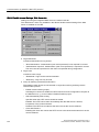
In the "Connections" editor, you create and configure connections.
Open
Select "Connections" from the project view, and then open the shortcut menu. Select "New
connection" from in this shortcut menu. The new connection will be created and opened in
the work area.
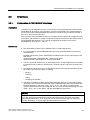
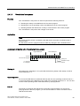
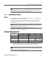
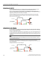
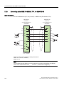
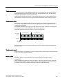
Structure
3URMHFWYLHZ
:RUNDUHD
2EMHFWYLHZ
3DUDPHWHUV
$UHDSRLQWHU
Menu bar
The menu bar contains all commands required for operating WinCC flexible. Available key
combinations are indicated next to the menu command.
Toolbars
The toolbars contain the most frequently used buttons.
Select "View > Toolbars" to show or hide the specific toolbars. The
be used to show or hide specific buttons of this toolbar.
18
button of a toolbar can
WinCC flexible 2008 Communication Part 1
User's Manual, 07/2008, 6AV6691-1CA01-3AB0
Working with connections
1.2 Elements and basic settings
Work area
All connections are visualized in the work area in tabular format. You select the
communication drivers from the table cells, and edit the relevant connection properties. To
sort the table by its column entries, simply click the column header.
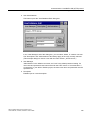
"Parameters" tab
Using the "Parameters" tab you can configure the settings for the communication drivers
selected in the table. Select the settings for the HMI, the network and for the PLC.
"Area pointer" tab
Using the "Area pointers" tab you can configure the area pointers of the connections.
1.2.2
Parameters for connections
Introduction
Select the "Parameters" tab of the "Connections" editor to configure the properties of a
connection between the HMI and the communication partner.
Structure
The communication partners are visualized schematically on the "Parameters" tab. This tab
provides the "HMI device", "Network" and "PLC" areas where you can declare the
parameters of the relevant interface used.
The system sets default parameters. Always ensure consistency on the network whenever
you edit parameters. For detailed information on configurable parameters, refer to the
description of the supported protocols.
WinCC flexible 2008 Communication Part 1
User's Manual, 07/2008, 6AV6691-1CA01-3AB0
19
Working with connections
1.2 Elements and basic settings
1.2.3
Area pointers for connections
Introduction
Using the "Area pointer" tab of the "Connections" editor, you can configure the usage of the
available area pointers.
Structure
The "Area pointer" tab contains two tables of area pointers. The "For all connections" table
contains those area pointers which are created only once in the project and can be used for
only one connection.
The "For each connection" table contains the area pointers you can set separately for each
available connection.
The availability of the various area pointers is determined by the HMI device used. For
detailed information on area pointers and their configuration, refer to the description of the
supported protocols.
20
WinCC flexible 2008 Communication Part 1
User's Manual, 07/2008, 6AV6691-1CA01-3AB0
Working with connections
1.3 Configuring the connection
1.3
Configuring the connection
Introduction
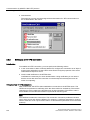
You create a new connection using the Connections editor.
Requirements
A project is open.
Procedure
1. In the project view, open the "Communication" group.
2. Select "New connection" from the "Connections" shortcut menu.
The "Connections" editor opens and shows a new connection.
3. Rename the connection in the "Name" column as required.
4. From the "Communication driver" column, select a communication driver that is suitable
for the PLC being used.
Only those drivers that are supported by the selected HMI device will be displayed.
5. The system automatically sets suitable values for the communication partner in the
"Parameters" tab.
6. Check the parameters, and edit these as required.
7. Save the project.
WinCC flexible 2008 Communication Part 1
User's Manual, 07/2008, 6AV6691-1CA01-3AB0
21
Working with connections
1.4 Connections and protocols
Alternative procedure
Select "Insert > New item > Connection" from the menu bar. The "Connections" editor opens
and shows a new connection. Edit the connection as described in steps 2 through 7.
You can drag-and-drop existing connections directly from HMI_1 or via an interim station in
the library to HMI_2. The output view shows the following information: "The interface used for
the connection has been adapted to the device". A device change is performed for this
connection. The system does not verify whether or not the HMI_2 supports the
communications driver.
Open the "Connections" editor on HMI_2 to check the connections. Faulty entries are
marked in orange.
Result
A new connection was created. The connection parameters are configured.
1.4
Connections and protocols
HMI functionality
The HMI is used to read, save and record alarms and tags. In addition, the HMI can be used
to intervene in the process.
CAUTION
Ethernet communication
In Ethernet-based communication, such as PROFINET IO, HTTP, Sm@rtAccess,
Sm@rtService and OPC, it is the end user who is responsible for the security of his data
network. The proper functioning of the device cannot be guaranteed in all circumstances;
targeted attacks, for example, can lead to an overloading of the device.
Data exchange
The prerequisite for the operating and monitoring functions is the connection of the HMI
device to a PLC. Data exchange between the HMI and the PLC is controlled by a
connection-specific protocol. Each connection requires a separate protocol.
Criteria for selecting the connection
Criteria for selecting the connection between the HMI and the PLC are, for example:
● PLC type
● CPU in the PLC
● HMI device type
● Number of HMI devices per PLC
● Structure and any bus systems of an existing plant
● Amount of components additionally required
22
WinCC flexible 2008 Communication Part 1
User's Manual, 07/2008, 6AV6691-1CA01-3AB0
Working with connections
1.4 Connections and protocols
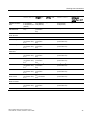
Protocols
Protocols are available for the following PLCs:
PLC
Protocol
SIMATIC S7
•
•
•
•
PPI
MPI 1)
PROFIBUS DP
TCP/IP (Ethernet)
SIMATIC S5
•
•
AS 511
PROFIBUS DP
SIMATIC 500/505
•
•
NITP
PROFIBUS DP
SIMATIC HMI HTTP Protocol
•
HTTP/HTTPS (Ethernet)
SIMOTION
•
•
•
MPI
PROFIBUS DP
TCP/IP (Ethernet)
OPC
•
DCOM
Allen-Bradley
PLC series SLC500, SLC501, SLC502, SLC503, SLC504,
SLC505, MicroLogix and PLC5/11, PLC5/20, PLC5/30, PLC5/40,
PLC5/60, PLC5/80
• DF1 2)
• DH+ via KF2 module 3)
• DH485 via KF3 module 4)
• DH485 4)
PLC series ControlLogix 5500 (with 1756-ENBT) and
CompactLogix 5300 (1769-L32E and 1769-L35E)
• Ethernet
GE Fanuc Automation
SPS series 90–30, 90–70, VersaMax Micro
• SNP
LG Industrial Systems (Lucky
Goldstar) / IMO
PLC series GLOFA GM (GM4, GM6 and GM7) / Series G4, G6
and G7
• Dedicated communication
Mitsubishi Electric
PLC series MELSEC FX and MELSEC FX0
• FX (Mitsubishi PG)
Mitsubishi Electric
PLC series MELSEC FX0, FX1n, FX2n, AnA, AnN, AnS, AnU,
QnA and QnAS
• Protocol 4
OMRON
PLC series SYSMAC C, SYSMAC CV, SYSMAC CS1, SYSMAC
alpha, CJ and CP
• Hostlink/Multilink (SYSMAC Way)
Modicon
(Schneider Automation)
PLC series Modicon 984, TSX Quantum and TSX Compact
• Modbus RTU
SPS series Quantum, Momentum, Premium and Micro
SPS series Compact and 984 via Ethernet bridge
• Modbus TCP/IP (Ethernet)
WinCC flexible 2008 Communication Part 1
User's Manual, 07/2008, 6AV6691-1CA01-3AB0
23
Working with connections
1.5 Device-based dependency
PLC
Protocol
Telemecanique
PLC series TSX 7 with P47 411, TSX 7 with P47/67/87/107 420,
TSX 7 with P47/67/87/107 425, module TSX SCM 21.6 with the
specified TSX 7 CPUs, TSX 17 with module SCG 1161, TSX 37
(Micro), TSX 57 (Premium)
• Uni-Telway
1)
Not possible when connected to S7-212.
2)
Applies to controllers SLC503, SLC504, SLC505, PLC5, MicroLogix
3)
Applies to controllers SLC504, PLC5 over DF1
4)
Applies to controllers SLC500 to SLC 505 and MicroLogix
1.5
Device-based dependency
1.5.1
Device-dependency of the protocols
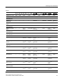
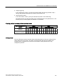
Availability of the communication protocols
Communication between the HMI and the PLC is controlled using a network-specific
protocol. The following tables show the availability of the communication protocols on the
HMI devices.
Overview
Micro Panels
OP 73micro 1)
TP 170micro 1)
TP 177micro 1)
Yes
Yes
Yes
Yes
Yes
Yes
Yes
Yes
Yes
SIMATIC S7 - PROFINET
No
No
No
SIMATIC S5 - AS511
No
No
No
SIMATIC S5 - PROFIBUS DP
No
No
No
SIMATIC 500/505 - NITP
No
No
No
SIMATIC 500/505 PROFIBUS DP
No
No
No
SIMATIC HMI HTTP Protocol
No
No
No
OPC
No
No
No
SIMOTION
No
No
No
Allen-Bradley DF1
No
No
No
Allen-Bradley DH 485
No
No
No
SIMATIC S7 - PPI 1)
SIMATIC S7 - MPI 1)
SIMATIC S7 - PROFIBUS-DP
24
1)
WinCC flexible 2008 Communication Part 1
User's Manual, 07/2008, 6AV6691-1CA01-3AB0
Working with connections
1.5 Device-based dependency
OP 73micro 1)
TP 170micro 1)
TP 177micro 1)
Allen-Bradley Ethernet IP
No
No
No
GE Fanuc
No
No
No
LG GLOFA-GM
No
No
No
Mitsubishi FX
No
No
No
Mitsubishi P4
No
No
No
Modicon Modbus RTU
No
No
No
Modicon Modbus TCP/IP
No
No
No
Omron
No
No
No
Telemecanique
No
No
No
Mobile Panels
Mobile Panel
170
Mobile Panel
177 DP
Mobile Panel
177 PN
Mobile Panel
277 4)
Mobile Panel
277 IWLAN
Mobile Panel
277F IWLAN
SIMATIC S7 - PPI 1)
Yes
Yes
No
Yes
No
SIMATIC S7 - MPI
Yes
Yes
No
Yes
No
SIMATIC S7 PROFIBUS DP
Yes
Yes
No
Yes
No
SIMATIC S7 - PROFINET
No
No
Yes
Yes
Yes
SIMATIC S5 - AS511
Yes
No
No
yes 3)
No
SIMATIC S5 PROFIBUS DP
Yes
Yes
No
Yes
No
SIMATIC 500/505 - NITP
Yes
Yes
No
Yes
No
SIMATIC 500/505 PROFIBUS DP
Yes
Yes
No
Yes
No
SIMATIC HMI
HTTP Protocol
No
No
Yes
Yes
Yes
OPC
No
No
No
Yes
Yes
SIMOTION
Yes
Yes
Allen-Bradley DF1
Yes
Allen-Bradley DH 485
Allen-Bradley Ethernet IP
GE Fanuc
Yes
Yes 7) 8)
LG GLOFA-GM
Yes
Yes
7) 8)
Mitsubishi FX
Yes
Yes
7) 8)
Mitsubishi P4
Yes
Yes 7) 8)
Modicon Modbus RTU
Yes
Yes 7) 8)
No
Modicon Modbus TCP/IP
No
No
Yes
Omron
Telemecanique
Yes
Yes
Yes
7) 8)
No
Yes
Yes
7) 8)
No
No
No
Yes
No
Yes
7) 8)
No
Yes
7) 8)
No
Yes 7) 8)
Yes 7)
No
Yes 7) 8)
No
No
Yes
7) 8)
No
No
Yes
7) 8)
No
No
Yes 7) 8)
No
Yes 7) 8)
No
Yes
7) 8)
No
7) 8)
No
No
7)
7)
Yes
Yes
7) 8)
No
Yes
Yes
Yes 7) 8)
No
Yes 7) 8)
WinCC flexible 2008 Communication Part 1
User's Manual, 07/2008, 6AV6691-1CA01-3AB0
25
Working with connections
1.5 Device-based dependency
Basic Panels
KTP400
Basic PN
KTP600 Basic
DP
KTP600 Basic
PN 11)
KTP1000
Basic DP
KTP1000
Basic PN
TP1500 Basic
PN
SIMATIC S7 - PPI 1) No
Yes
No
Yes
No
No
SIMATIC S7 - MPI
No
Yes
No
Yes
No
No
SIMATIC S7 PROFIBUS DP
No
Yes
No
Yes
No
No
SIMATIC S7 PROFINET
Yes
No
Yes
No
Yes
Yes
SIMATIC S5 AS511
No
No
No
No
No
No
SIMATIC S5 PROFIBUS DP
No
No
No
No
No
No
SIMATIC 500/505 NITP
No
No
No
No
No
No
SIMATIC 500/505 PROFIBUS DP
No
No
No
No
No
No
SIMATIC HMI
HTTP Protocol
No
No
No
No
No
No
OPC
No
No
No
No
No
No
SIMOTION
No
No
No
No
No
No
Allen-Bradley DF1
No
Yes 10)
No
Yes 10)
No
No
Allen-Bradley
DH 485
No
No
No
No
No
No
Allen-Bradley
Ethernet IP
No
No
No
No
No
No
GE Fanuc
No
No
No
No
No
No
LG GLOFA-GM
No
No
No
No
No
No
Mitsubishi FX
No
No
No
No
No
No
Mitsubishi P4
No
No
No
No
No
No
Modicon
Modbus RTU
No
Yes
No
Yes
No
No
Modicon
Modbus TCP/IP
No
No
No
No
No
No
Omron
No
No
No
No
No
No
Telemecanique
No
No
No
No
No
No
5)
5)
Panels
OP 73
OP 77A
OP 77B 9)
SIMATIC S7 - PPI 1)
Yes
Yes
Yes 8)
Yes
Yes
Yes
Yes
Yes
Yes
SIMATIC S7 - MPI
Yes
Yes
Yes
Yes
Yes
Yes
Yes
Yes
Yes
SIMATIC S7 PROFIBUS DP
Yes
Yes
Yes
Yes
Yes
Yes
Yes
Yes
Yes
SIMATIC S7 PROFINET
No
No
No
No
Yes
No
Yes
Yes
Yes
26
TP 170A 9)
TP 170B
OP 170B
TP 177A TP 177B 9) TP 270
OP 177B 9) OP 270
6)
TP 277 9)
OP 277 9)
WinCC flexible 2008 Communication Part 1
User's Manual, 07/2008, 6AV6691-1CA01-3AB0
Working with connections
1.5 Device-based dependency
OP 73
OP 77A
OP 77B 9)
TP 170A 9)
TP 170B
OP 170B
TP 177A TP 177B 9) TP 270
OP 177B 9) OP 270
TP 277 9)
OP 277 9)
SIMATIC S5 AS511
No
No
Yes
Yes
Yes
No
No
Yes
No
SIMATIC S5 PROFIBUS DP
No
No
Yes
No
Yes
No
Yes
Yes
Yes
SIMATIC 500/505 NITP
No
No
Yes
Yes
Yes
No
Yes
Yes
Yes
SIMATIC 500/505 PROFIBUS DP
No
No
Yes
No
Yes
No
Yes
Yes
Yes
SIMATIC HMI
HTTP Protocol
No
No
No
No
No
No
Yes 6)
Yes
Yes
OPC
No
No
No
No
No
No
No
No
No
SIMOTION
No
No
Yes
No
Yes
Yes
Allen-Bradley DF1
No
Yes
Yes
Yes
Yes
Yes 7) 9)
Allen-Bradley
DH 485
No
No
Yes 9)
Yes 9)
Yes
No
Yes
7) 9)
Yes
Yes
7) 9)
Allen-Bradley
Ethernet IP
No
No
No
No
No
No
Yes
6) 7)
No
Yes
7)
GE Fanuc
No
No
Yes 9)
Yes 9)
Yes
No
Yes
7) 9)
LG GLOFA-GM
No
No
Yes
9)
Yes
9)
Yes
No
Mitsubishi FX
No
No
Yes
9)
Yes
9)
Yes
Mitsubishi P4
No
No
Yes 9)
Yes 9)
Modicon
Modbus RTU
No
Yes 5)
Yes 9)
Modicon
Modbus TCP/IP
No
No
No
Omron
No
No
Yes 9)
Telemecanique
No
No
Yes
No
10)
Yes
WinCC flexible 2008 Communication Part 1
User's Manual, 07/2008, 6AV6691-1CA01-3AB0
No
9)
9)
Yes
9)
Yes
10)
Yes
7) 9) 10)
10)
Yes
Yes
Yes
7) 9)
Yes
Yes
No
Yes
7) 9)
Yes
Yes 7) 9)
Yes
No
Yes 7) 9)
Yes
Yes 7) 9)
Yes 9)
Yes
Yes 5)
Yes 5) 7) 9)
Yes
Yes 5) 7) 9)
No
No
No
Yes 6) 7)
Yes
Yes 7)
Yes 9)
Yes
No
Yes 7) 9)
Yes
Yes 7) 9)
Yes
Yes
No
Yes
Yes
Yes 7) 9)
9)
7) 9)
7) 9)
7) 9)
27
Working with connections
1.5 Device-based dependency
Multi Panels
MP 177 9)
MP 270B
MP 277 9)
MP 370
MP377 9)
SIMATIC S7 - PPI 1)
Yes
Yes
Yes
Yes
Yes
SIMATIC S7 - MPI
Yes
Yes
Yes
Yes
Yes
SIMATIC S7 - PROFIBUS DP
Yes
Yes
Yes
Yes
Yes
SIMATIC S7 - PROFINET
Yes
Yes
Yes
Yes
Yes
SIMATIC S5 - AS511
No
Yes
No
Yes
No
SIMATIC S5 - PROFIBUS DP
Yes
Yes
Yes
Yes
Yes
SIMATIC 500/505 - NITP
Yes
Yes
Yes
Yes
Yes
SIMATIC 500/505 PROFIBUS DP
Yes
Yes
Yes
Yes
Yes
SIMATIC HMI HTTP Protocol
Yes
Yes
Yes
Yes
Yes
OPC
No
Yes
Yes
Yes
Yes
SIMOTION
No
Yes
Yes
Yes
Yes
Allen-Bradley DF1
Yes 7) 9) 10)
Yes
Yes 7) 9) 10)
Yes
Yes 7) 9) 10)
Allen-Bradley DH 485
Yes
7) 9)
Yes
Yes
7) 9)
Yes
Yes 7) 9)
Allen-Bradley Ethernet IP
Yes 7) 9)
Yes
Yes 7) 9)
Yes
Yes 7) 9)
GE Fanuc
Yes 7) 9)
Yes
Yes 7) 9)
Yes
Yes 7) 9)
LG GLOFA-GM
Yes 7) 9)
Yes
Yes 7) 9)
Yes
Yes 7) 9)
Mitsubishi FX
Yes
7) 9)
Yes
Yes
7) 9)
Yes
Yes 7) 9)
Mitsubishi P4
Yes 7) 9)
Yes
Yes 7) 9)
Yes
Yes 7) 9)
Modicon Modbus RTU
Yes 5) 7) 9)
Yes
Yes 5) 7) 9)
Yes
Yes 5) 7) 9)
Modicon Modbus TCP/IP
Yes 7) 9)
Yes
Yes 7) 9)
Yes
Yes 7) 9)
Omron
Yes
7) 9)
Yes
Yes
7) 9)
Yes
Yes 7) 9)
Telemecanique
Yes 7) 9)
Yes
Yes 7) 9)
Yes
Yes 7) 9)
WinCC flexible Runtime
WinCC flexible Runtime
SIMATIC S7 - PPI
1)
Yes
SIMATIC S7 - MPI
Yes
SIMATIC S7 - PROFIBUS DP
Yes
SIMATIC S7 - PROFINET
Yes
SIMATIC S5 - AS511
Yes
SIMATIC S5 - PROFIBUS DP
Yes
SIMATIC 500/505 - NITP
Yes
SIMATIC 500/505 - PROFIBUS DP
Yes
SIMATIC HMI HTTP Protocol
Yes
OPC
Yes
SIMOTION
Yes
Allen-Bradley DF1
Yes
Allen-Bradley DH 485
Yes
Allen-Bradley Ethernet IP
Yes
28
WinCC flexible 2008 Communication Part 1
User's Manual, 07/2008, 6AV6691-1CA01-3AB0
Working with connections
1.5 Device-based dependency
WinCC flexible Runtime
GE Fanuc
Yes
LG GLOFA-GM
Yes
Mitsubishi FX
Yes
Mitsubishi P4
Yes
Modicon Modbus RTU
Yes
Modicon Modbus TCP/IP
Yes
Omron
Yes
Telemecanique
No
1.5.2
1)
only with SIMATIC S7-200
2)
only MP 270B
3)
only with RS 232/TTY adapter 6ES5 734-1BD20 (option)
4)
Depends on which connection box is used
5)
only with converter RS 422-RS 232 6AV6 671-8XE00-0AX0 (option)
6)
Applies only to TP 177B PN/DP and OP 177B PN/DP.
7)
PROFINET IO Enabled must be deactivated
8)
Up to four SIMATIC S7-200 connections via PPI network
9)
For a series communication in the menu "File > Transfer > Options", clear "Remote Control"
from "Channel 1".
10)
Direct communication with PLC5 or KF2 module, otherwise approved only with converter RS
422-RS232 6AV6 671-8XE00-0AX0 (option)
11)
KTP600 Basic PN color and KTP600 Basic PN mono.
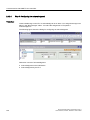
Device-based dependency of the interfaces
Introduction
The PLC and HMI device use a communication connection for data exchange. You must
ensure the interfaces are in concordance. Among others, the following parameters must be
noted:
● The PLC and communication drivers must be in concordance
● The HMI device must support the required communication protocol
● Using the interface supported by the HMI device
The "Connections" editor is used to configure the parameters for the communication drivers.
Supported interfaces
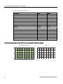
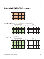
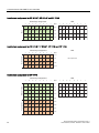
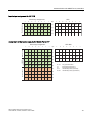
The following tables show the hardware interfaces that are to be used on the HMI devices.
WinCC flexible 2008 Communication Part 1
User's Manual, 07/2008, 6AV6691-1CA01-3AB0
29
Working with connections
1.5 Device-based dependency
Overview
Micro Panels
OP 73micro 1)
TP 170micro 1)
TP 177micro 1)
SIMATIC S7 – PPI 1)
IF1B
IF1B
IF1B
SIMATIC S7 - MPI
IF1B
IF1B
IF1B
SIMATIC S7 - PROFIBUS DP 1)
IF1B
IF1B
IF1B
SIMATIC S7 - PROFINET
—
—
—
SIMATIC S5 - AS511
—
—
—
SIMATIC S5 - PROFIBUS DP
—
—
—
SIMATIC 500/505 - NITP
—
—
—
SIMATIC 500/505 PROFIBUS DP
—
—
—
SIMATIC HMI HTTP Protocol
—
—
—
OPC
—
—
—
Allen-Bradley DF1
—
—
—
Allen-Bradley DH 485
—
—
—
Allen-Bradley Ethernet IP
—
—
—
GE Fanuc
—
—
—
LG GLOFA-GM
—
—
—
Mitsubishi FX
—
—
—
Mitsubishi P4
—
—
—
Modicon Modbus RTU
—
—
—
Modicon Modbus TCP/IP
—
—
—
Omron
—
—
—
Telemecanique
—
—
—
1)
Mobile Panels
Mobile Panel 170 Mobile Panel
177 DP 8)
Mobile Panel
177 PN
Mobile Panel 277 4) 8)
Mobile Panel
277 IWLAN
Mobile Panel 277F
IWLAN
SIMATIC S7 - PPI 1)
IF1B
IF1B
—
IF1B
—
SIMATIC S7 - MPI
IF1B
IF1B
—
IF1B
—
SIMATIC S7 PROFIBUS DP
IF1B
IF1B
—
IF1B
—
SIMATIC S7 PROFINET
—
—
Ethernet
Ethernet
Ethernet/Wireless
SIMATIC S5 - AS511
IF1A (connection
box) 3)
—
—
—
—
SIMATIC S5 PROFIBUS DP
IF1A (connection
box)
IF1B
—
IF1A (connection box) —
30
WinCC flexible 2008 Communication Part 1
User's Manual, 07/2008, 6AV6691-1CA01-3AB0
Working with connections
1.5 Device-based dependency
Mobile Panel 170 Mobile Panel
177 DP 8)
Mobile Panel
177 PN
Mobile Panel 277 4) 8)
Mobile Panel
277 IWLAN
Mobile Panel 277F
IWLAN
SIMATIC 500/505 NITP
IF1A (RS232)
IF1A (RS232)
IF1B (RS422) IF2 IF1B (RS422)
(RS232)
—
IF1A (RS232)
IF1B (RS422)
—
SIMATIC 500/505 PROFIBUS DP
IF1B (connection
box)
IF1B
(connection
box)
—
IF1B (connection box) —
SIMATIC HMI
HTTP Protocol
—
—
Ethernet
Ethernet
Ethernet/Wireless
OPC
—
—
—
—
OPC
Allen-Bradley DF1
IF1A 8), IF1B 8)9) —
IF1A, IF1B 9)
(connection box), (connection
IF2 8)
box)
IF1A 8), IF1B 8)9)
(connection box)
—
Allen-Bradley DH 485
IF1A, IF1B
IF1A 8), IF1B 8)
(connection box), (connection
IF2 8)
box)
—
IF1A 8), IF1B 8)
(connection box)
—
Allen-Bradley
Ethernet IP
—
Ethernet
Ethernet
Ethernet/Wireless
GE Fanuc
IF1A, IF1B
IF1A 8), IF1B 8)
(connection box), (connection
IF2 8)
box)
—
IF1A 8), IF1B 8)
(connection box)
—
LG GLOFA-GM
IF1A, IF1B
IF1A 8), IF1B 8)
(connection box), (connection
IF2 8)
box)
—
IF1A 8), IF1B 8)
(connection box)
—
Mitsubishi FX
IF1A, IF1B
IF1A 8), IF1B 8)
(connection box), (connection
IF2 8)
box)
—
IF1A 8), IF1B 8)
(connection box)
—
Mitsubishi P4
IF1A 8), IF1B 8)
IF1A, IF1B
(connection box), (connection
IF2 8)
box)
—
IF1A 8), IF1B 8)
(connection box)
—
Modicon
Modbus RTU
IF1A, IF1B 12)
IF1A 8), IF1B
—
(connection box), 8)12) (connection
IF2 8)
box)
IF1A 8), IF1B 8)12)
(connection box)
—
Modicon
Modbus TCP/IP
—
Ethernet
Ethernet
—
Omron
IF1A, IF1B
IF1A 8), IF1B 8)
(connection box), (connection
IF2 8)
box)
—
IF1A 8), IF1B 8)
(connection box)
—
Telemecanique
IF1B
—
IF1B 8)
—
WinCC flexible 2008 Communication Part 1
User's Manual, 07/2008, 6AV6691-1CA01-3AB0
---
—
IF1B 8)
31
Working with connections
1.5 Device-based dependency
Basic Panels
KTP400 Basic
PN
KTP600 Basic
DP
KTP600 Basic
PN
KTP1000
Basic DP
KTP1000
Basic PN
TP1500 Basic
PN
—
IF1B
—
IF1B
—
—
SIMATIC S7 - MPI —
IF1B
—
IF1B
—
—
SIMATIC S7 PROFIBUS DP
—
IF1B
—
IF1B
—
—
SIMATIC S7 PROFINET
Ethernet
—
Ethernet
—
Ethernet
Ethernet
SIMATIC S5 AS511
—
—
—
—
—
—
SIMATIC S5 PROFIBUS DP
—
—
—
—
—
—
SIMATIC 500/505
- NITP
—
—
—
—
—
—
SIMATIC 500/505
- PROFIBUS DP
—
—
—
—
—
—
SIMATIC HMI
HTTP Protocol
—
—
—
—
—
—
OPC
—
SIMATIC S7 PPI 1)
—
—
—
—
—
Allen-Bradley DF1 —
IF1B 11)
—
IF1B 11)
—
—
Allen-Bradley
DH 485
—
—
—
—
—
—
Allen-Bradley
Ethernet IP
—
—
—
—
—
—
GE Fanuc
—
—
—
—
—
—
LG GLOFA-GM
—
—
—
—
—
—
Mitsubishi FX
—
—
—
—
—
—
Mitsubishi P4
—
—
—
—
—
—
Modicon
Modbus RTU
—
IF1B
—
IF1B
—
—
Modicon
Modbus TCP/IP
—
—
—
—
—
—
Omron
—
—
—
—
—
—
Telemecanique
—
—
—
—
—
—
32
5)
5)
WinCC flexible 2008 Communication Part 1
User's Manual, 07/2008, 6AV6691-1CA01-3AB0
Working with connections
1.5 Device-based dependency
Panels
OP 73 OP 77A OP 77B 8) TP 170A 8) TP 170B TP 177A TP 177B 8) TP 270
OP 170B
OP 177B 8) OP 270
TP 277 8)
OP 277 8)
SIMATIC S7 - PPI 1) IF1B
IF1B
IF1B
IF1B
IF1B
IF1B
IF1B
IF1B
IF1B
SIMATIC S7 - MPI
IF1B
IF1B
IF1B
IF1B
IF1B
IF1B
IF1B
IF1B
IF1B
SIMATIC S7 PROFIBUS DP
IF1B
IF1B
IF1B
IF1B
IF1B
IF1B
IF1B
IF1B
IF1B
SIMATIC S7 PROFINET
—
—
—
—
Ethernet
—
Ethernet 6)
Ethernet
Ethernet
SIMATIC S5 AS511
—
—
IF1A
IF1A
IF1A, IF2 —
—
IF1A, IF2
—
SIMATIC S5 PROFIBUS DP
—
—
IF1B
—
IF1B
—
IF1B
IF1B
IF1B
SIMATIC 500/505 NITP
—
—
IF1A,
IF1B
IF1A, IF1B IF1A,
—
IF1B, IF2
IF1B
IF1A,
IF1B, IF2
IF1B
SIMATIC 500/505 PROFIBUS DP
—
—
IF1B
—
IF1B
—
IF1B
IF1B
IF1B
SIMATIC HMI
HTTP Protocol
—
—
—
—
—
—
Ethernet 6)
Ethernet
Ethernet
OPC
—
—
—
—
—
—
—
Allen-Bradley DF1
—
IF1B
IF1B
IF1A,
IF1B 11),
IF2 8)
IF1B 8)
Allen-Bradley
DH 485
—
—
IF1A,
IF1B, IF2
IF1B 8)
Allen-Bradley
Ethernet IP
—
—
Ethernet
GE Fanuc
—
IF1A,
IF1B, IF2
IF1B 8)
IF1A,
IF1B, IF2
IF1B 8)
IF1A,
IF1B, IF2
IF1B 8)
IF1A,
IF1B, IF2
IF1B 8)
LG GLOFA-GM
Mitsubishi FX
Mitsubishi P4
—
—
—
—
—
IF1A
IF1B 8)9)
IF1A
IF1B 8)9)
IF1A,
IF1B 9),
IF2 8)
IF1A 8),
IF1B 8)
IF1A 8),
IF1B 8)
—
IF1A,
IF1B, IF2
IF1B 8)
—
—
—
—
Ethernet
—
IF1A 8),
IF1B 8)
IF1A 8),
IF1B 8)
IF1A,
—
IF1B, IF2
IF1B 8)
—
IF1A 8),
IF1B 8)
IF1A 8),
IF1B 8)
—
IF1A,
IF1B, IF2
IF1B 8)
—
8),
8),
IF1A,
—
IF1B, IF2
IF1B
IF1A,
—
IF1B, IF2
IF1B 8)
11)
—
8),
8),
IF1A
IF1B 8)
IF1A
IF1B 8)
IF1A 8),
IF1B 8)
IF1A 8),
IF1B 8)
6)
11)
IF1B
8) 11)
8)
—
8)
8)
8)
8)
8)
8)
8)
8)
Modicon
Modbus RTU
—
IF1B 5)
IF1A 8),
IF1A 8),
IF1B 5)8)12) IF1B 5)8)12)
IF1A,
IF1B 5)
IF1B 5) 12)
IF2 8)
IF1B 5)
Modicon
Modbus TCP/IP
—
—
—
—
—
Ethernet
Omron
—
—
IF1A 8),
IF1B 8)
IF1A 8),
IF1B 8)
IF1A,
—
IF1B, IF2
IF1B 8)
IF1B 8)
IF1B 8)
IF1B
IF1B 8)
Telemecanique
—
—
WinCC flexible 2008 Communication Part 1
User's Manual, 07/2008, 6AV6691-1CA01-3AB0
8)
—
11)
8)
6)
8)
—
6)
IF1A,
IF1B 5) 8)
IF1B 5) 12),
IF2 8)
8)
6)
Ethernet
Ethernet
IF1A,
IF1B, IF2
IF1B 8)
IF1B
IF1B 8)
8)
33
Working with connections
1.5 Device-based dependency
Multi Panels
MP 177 8)
MP 270B
MP 277 8)
MP 370
MP 377 8)
SIMATIC S7 - PPI 1)
IF1B
IF1B
IF1B
IF1B
IF1B
SIMATIC S7 - MPI
IF1B
IF1B
IF1B
IF1B
IF1B
SIMATIC S7 PROFIBUS DP
IF1B
IF1B
IF1B
IF1B
IF1B
SIMATIC S7 PROFINET
Ethernet
Ethernet
Ethernet
Ethernet
Ethernet
SIMATIC S5 - AS511
-
IF1A, IF2
-
IF1A, IF2
-
SIMATIC S5 PROFIBUS DP
IF1B
IF1B
IF1B
IF1B
IF1B
SIMATIC 500/505 NITP
IF1B
IF1A, IF1B, IF2
IF1B
IF1A, IF1B, IF2
IF1B
SIMATIC 500/505 PROFIBUS DP
IF1B
IF1B
IF1B
IF1B
IF1B
SIMATIC HMI
HTTP Protocol
Ethernet
Ethernet
Ethernet
Ethernet
Ethernet
OPC
-
OPC
OPC
OPC
OPC
Allen-Bradley DF1
IF1B 8) 11)
IF1A, IF1B 9), IF2 8)
IF1B 8) 11)
IF1A, IF1B 9), IF2 8)
IF1B 8) 11)
Allen-Bradley DH 485
IF1B
IF1A, IF1B, IF2
IF1B
IF1A, IF1B, IF2
IF1B 8)
Allen-Bradley
Ethernet IP
Ethernet
Ethernet
GE Fanuc
IF1B 8)
LG GLOFA-GM
IF1B
Mitsubishi FX
IF1B 8)
IF1A, IF1B, IF2 8)
Mitsubishi P4
IF1B 8)
IF1A, IF1B, IF2 8)
Modicon
Modbus RTU
IF1B 5) 8)
Modicon
Modbus TCP/IP
8)
8)
8)
8)
Ethernet
Ethernet
IF1A, IF1B, IF2 8)
IF1B 8)
IF1A, IF1B, IF2 8)
IF1B 8)
IF1A, IF1B, IF2
IF1B
IF1A, IF1B, IF2
8)
IF1B 8)
IF1B 8)
IF1A, IF1B, IF2 8)
IF1B 8)
IF1B 8)
IF1A, IF1B, IF2 8)
IF1B 8)
IF1A, IF1B 12), IF2 8) IF1B 5) 8)
IF1A, IF1B 12), IF2 8)
IF1B 5) 8)
Ethernet
Ethernet
Ethernet
Ethernet
Ethernet
Omron
IF1B 8)
IF1A, IF1B, IF2 8)
IF1B 8)
IF1A, IF1B, IF2 8)
IF1B 8)
Telemecanique
IF1B
IF1B
IF1B
IF1B
IF1B 8)
8)
8)
8)
8)
8)
Ethernet
WinCC flexible Runtime
WinCC flexible Runtime on Panel PC
WinCC flexible Runtime on PC
SIMATIC S7 - PPI 1)
MPI/PROFIBUS DP
PROFIBUS DP card (e.g. CP5611)
SIMATIC S7 - MPI
MPI/PROFIBUS DP
PROFIBUS DP card (e.g. CP5611)
SIMATIC S7 - PROFIBUS DP
MPI/PROFIBUS DP
PROFIBUS DP card (e.g. CP5611)
SIMATIC S7 - PROFINET
Ethernet
Ethernet
SIMATIC S5 - AS511
COM1 to COM4 10)
COM1 through COM4
(depending on arrangement)
SIMATIC S5 - PROFIBUS DP
MPI/PROFIBUS DP
PROFIBUS DP card (e.g. CP5611)
SIMATIC 500/505 - NITP
COM1 to COM4 10)
COM1 through COM4
(depending on arrangement)
SIMATIC 500/505 - PROFIBUS DP
MPI/PROFIBUS DP
PROFIBUS DP card (e.g. CP5611)
34
WinCC flexible 2008 Communication Part 1
User's Manual, 07/2008, 6AV6691-1CA01-3AB0
Working with connections
1.5 Device-based dependency
WinCC flexible Runtime on Panel PC
WinCC flexible Runtime on PC
SIMATIC HMI HTTP Protocol
Ethernet 7)
Ethernet 7)
OPC
Ethernet
Ethernet
Allen-Bradley DF1
COM1 to COM4
10)
COM1 through COM4
(depending on arrangement)
Allen-Bradley DH 485
COM1 to COM4 10)
COM1 through COM4
(depending on arrangement)
Allen-Bradley Ethernet IP
Ethernet
Ethernet
GE Fanuc
COM1 to COM4
10)
COM1 through COM4
(depending on arrangement)
LG GLOFA-GM
COM1 to COM4 10)
COM1 through COM4
(depending on arrangement)
Mitsubishi FX
COM1 to COM4 10)
COM1 through COM4
(depending on arrangement)
Mitsubishi P4
COM1 to COM4 10)
COM1 through COM4
(depending on arrangement)
Modicon Modbus RTU
COM1 to COM4 10)
COM1 through COM4
(depending on arrangement)
Modicon Modbus TCP/IP
Ethernet
Ethernet
Omron
COM1 to COM4
Telemecanique
—
10)
—
not supported
1)
only with SIMATIC S7-200
COM1 through COM4
(depending on arrangement)
—
2)
only MP 270B
3)
only with RS 232/TTY adapter 6ES5 734-1BD20 (option)
4)
Depends on which connection box is used
5)
only with converter RS 422-RS 232 6AV6 671-8XE00-0AX0 (option)
6)
not cleared for TP 177B DP, OP 177B DP.
7)
WinCC flexible Runtime must be installed on the devices
8)
For a series communication in the menu "File > Transfer > Options", clear "Remote Control"
from "Channel 1".
9)
Only with PLC5 and KF2 module
10)
COM2 is locked for PC 477.
11)
Direct communication with PLC5 or KF2 module, otherwise approved only with converter
RS422-RS232 6AV6 671-8XE00-0AX0 (option)
12)
Can be selected and used but is not approved.
Note
Communication with SIMATIC 500/505 and with third-party PLCs
If you use the "IF1B" port, this must also be configured with the DIP switch on the back of the
HMI device. In this case, the RS 422 received data and the RTS signal are interchanged.
WinCC flexible 2008 Communication Part 1
User's Manual, 07/2008, 6AV6691-1CA01-3AB0
35
Working with connections
1.5 Device-based dependency
1.5.3
Device/based dependency of area pointers
Introduction
Area pointers are parameter fields from which WinCC flexible Runtime obtains information
about the location and size of data areas in the PLC. During communication, the PLC and
the HMI device alternately access these data areas for read and write operations. Based on
the evaluation of data stored in the data areas, the PLC and HMI device trigger defined
actions.
WinCC flexible uses the following area pointers:
● Job mailbox
● Project ID
● Screen number
● Data record
● Date/time
● Date/time PLC
● Coordination
Availability of the area pointers
The following tables show the availability of the area pointers for the HMI devices. Note that
the area pointers can be used only for available communication drivers.
Overview
Micro Panels
OP 73micro 1)
TP 170micro 1)
TP 177micro 1)
Screen number
No
No
No
Data record
No
No
No
Date/time
No
No
No
Date/time PLC
Yes
Yes
Yes
Coordination
No
No
No
Project ID
No
No
No
Job mailbox
No
No
No
36
WinCC flexible 2008 Communication Part 1
User's Manual, 07/2008, 6AV6691-1CA01-3AB0
Working with connections
1.5 Device-based dependency
Mobile Panels
Screen number
Mobile Panel 170
Mobile Panel
177 DP
Mobile Panel
177 PN
Mobile Panel 277
Mobile Panel
277 IWLAN
Mobile Panel
277F IWLAN
Yes
Yes
Yes
Yes
Yes
Data record
Yes
Yes
Yes
Yes
Yes
Date/time
Yes
Yes
Yes
Yes
Yes
Date/time PLC
Yes
Yes
Yes
Yes
Yes
Coordination
Yes
Yes
Yes
Yes
Yes
Project ID
Yes
Yes
Yes
Yes
Yes
Job mailbox
Yes
Yes
Yes
Yes
Yes
Basic Panels
KTP400 Basic
PN
KTP600 Basic
PN
KTP600 Basic
DP
KTP1000
Basic PN
KTP1000
Basic DP
TP1500 Basic
PN
Screen number
Yes
Yes
Yes
Yes
Yes
Yes
Data record
Yes
Yes
Yes
Yes
Yes
Yes
Date/time
Yes
Yes
Yes
Yes
Yes
Yes
Date/time PLC
Yes
Yes
Yes
Yes
Yes
Yes
Coordination
Yes
Yes
Yes
Yes
Yes
Yes
Project ID
Yes
Yes
Yes
Yes
Yes
Yes
Job mailbox
Yes
Yes
Yes
Yes
Yes
Yes
Panels
OP 73
OP 77A
OP 77B
TP 170A
TP 170B
OP 170B
TP 177A
TP 177B
OP 177B
TP 270
OP 270
TP 277
OP 277
Screen number
Yes
Yes
Yes
No
Yes
Yes
Yes
Yes
Yes
Data record
No
Yes
Yes
No
Yes
Yes
Yes
Yes
Yes
Date/time
Yes
Yes
Yes
No
Yes
Yes
Yes
Yes
Yes
Date/time PLC
Yes
Yes
Yes
Yes
Yes
Yes
Yes
Yes
Yes
Coordination
Yes
Yes
Yes
No
Yes
Yes
Yes
Yes
Yes
Project ID
Yes
Yes
Yes
No
Yes
Yes
Yes
Yes
Yes
Job mailbox
Yes
Yes
Yes
No
Yes
Yes
Yes
Yes
Yes
WinCC flexible 2008 Communication Part 1
User's Manual, 07/2008, 6AV6691-1CA01-3AB0
37
Working with connections
1.5 Device-based dependency
Multi Panels
MP 177
MP 270B
MP 277
MP 370
MP 377
Screen number
Yes
Yes
Yes
Yes
Yes
Data record
Yes
Yes
Yes
Yes
Yes
Date/time
Yes
Yes
Yes
Yes
Yes
Date/time PLC
Yes
Yes
Yes
Yes
Yes
Coordination
Yes
Yes
Yes
Yes
Yes
Project ID
Yes
Yes
Yes
Yes
Yes
Job mailbox
Yes
Yes
Yes
Yes
Yes
WinCC flexible Runtime
WinCC flexible Runtime
Screen number
Yes
Data record
Yes
Date/time
Yes
Date/time PLC
Yes
Coordination
Yes
Project ID
Yes
Job mailbox
Yes
1)
1.5.4
The devices OP 73 micro, TP 170micro and TP 177micro can only communicate with a
S7-200 PLC.
Device-based dependency of alarms
Introduction
Alarms are issued to the HMI device. They give information regarding the operating states or
operating faults on the PLC or the HMI device.
The alarm texts consist of configurable texts and/or tags with actual values.
We differentiate between the following alarms:
● Warning alarms
A warning alarm shows a status.
● Error alarms
An error alarm shows an operating fault.
The programmer defines what a warning alarm and what an error alarm is.
Device-based dependency of alarms and words
The following tables show the maximum number of alarms and words for different HMI
devices.
38
WinCC flexible 2008 Communication Part 1
User's Manual, 07/2008, 6AV6691-1CA01-3AB0
Working with connections
1.5 Device-based dependency
Overview
Micro Panels
OP 73micro
TP 170micro
TP 177micro
Words, in total
16
32
32
Alarms, in total
250
500
500
Mobile Panels
Mobile Panel 170
Mobile Panel
177 DP
Mobile Panel 177
PN
Mobile Panel 277
Mobile Panel
277 IWLAN
Mobile Panel
277F IWLAN
Words, in total
125
125
125
250
250
Alarms, in total
2000
2000
2000
4000
4000
Basic Panels
KTP400 Basic
PN
KTP600 Basic
DP
KTP600 Basic
PN
KTP1000
Basic DP
KTP1000
Basic PN
TP1500 Basic
PN
Words, in total
13
13
13
13
13
13
Alarms, in total
200
200
200
200
200
200
Panels
OP 73
OP 77A
OP 77B
TP 170A 1)
TP 170B
OP 170B
TP 177A
TP 177B
OP 177B
TP 270
OP 270
TP 277
OP 277
Words, in total
32
63
63
63
125
63
125
250
250
Alarms, in total
500
1000
1000
1000
2000
1000
2000
4000
4000
Multi Panels
MP 177
MP 270B
MP 277
MP 370
MP 377
Words, in total
125
250
250
250
250
Alarms, in total
2000
4000
4000
4000
4000
WinCC flexible Runtime
WinCC flexible Runtime
Words, in total
250
Alarms, in total
4000
1)
Only warning alarms possible
WinCC flexible 2008 Communication Part 1
User's Manual, 07/2008, 6AV6691-1CA01-3AB0
39
Working with connections
1.5 Device-based dependency
1.5.5
Device-based dependency of direct keys
Supported HMI devices
You can use the functionality of the direct keys with the following HMI devices:
Overview
Micro Panels
OP 73micro
TP 170micro
TP 177micro
PROFIBUS DP direct keys
No
No
No
PROFINET IO direct keys
No
No
No
Mobile Panels
Mobile Panel 170
Mobile Panel
177 DP
Mobile Panel Mobile Panel 277
177 PN
Mobile Panel
277 IWLAN
Mobile Panel
277F IWLAN
PROFIBUS DP direct keys
No
Yes
No
Yes
Yes
PROFINET IO direct keys
No
No
Yes
Yes
Yes
Basic Panels
KTP400 Basic
PN
KTP600 Basic
DP
KTP600 Basic
PN
KTP1000
Basic DP
KTP1000
Basic PN
TP1500 Basic
PN
PROFIBUS DP
direct keys
No
No
No
No
No
No
PROFINET IO
direct keys
No
No
No
No
No
No
40
WinCC flexible 2008 Communication Part 1
User's Manual, 07/2008, 6AV6691-1CA01-3AB0
Working with connections
1.5 Device-based dependency
Panels
OP 73
OP 77A
OP 77B
TP 170A
TP 170B
OP 170B
TP 177A
TP 177B
OP 177B
TP 270
OP 270
TP 277
OP 277
PROFIBUS DP
direct keys
No
No
Yes
No
Yes
No
Yes
Yes
Yes
PROFINET IO
direct keys
No
No
No
No
No
No
Yes 1)
No
Yes
Multi Panels
MP 177
MP 270B
MP 277
MP 370
MP 377
PROFIBUS DP direct keys
Yes
Yes
Yes
Yes
Yes
PROFINET IO direct keys
No
No
Yes
No
Yes
WinCC flexible Runtime
WinCC flexible Runtime
PROFIBUS DP direct keys
No
PROFINET IO direct keys
No
1)
Only available with TP 177B PN/DP and OP 177B PN/DP
WinCC flexible 2008 Communication Part 1
User's Manual, 07/2008, 6AV6691-1CA01-3AB0
41
Working with connections
1.5 Device-based dependency
1.5.6
Device-based dependency of interfaces for the project transfer
Supported HMI devices
Depending on the HMI device, the transfer of projects can take place via the following
interfaces:
Overview
Micro Panels
OP 73micro
TP 170micro
TP 177micro
Serial
Yes
Yes
Yes 1)
MPI/PROFIBUS DP
No
No
No
Ethernet
No
No
No
USB
Yes 2)
No
Yes 2)
S7Ethernet
No
No
No
1)
1)
Mobile Panels
Mobile Panel
170
Mobile Panel
177 DP
Mobile Panel
177 PN
Mobile Panel
277
Mobile Panel
277 IWLAN
Mobile Panel
277F IWLAN
Serial
Yes
Yes 1)
Yes 1)
Yes 1)
No
MPI/PROFIBUS DP
Yes
Yes
No
Yes
No
Ethernet
No
No
Yes
Yes 6)
Yes
USB
No
No
No
Yes
Yes
S7Ethernet
No
No
No
Yes
Yes
6)
Basic Panels
KTP400 Basic
PN
KTP600 Basic
DP
KTP600 Basic
PN
KTP1000
Basic DP
KTP1000 Basic
PN
TP1500 Basic
PN
No
Yes 1)
No
Yes 1)
No
No
MPI/PROFIBUS DP No
Yes
Yes
Yes
No
No
Ethernet
Yes
No
No
No
Yes
Yes
USB
Yes 2)
Yes 2)
Yes 2)
Yes 2)
No
Yes 2)
S7Ethernet
No
No
No
No
No
No
Serial
42
WinCC flexible 2008 Communication Part 1
User's Manual, 07/2008, 6AV6691-1CA01-3AB0
Working with connections
1.5 Device-based dependency
Panels
OP 73
OP 77A
OP 77B
TP 170A
TP 170B
OP 170B
TP 177A
TP 177B
OP 177B
TP 270
OP 270
TP 277
OP 277
Serial
Yes 1)
Yes 1)
Yes
Yes
Yes
Yes 1)
Yes 1)
Yes
Yes 1)
MPI/PROFIBUS DP
Yes
Yes
Yes
Yes
Yes
Yes
Yes
Yes
Yes
Ethernet
No
No
No
No
No
No
Yes 3)
Yes 4)
Yes
USB
Yes 2)
Yes 2)
Yes
No
No
Yes 2)
Yes
Yes
Yes
S7Ethernet
No
No
No
No
No
No
no
No
No
7)
Multi Panels
MP 177
MP 270B
MP 277
MP 370
MP 377
Serial
Yes
Yes
Yes 1)
Yes
Yes
MPI/PROFIBUS DP
Yes
Yes
Yes
Yes
Yes
Ethernet
Yes
Yes
Yes
Yes
Yes
USB
Yes
Yes
Yes
Yes
Yes
S7Ethernet
Yes
No
Yes
No
Yes
WinCC flexible Runtime
WinCC flexible Runtime on Panel PC
WinCC flexible Runtime on PC
Serial
Yes (COM1 through COM4)
Yes (COM1 ... COM4,
depending on configuration)
MPI/PROFIBUS DP
Yes
Yes 5)
Ethernet
Yes
Yes
USB
Yes
Yes
S7Ethernet
No
No
1)
Only when using a PC/PPI cable via the RS-485 interface
2)
Only when using a USB/PPI cable (6ES7 901-3DB30-0XA0) via the RS-485 interface
3)
Only available with TP 177B PN/DP and OP 177B PN/DP
4)
Only when using an Ethernet CF card
5)
Only when using a PROFIBUS DP card (e.g. CP5611)
6)
Depends on which connection box is used
7)
Exception: TP 177B 4" supports the S7Ethernet interface
WinCC flexible 2008 Communication Part 1
User's Manual, 07/2008, 6AV6691-1CA01-3AB0
43
Working with connections
1.6 Conversion when changing controllers
1.6
Conversion when changing controllers
Changing the controller
With controllers and drivers for which it is pointless to attempt to adopt the addresses from
other controllers, for example SIMOTION, SIMATIC HMI HTTP protocol or OPC, the address
is deleted. With all other controllers, there is an attempt to adopt the data type. If this is
successful, there is an attempt to adopt the address. If the adoption of the data type fails,
a default data type and a default address are used. If the adoption of the address fails,
a default address is used.
Changing within a device family or changing the CPU type
As described above, there is an attempt to adopt the address and data type. If an address or
a data type needs to be adapted before it can be accepted (for example because the new
CPU/controller does not support the previous address format),
● a message is displayed
● the field is displayed on an orange background.
Change the relevant value to a valid value.
44
WinCC flexible 2008 Communication Part 1
User's Manual, 07/2008, 6AV6691-1CA01-3AB0
2
Communication with SIMATIC S7 controllers
2.1
Communication with SIMATIC S7
2.1.1
Communication partners
Introduction
This section describes communication between HMI devices and SIMATIC S7.
When working with SIMATIC S7, the HMI devices can be connected over various networks.
The network depends on the module being used. Networks supported:
PLC
Modules
Network
Profile
SIMATIC S7-200
CPU
PPI
PPI
MPI
MPI
CPU with PROFIBUS DP
interface or PROFIBUS CP
PROFIBUS
PROFIBUS DP
Standard,
Universal
CP 243-1
Ethernet
TCP/IP
ISO1)
CPU
FM with communication
functions
MPI
MPI
CPU with PROFIBUS DP
interface or PROFIBUS CP
PROFIBUS
PROFIBUS
DPStandard,
Universal
SIMATIC S7-300
CP 343-1
Ethernet
TCP/IP
ISO1)
SIMATIC S7-400
CP 443-1
Ethernet
TCP/IP
ISO1)
SIMATIC S7300/400
1) The
current WinCC flexible versions do not support ISO.
WinCC flexible 2008 Communication Part 1
User's Manual, 07/2008, 6AV6691-1CA01-3AB0
45
Communication with SIMATIC S7 controllers
2.1 Communication with SIMATIC S7
Special features of communication
Applies to SINUMERIK modules:
Windows CE devices, except for TP 170A, also support the SINUMERIK modules. For the
HMI device to communicate with the CPU and the SINUMERIK module, a connection must
be created to each communication partner in WinCC flexible.
Applies to SIMODRIVE:
Create the SIMODRIVE MCU 172A control system as a PLC with an address in
WinCC flexible.
2.1.2
Communication between the HMI device and the controller
Communications principle
The HMI device and the SIMATIC S7 PLC communicate using tags, user data areas and
networks.
Tags
The PLC and the HMI exchange data using process values. In your configuration, create
tags that point to specific PLC addresses. The HMI reads the value from the defined
address, and then displays it. The operator may also enter values on the HMI which will be
written to the relevant PLC address.
User data areas
User data areas are used to exchange special data, and are set up only when such data are
being used.
Data for which user data areas are required, for example:
● Alarms
● Trends
● Recipes
● PLC jobs
● Sign-of-life monitoring
You set up the user data areas when you create the project in the project window of the HMI,
by selecting "Communication ▶ Connections" from the "Area pointers" work area. At the
same time, you also set up the user data areas with the corresponding address area on
the PLC.
46
WinCC flexible 2008 Communication Part 1
User's Manual, 07/2008, 6AV6691-1CA01-3AB0
Communication with SIMATIC S7 controllers
2.1 Communication with SIMATIC S7
Networks
WinCC flexible offers diverse networks for the communication between the HMI and
SIMATIC S7 PLCs. Networks significant for the communication with WinCC flexible:
● PPI (Point-to-Point Interface)
● MPI (Multi-Point Interface)
● PROFIBUS (Process Field Bus)
● Ethernet
On the Ethernet network, the connection is established via communications processor (CP)
or a CPU of the SIMATIC S7 PLCs. Other network connections can be established using the
MPI/PROFIBUS interface of the CPU.
Note
Whether a connection is made during startup of the HMI depends on the communications
resources of the partner modules which support routing. For further information, refer to the
SIMATIC NET documentation.
Note
A SIMATIC S7 PLC supports parallel communication via MPI/PROFIBUS interface and
Ethernet. When communication via the MPI interface is interrupted, communication via
Ethernet is also limited. The interruption could be caused, for example, by the removal of the
MPI connector.
2.1.3
Networks
Introduction
HMI devices and SIMATIC S7 PLCs can communicate using the following networks:
● PPI (Point-to-Point Interface)
● MPI (Multi-Point Interface)
● PROFIBUS (Process Field Bus)
● Ethernet
WinCC flexible 2008 Communication Part 1
User's Manual, 07/2008, 6AV6691-1CA01-3AB0
47
Communication with SIMATIC S7 controllers
2.1 Communication with SIMATIC S7
PPI network
PPI communication is only supported by the SIMATIC S7-200 1). A connection via PPI is a
point-to-point connection. The HMI device always operates as master station. The
SIMATIC S7-200 is the slave.
You can connect only one SIMATIC S7-200 to an HMI device. You connect the HMI device
using the serial connector of the CPU. You can connect multiple HMI devices to a
SIMATIC S7-200. A SIMATIC S7-200 supports only one connection at any given time.
Note
The PPI network supports up to six further masters in addition to the HMI. To avoid loss of
performance, however, you should not configure more than four nodes as masters on the
PPI network.
MPI Network
You connect the HMI device to the MPI interface of the SIMATIC S7 PLC. You can connect
multiple HMI devices to the same SIMATIC S7 PLC and connect several SIMATIC S7 PLCs
to the same HMI device. The maximum number of communications partners you can
connect to the HMI device depends on the HMI device being used. For additional
information, refer to the documentation of the relevant HMI device.
You configure the SIMATIC S7-200 PLC as a passive network node. You connect the
SIMATIC S7-200 via the PPI port.
PROFIBUS Network
You can connect an HMI device on the PROFIBUS network, to S7 modules which are
equipped with an integrated PROFIBUS or PROFIBUS DP interface. Multiple HMI devices
can be connected to the same SIMATIC S7 PLC, and multiple SIMATIC S7 PLCs can be
connected to the same HMI device. The maximum number of communications partners you
can connect to the HMI device depends on the HMI device being used. For additional
information, refer to the documentation of the relevant HMI device.
You configure the SIMATIC S7-200 PLC as a passive network node. You connect the
SIMATIC S7-200 using a DP connector or PROFIBUS CP.
Ethernet network
You can use WinCC flexible in the Ethernet network to connect all S7 modules physically
connected to the network which have an integrated Ethernet interface or CP. Multiple HMI
devices can be connected to the same SIMATIC S7 PLC, and multiple SIMATIC S7 PLCs
can be connected to the same HMI device. The maximum number of communications
partners you can connect to the HMI device depends on the HMI device being used. For
additional information, refer to the documentation of the relevant HMI device.
1) OP
48
77B up to four controllers
WinCC flexible 2008 Communication Part 1
User's Manual, 07/2008, 6AV6691-1CA01-3AB0
Communication with SIMATIC S7 controllers
2.2 Configuring the SIMATIC S7 communication driver
2.2
Configuring the SIMATIC S7 communication driver
2.2.1
Installing the communication driver
2.2.1.1
Installing the communication driver
Drivers for the HMI
The communication drivers for SIMATIC S7-200 and SIMATIC S7-300/400 PLCs are
supplied with WinCC flexible, and are installed automatically.
The PLC does not require any special blocks for the connection.
2.2.2
PPI communication
2.2.2.1
Requirements for PPI communication
Hardware requirements
● Communication via a point-to-point interface is only possible with a SIMATIC S7-200 1).
● You need a PC/PPI cable or a CP e.g. CP 5611 to connect Panel PCs or standard PCs to
the SIMATIC S7-200 PLC.
WinCC flexible automatically installs the necessary drivers.
Cables
Note
If you use the new PC/PPI cable 6ES7 901-3CB30-0XA0 with WinCC flexible Runtime,
switch to the compatibility mode. It does not support the functionality for 187.5 kbps in this
mode.
The new PC/PPI USB cable 6ES7 901-3DB30-0XA0 is supported at present.
WinCC flexible 2008 Communication Part 1
User's Manual, 07/2008, 6AV6691-1CA01-3AB0
49
Communication with SIMATIC S7 controllers
2.2 Configuring the SIMATIC S7 communication driver
Software requirement
The following software components are necessary for communication via the point-to-point
interface:
● WinCC flexible engineering tool
● STEP 7 Micro Win software for the SIMATIC S7-200 PLC
Note
With global data exchange via the "NetR/NetW" function, the interface of the CPU
switches to PPI master mode. This may cause interruptions in the connection to the HMI.
In certain situations, it may take longer to shut down the connection at the HMI.
Avoid carrying out a slave / master switch with the CPU that is communicating with the
HMI device.
1) OP 77B up to four controllers
2.2.2.2
Configuring protocol parameters using PPI
Parameters to be set
To edit the parameters, double-click "Communication > Connections" in the project window
of the HMI device. "SIMATIC S7-200" is selected from the "Communication drivers" column
on the work area. You can now enter or modify the protocol parameters in the Properties
window:
Device-dependent parameters
Select "HMI device" to set the network parameters for the HMI device. The modification
applies to all communication partners.
● "Interface"
Under "Interface", select the HMI interface with which the HMI device is connected to the
PPI network.
● "Transmission rate"
Under "Transmission rate", select the data transmission rate for the network.
The transmission rate is determined by the slowest HMI device connected to the network.
The setting must be consistent on the entire network.
Note
The highest station address must be less than or equal to 63 if you set a transmission
rate of 1.5 Mbaud at OP 73 or OP 77A.
If connecting a TP 170A to a SIMATIC S7 station at a transmision rate of 1.5 MBaud on
PROFIBUS DP, set a value less than or equal to 63 for the highest station address
(HSA).
50
WinCC flexible 2008 Communication Part 1
User's Manual, 07/2008, 6AV6691-1CA01-3AB0
Communication with SIMATIC S7 controllers
2.2 Configuring the SIMATIC S7 communication driver
● "Address"
Under "Address" set the PPI address of the HMI device. The PPI address must be unique
on the PPI network.
● "Access point"
Under "Access point", set the access point over which the communication partner can be
reached.
● "Only master on the bus"
Disables an additional safety function that prevents bus disturbances when the HMI
device connects to the network. A passive station (slave) can only send data on request
by an active station (master). If you only have slaves connected to the HMI device,
disable this safety function by setting the "Only master on the bus" check box.
For a S7-200, you have to set an HMI device as master.
Network parameters
Select "Network" to set the network parameters for the HMI.
● "Profile"
Under "Profile", select the relevant network profile used in the network. Under "Profile" set
"PPI". The setting must be consistent on the entire network.
● "Highest station address"
Under "Highest station address", set the highest station address. The highest station
address must be equal to or higher than the highest MPI address. The setting must be
consistent on the entire network.
● "Number of masters"
Set the number of masters operating on the network to "1".
Communication partners
Select "PLC" to set the address of the S7 module with which the HMI device will exchange
data. Assign a name for the connection for each communication partner.
● "Address"
Under "Address", set the PPI address of the S7 module (CPU) to which the HMI device is
connected.
● "Slot"
This parameter is not necessary for PPI communication.
● "Rack"
This parameter is not necessary for PPI communication.
● "Cyclic operation"
This parameter is not necessary for PPI communication.
WinCC flexible 2008 Communication Part 1
User's Manual, 07/2008, 6AV6691-1CA01-3AB0
51
Communication with SIMATIC S7 controllers
2.2 Configuring the SIMATIC S7 communication driver
2.2.3
MPI communication
2.2.3.1
Requirements for MPI communication
Hardware requirements
Hardware components required for MPI networking:
● To connect a Panel PC or standard PC to the MPI interface of the S7 PLC, you need
either a communications processor (for example, CP 5512, CP 5611, CP 5613), or a
PC/MPI adapter (for example, PC adapter). The PC adapter converts RS-232 (serial) to
RS-485 (MPI).
Note
The PC/MPI adapter must be supplied with power via the MPI connector. The PC/MPI
adapter cannot be connected to HMI devices, but only to the MPI interface of a CPU. The
PC adapter may only be used for PtP connections.
NOTICE
The PC adapter is not approved for MPI transfer.
● Use an MPI cable to connect the HMI device to the SIMATIC S7 PLC.
Note
For a SIMATIC S7-200 of the first generation (CPU 214, 215, 216), always use port 1 for
MPI/PROFIBUS DP communication. When using a CPU 214, set a transmission rate of
9.6 kbps.
● Use a serial data cable to connect the HMI device to the PC.
● To set up an MPI network, you need a PROFIBUS bus cable with PROFIBUS connector.
Note
A cable must be terminated with its characteristic wave impedance. Enable the
terminating resistor on the first and last node of the PROFIBUS/MPI network.
Both nodes must be supplied with power. Of the two end nodes (first and last) of a
PROFIBUS/MPI network, only one can be an OP!
The RS485 PROFIBUS terminal and the PROFIBUS connector are equipped with a
switch for setting the terminating resistor. Meaning of the ON and OFF switch settings:
OFF: The terminating resistor is disabled, i.e. the bus segment is not terminated.
ON: The terminating resistor is enabled, i.e. the bus segment is terminated.
If a problem occurs on the connection between an S7-400 (version 1 only) and an OP,
a new connection can only be established again after turning off the power on the OP.
52
WinCC flexible 2008 Communication Part 1
User's Manual, 07/2008, 6AV6691-1CA01-3AB0
Communication with SIMATIC S7 controllers
2.2 Configuring the SIMATIC S7 communication driver
Software requirements
Software components required for MPI communication:
● WinCC flexible engineering tool
● STEP 7 software for the SIMATIC S7 PLC
● SIMATIC NET software, for example, for CP5613
2.2.3.2
Configuring protocol parameters over MPI
Parameters to be set
To edit the parameters, double-click "Communication > Connections" in the project window
of the HMI device. "SIMATIC S7-200" or "SIMATIC S7-300/400" is selected in the
"Communication drivers" column of the work area. You can now enter or modify the protocol
parameters in the Properties window:
Device-dependent parameters
Select "HMI device" to set the network parameters for the HMI device. The modification
applies to all communication partners.
● "Interface"
Under "Interface", select the HMI interface with which the HMI device is connected to the
PPI network.
● "Transmission rate"
Under "Transmission rate", select the data transmission rate for the network.
The transmission rate is determined by the slowest HMI device connected to the network.
The setting must be consistent on the entire network.
Note
The highest station address must be less than or equal to 63 if you set a transmission
rate of 1.5 Mbaud at OP 73 or OP 77A.
If connecting a TP 170A to a SIMATIC S7 station at a transmision rate of 1.5 MBaud on
PROFIBUS DP, set a value less than or equal to 63 for the highest station address
(HSA).
● "Address"
Under "Address" set the MPI address of the HMI device. The MPI address must be
unique in the MPI network.
● "Only master on the bus"
Disables an additional safety function that prevents bus disturbances when the HMI
device connects to the network. A passive station (slave) can only send data on request
by an active station (master). If you only have slaves connected to the HMI device,
disable this safety function by setting the "Only master on the bus" check box.
For a S7-200, you have to set an HMI device as master.
WinCC flexible 2008 Communication Part 1
User's Manual, 07/2008, 6AV6691-1CA01-3AB0
53
Communication with SIMATIC S7 controllers
2.2 Configuring the SIMATIC S7 communication driver
Network parameters
Select "Network" to set the parameters of the MPI network to which the HMI is connected.
Those network parameters will be applied if you have integrated WinCC flexible in STEP 7,
and the HMI is connected to the network.
● "Profile"
Under "Profile", select the relevant network profile used in the network. Under "Profile" set
"MPI". The setting must be consistent on the entire network.
● "Highest station address"
Under "Highest station address", set the highest station address. The highest station
address must be equal to or higher than the highest MPI address. The setting must be
consistent on the entire network.
● "Number of masters"
This information is not required for MPI.
Communication partner
Select "PLC" to set the address of the S7 module with which the HMI device will exchange
data. Assign a name for the connection for each communication partner.
● "Address"
Under "Address", set the MPI address of the S7 module (CPU, FM or CP) to which the
HMI device is connected.
● "Slot"
Under "Slot", set the number of the slot in which the S7 module is inserted. This setting is
not required for SIMATIC S7-200 PLCs.
● "Rack"
Under "Rack", set the number of the rack in which the S7 module is inserted. This setting
is not required for SIMATIC S7-200 PLCs.
● "Cyclic operation"
When cyclic operation is enabled, the PLC optimizes its data exchange with the HMI
device. This increases system performance. Disable cyclic mode if you are operating
several HMI devices in parallel. This setting is not required for SIMATIC S7-200 PLCs.
Handling the "Cyclic operation" selection
If "cyclic operation" is activated, the HMI device outputs a message frame to the CPU at the
beginning of communication requesting certain tags constantly.
The CPU always transmits the data at the same cyclic interval.
This saves the HMI device from having to output new requests for the data.
If cyclic operation is disabled, the HMI device sends a request whenever information is
required.
54
WinCC flexible 2008 Communication Part 1
User's Manual, 07/2008, 6AV6691-1CA01-3AB0
Communication with SIMATIC S7 controllers
2.2 Configuring the SIMATIC S7 communication driver
Additional properties:
● Cyclic operation reduces data transmission load at the HMI device. The PLC resources
are used to relieve load on the HMI device.
● The PLC only supports a certain number of cyclic services. The HMI device handles the
operation if the PLC cannot provide any further resources for cyclic services.
● The HMI device generates the cycle if the PLC does not support the cyclic mode.
● Screen tags are not integrated in cyclic operation.
● Cyclic mode is only set up at the restart of Runtime.
● The HMI device transfers several jobs to the PLC if cyclic mode is enabled, depending on
the PLC.
● The HMI device only transfers one job to the PLC if cyclic mode is disabled.
2.2.3.3
Assigning the MPI address to the SIMATIC S7
Introduction
Each communication partner must be assigned an MPI network address.
Each S7 module which supports communication functions and is operated the SIMATIC
S7-300/400 PLC is assigned a unique MPI address. Only one CPU may be used per rack.
The MPI address is created in STEP 7.
Note
HMI devices cannot be operated with incorrect addressing
Always avoid redundant addressing on the MPI bus.
MPI address of the communication partner of a SIMATIC S7-300
When assigning addresses, you have to distinguish between communication partners with
and without separate MPI address.
● If the communications partner has its own MPI address, you only need to define the
MPI address.
● If the communication partners do not have a separate MPI address, specify the MPI
address of the communications partner used for the connection. In addition, define the
slot and rack of a communication partner without its own MPI address.
MPI address of the communication partner of a SIMATIC S7-400
Only S7 modules with an MPI connector are assigned an MPI address. Modules without an
MPI connector are addressed indirectly:
● MPI address of the module to which the HMI is connected.
● The slot and the rack of the module with which the HMI device communicates.
WinCC flexible 2008 Communication Part 1
User's Manual, 07/2008, 6AV6691-1CA01-3AB0
55
Communication with SIMATIC S7 controllers
2.2 Configuring the SIMATIC S7 communication driver
MPI address of the FM
The HMI can only communicate with FM modules which are assigned an MPI address.
FM modules with MPI addresses are all FMs which are connected to the communications
bus (K-bus).
FMs without MPI address are connected to the P-bus. This includes, for example, the
FM 350.
2.2.4
PROFIBUS communication
2.2.4.1
Requirements of PROFIBUS communication
Hardware requirements
The following hardware components are required for inclusion in an existing PROFIBUS DP
network:
● To connect a Panel PC or standard PC to the PROFIBUS DP interface of the S7 PLC,
you need either a communications processor (for example, CP 5512, CP 5611), or an
adapter (for example, PC adapter). PC adapters are available for the RS232 (serial) and
USB (USB 1.1) ports.
● Use a PROFIBUS cable to connect the HMI device to the SIMATIC S7 PLC.
Note
At a SIMATIC S7-200 of the first generation (CPU 214, 215, 216), always use port 1 for
MPI/PROFIBUS DP communication. When using a CPU 214, set a transmission rate of
9.6 kbps.
● Use a serial data cable to connect the HMI device to the PC.
● To set up a PROFIBUS DP network, you need a PROFIBUS bus cable with PROFIBUS
connector.
Note
A cable must be terminated with its characteristic wave impedance. Enable the
terminating resistor on the first and last node of the PROFIBUS/MPI network.
Both nodes must be supplied with power. Of the two end nodes (first and last) of a
PROFIBUS/MPI network, only one can be an OP!
The RS485 PROFIBUS terminal and the PROFIBUS connector are equipped with a
switch for setting the terminating resistor. Meaning of the ON and OFF switch settings:
OFF: The terminating resistor is disabled, i.e. the bus segment is not terminated.
ON: The terminating resistor is enabled, i.e. the bus segment is terminated.
If a problem occurs on the connection between an S7-400 (version 1 only) and an OP,
a new connection can only be established again after turning off the power on the OP.
56
WinCC flexible 2008 Communication Part 1
User's Manual, 07/2008, 6AV6691-1CA01-3AB0
Communication with SIMATIC S7 controllers
2.2 Configuring the SIMATIC S7 communication driver
Software requirements
The following software components are required for communication over PROFIBUS DP
● WinCC flexible engineering tool
● STEP 7 software for the SIMATIC S7 PLC
2.2.4.2
Configuring protocol parameters using PROFIBUS DP
Parameters to be set
To edit the parameters, double-click "Communication > Connections" in the project window
of the HMI device. "SIMATIC S7-200" or "SIMATIC S7-300/400" is selected in the
"Communication drivers" column of the work area. You can now enter or modify the protocol
parameters in the Properties window:
Device-dependent parameters
Select "HMI device" to set the network parameters for the HMI device. The modification
applies to all communication partners.
● "Interface"
Under "Interface", select the HMI interface with which the HMI device is connected to the
PROFIBUS network.
● "Transmission rate"
Under "Transmission rate", select the data transmission rate for the network.
The transmission rate is determined by the slowest HMI device connected to the network.
The setting must be consistent on the entire network.
Note
The highest station address must be less than or equal to 63 if you set a transmission
rate of 1.5 Mbaud at OP 73 or OP 77A.
If connecting a TP 170A to a SIMATIC S7 station at a transmision rate of 1.5 MBaud on
PROFIBUS DP, set a value less than or equal to 63 for the highest station address
(HSA).
● "Address"
Under "Address" set the PROFIBUS DP address of the HMI device. The PROFIBUS DP
address must be unique on the PROFIBUS network.
Note
You should assign intermittent addresses, with at least one free address, to the active
PROFIBUS nodes when using certain modules. In this case, STEP 7 V5.1 automatically
assigns addresses which takes this rule into account.
However, this only affects modules with ASIC Version ASPC2 to STEP D. Extract the
current version from the GSD file or the manual.
WinCC flexible 2008 Communication Part 1
User's Manual, 07/2008, 6AV6691-1CA01-3AB0
57
Communication with SIMATIC S7 controllers
2.2 Configuring the SIMATIC S7 communication driver
● "Only master on the bus"
Disables an additional safety function that prevents bus disturbances when the HMI
device connects to the network. A passive station (slave) can only send data on request
by an active station (master). If you only have slaves connected to the HMI device,
disable this safety function by setting the "Only master on the bus" check box.
For a S7-200, you have to set an HMI device as master.
Network parameters
Select "Network" to set the PROFIBUS parameters of the network to which the HMI is
connected. Those network parameters will be applied if you have integrated WinCC flexible
in STEP 7, and the HMI device is connected to the network.
● "Profile"
Under "Profile", select the relevant network profile used in the network. Under "Profile",
set "DP", "Universal" or "Standard". The setting must be consistent on the entire network.
● "Highest station address"
Under "Highest station address", set the highest station address. The highest station
address must be equal to or higher than the highest PROFIBUS address. The setting
must be consistent on the entire network.
Note
If you set a transmission rate of 1.5 Mbps at the TP 170A, the highest station address
must be less than or equal to 63.
● "Number of masters"
There, under "Number of masters", set the number of masters on the PROFIBUS
network. This information is necessary to ensure the correct calculation of bus
parameters.
Communication partners
Select "PLC" to set the address of the S7 module with which the HMI device will exchange
data. Assign a name for the connection for each communication partner.
● "Address"
Under "Address", set the PROFIBUS address of the S7 module (CPU, FM or CP) to
which the HMI device is connected.
● "Slot"
Under "Slot", set the number of the slot in which the S7 module is inserted. This setting is
not required for SIMATIC S7-200 PLCs.
● "Rack"
Under "Rack", set the number of the rack in which the S7 module is inserted. This setting
is not required for SIMATIC S7-200 PLCs.
● "Cyclic operation"
When cyclic operation is enabled, the PLC optimizes its data exchange with the HMI
device. This increases system performance. Disable cyclic mode if you are operating
several HMI devices in parallel. This setting is not required for SIMATIC S7-200 PLCs.
58
WinCC flexible 2008 Communication Part 1
User's Manual, 07/2008, 6AV6691-1CA01-3AB0
Communication with SIMATIC S7 controllers
2.2 Configuring the SIMATIC S7 communication driver
Handling the "Cyclic operation" selection
If "cyclic operation" is activated, the HMI device outputs a message frame to the CPU at the
beginning of communication requesting certain tags constantly.
The CPU always transmits the data at the same cyclic interval.
This saves the HMI device from having to output new requests for the data.
If cyclic operation is disabled, the HMI device sends a request whenever information is
required.
Additional properties:
● Cyclic operation reduces data transmission load at the HMI device. The PLC resources
are used to relieve load on the HMI device.
● The PLC only supports a certain number of cyclic services. The HMI device handles the
operation if the PLC cannot provide any further resources for cyclic services.
● The HMI device generates the cycle if the PLC does not support the cyclic mode.
● Screen tags are not integrated in cyclic operation.
● Cyclic mode is only set up at the restart of Runtime.
● The HMI device transfers several jobs to the PLC if cyclic mode is enabled, depending on
the PLC.
● The HMI device only transfers one job to the PLC if cyclic mode is disabled.
2.2.5
Ethernet communication
2.2.5.1
Requirements of Ethernet communication
Hardware requirements
Hardware components required for Ethernet networking:
● To connect a Panel PC or standard PC to the S7-300/400 PLC over Ethernet, you need a
communications processor (for example CP 1613, CP 1612, or CP 1512) or Ethernet
network card (for example SIMATIC Panel PC On-Board Ethernet adapter, standard
Ethernet module).
● For Ethernet connections between a Panel PC or standard PC to the S7-200 PLC, you
need a communication processor, such as CP243-1.
Note
To connect an HMI device via communication processor CP243-1, the CP243-1 must be
installed in the first slot to the right of the CPU (module No. 0).
WinCC flexible 2008 Communication Part 1
User's Manual, 07/2008, 6AV6691-1CA01-3AB0
59
Communication with SIMATIC S7 controllers
2.2 Configuring the SIMATIC S7 communication driver
Software requirements
● SIMATIC S7-300/400
Software components required for Ethernet communication:
– WinCC flexible engineering tool
– STEP 7 software for the SIMATIC S7 PLC
– IE SOFTNET-S7 LEAN software for PC and Panel PC with Ethernet ON Board
interface, or alternatively with CP1512, CP1612
– S7-1613 software for PC and Panel PC with CP1613
● SIMATIC S7-200
Software components required for Ethernet communication:
– WinCC flexible engineering tool
– MicroWin
2.2.5.2
Configuring protocol parameters on Ethernet
Parameters to be set
To edit the parameters, double-click "Communication > Connections" in the project window
of the HMI device. "SIMATIC S7-200" or "SIMATIC S7-300/400" is selected in the
"Communication drivers" column of the work area. You can now enter or modify the protocol
parameters in the Properties window:
Device-dependent parameters
Select "HMI device" to set the network parameters for the HMI. The changes are not
transferred automatically to the HMI. Edit the settings in the Control Panel of the HMI.
● "Interface"
Under "Interface", select the HMI interface with which the HMI device is connected to the
network. Under "Interface" set "Ethernet".
● "Type"
Under "Type" protocol type "IP" is set as default.
Note
The "ISO" protocol is not released for the current version of WinCC flexible.
● "Address"
Under "Address", set the IP address of your PC system.
● "Subnet mask"
Under "Subnet mask", set the subnet mask for your PC system. The subnet mask is used
in combination with the IP address to identify the subnet in which the PC system resides.
You can obtain the value from your network administrator.
60
WinCC flexible 2008 Communication Part 1
User's Manual, 07/2008, 6AV6691-1CA01-3AB0
Communication with SIMATIC S7 controllers
2.2 Configuring the SIMATIC S7 communication driver
Note
On Ethernet, the parameters of the configuration computer will not be transferred to the
destination device. The IP address and subnet mask parameters are not assigned on the
HMI.
You thus need to configure the IP address and the subnet mask manually at the HMI.
Communication partner
Select "PLC" to set the address of the S7 module with which the HMI device will exchange
data. Assign a name for the connection for each communication partner.
● "Address"
Under "Address", set the IP address of the S7 module to which the HMI device is
connected.
● "Slot"
Under "Slot", set the number of the slot in which the S7 module is inserted. This setting is
not required for SIMATIC S7-200 PLCs.
● "Rack"
Under "Rack", set the number of the rack in which the S7 module is inserted. This setting
is not required for SIMATIC S7-200 PLCs.
● "Cyclic operation"
When cyclic operation is enabled, the PLC optimizes its data exchange with the HMI
device. This increases system performance.
Disable cyclic mode if you are operating several HMI devices in parallel.
Handling the "Cyclic operation" selection
If "cyclic operation" is activated, the HMI device outputs a message frame to the CPU at the
beginning of communication requesting certain tags constantly.
The CPU always transmits the data at the same cyclic interval.
This saves the HMI device from having to output new requests for the data.
If cyclic operation is disabled, the HMI device sends a request whenever information is
required.
Additional properties:
● Cyclic operation reduces data transmission load at the HMI device. The PLC resources
are used to relieve load on the HMI device.
● The PLC only supports a certain number of cyclic services. The HMI device handles the
operation if the PLC cannot provide any further resources for cyclic services.
● The HMI device generates the cycle if the PLC does not support the cyclic mode.
● Screen tags are not integrated in cyclic operation.
● Cyclic mode is only set up at the restart of Runtime.
● The HMI device transfers several jobs to the PLC if cyclic mode is enabled, depending on
the PLC.
● The HMI device only transfers one job to the PLC if cyclic mode is disabled.
WinCC flexible 2008 Communication Part 1
User's Manual, 07/2008, 6AV6691-1CA01-3AB0
61
Communication with SIMATIC S7 controllers
2.2 Configuring the SIMATIC S7 communication driver
2.2.6
Permitted data types
2.2.6.1
Permitted data types (SIMATIC S7)
Permitted data types
The data types listed in the tables below are available for configuration of your tags and
area pointers.
SIMATIC S7-300/400
Label
Object
Data type
Data block
DB
CHAR, BYTE, INT, WORD, DINT, DWORD, REAL, BOOL,
STRING, STRINGCHAR, TIMER, COUNTER, DATE, TIME,
DATE AND TIME, TIME OF DAY
Bit memory
M
CHAR, BYTE, INT, WORD, DINT, DWORD, REAL, BOOL,
STRING, STRINGCHAR, TIMER, COUNTER, DATE, TIME,
DATE AND TIME, TIME OF DAY
Input
I
CHAR, BYTE, INT, WORD, DINT, DWORD, REAL, BOOL,
STRING, STRINGCHAR
Peripheral input
PI
CHAR, BYTE, INT, WORD, DINT, DWORD, REAL, BOOL,
STRING, STRINGCHAR
Output
Q
CHAR, BYTE, INT, WORD, DINT, DWORD, REAL, BOOL,
STRING, STRINGCHAR
Peripheral output
PQ
CHAR, BYTE, INT, WORD, DINT, DWORD, REAL, BOOL,
STRING, STRINGCHAR
Timer
T
Timer
Counter
C
Counter
Label
Object
Data type
Tag
V
CHAR, BYTE, INT, WORD, DINT, DWORD, REAL, BOOL,
STRINGCHAR
Input
I
CHAR, BYTE, INT, WORD, DINT, DWORD, REAL, BOOL,
STRINGCHAR
Output
Q
CHAR, BYTE, INT, WORD, DINT, DWORD, REAL, BOOL,
STRINGCHAR
Bit memory
M
CHAR, BYTE, INT, WORD, DINT, DWORD, REAL, BOOL,
STRINGCHAR
Timer
T
Timer
Counter
C
INT
SIMATIC S7-200
Time and Timer data type
You can configure a start value for numerical variables. Set the start value in ms units when
you configure variables of the data type Time or Timer, for example, the value 1000 is
equivalent to 1 s.
62
WinCC flexible 2008 Communication Part 1
User's Manual, 07/2008, 6AV6691-1CA01-3AB0
Communication with SIMATIC S7 controllers
2.2 Configuring the SIMATIC S7 communication driver
2.2.7
Optimizing the configuration
2.2.7.1
Optimizing the configuration
Acquisition cycle and update time
The acquisition cycles for the "Area pointers" and tags defined in the engineering software
are decisive factors for the update times which can actually be achieved.
The update time is equivalent to the acquisition cycle + transmission time + processing time.
To achieve optimum update times, remember the following points during configuration:
● Set up the minimum and maximum size of the various data areas to suit requirements.
● Define associated data areas. You can improve the update time by setting up one large
data area instead of several small areas.
● If the acquisition cycles you select are too short, this is detrimental to the overall
performance. Set the acquisition cycle to suit the rate of change of the process values.
The rate of temperature changes at a furnace, for example, is significantly slower
compared to the speed rate of an electrical drive. Guideline value of the acquisition cycle:
approx. 1 s.
● To improve update times, you could do without the cyclic transfer of large numbers of
tags. Enter "On request" as the acquisition cycle. Instead of the cyclic transfer, use a
deliberate, spontaneous, event-controlled transfer of tags (Job mailbox).
● Write the tags of an alarm or a screen without gaps to a single data area.
● To allow changes in the PLC to be recognized reliably, the changes must be available at
least during the actual acquisition cycle.
● Set the transmission rate to the highest possible value.
Screens
The actually feasible update rate of screens depends on the data type and volume to
be visualized.
Configure short acquisition cycles only for objects which actually require shorter
refresh cycles.
Trends
When using bit-triggered trends, if the group bit is set in the "Trend transfer area", the HMI
device always updates all the trends whose bit is set in this area. It then resets the bits.
The group bit in the S7 program can only be set again after all bits have been reset by
the HMI.
WinCC flexible 2008 Communication Part 1
User's Manual, 07/2008, 6AV6691-1CA01-3AB0
63
Communication with SIMATIC S7 controllers
2.2 Configuring the SIMATIC S7 communication driver
PLC jobs
A large transfer volume of PLC jobs transferred rapidly and in succession, may cause an
overload in the communication between the HMI and the PLC.
The HMI device confirms acceptance of the Job mailbox by entering the value zero in the
first data word of the job mailbox. The HMI now processes the job, for which it requires
further time. If a new PLC job is entered again immediately in the job mailbox, it may take
some time before the HMI device can process the next PLC job. The next Job mailbox will
not be accepted unless the system provides sufficient computing capacity.
Multiplexing OP connections using SIMATIC NET communications processors
The SIMATIC NET communications processors listed below support multiplexing of OP
connections (can be configured in STEP 7 V5.1 SP3 or higher):
● CP342-5 PROFIBUS (V5.0 and higher)
● CP343-1 ETHERNET
Each CP supports up to 16 OP, while requiring only one CPU connection resource. In
multiplex mode, when addressing OP connections, enter the rack/slot assignment of the CP
instead of the rack/slot assignment of the CPU. In integrated mode, activate the CP as the
partner station, rather than the CPU. Enable multiplexing of OP connections (HMI) in HW
Config (STEP 7), on the "Options" properties page of the communications processor. This
does not require any communications blocks in the user program of the S7-300 CPU.
Note
Multiplexed OP connections are only suitable for low data volumes.
Transmission rates of PPI connections (S7-200)
In the PPI connection, on account of the low transmission speeds, observe the following:
● The transfer of data records and the indirect transfer of tags is speeded up significantly if
the release of the data mailbox and the positive acknowledgment happen at the same
time instead of one after the other.
● When selecting a screen with a bit-triggered trend, activate a different screen with a new
trend only if the trend values are updated on the OP. The area pointers (trend request)
are rarely updated.
Timeout response with TCP/IP (Ethernet)
Due to the use of the TCP/IP protocol, the breakdown of a connection is detected at the
earliest after approximately one minute. Communication failure cannot be reliably detected if
no tags are requested, for example, no output tags in the current screen.
Configure area pointer coordination for each PLC. This ensures that a communication failure
is recognized after approximately two minutes, even in the aforementioned scenario.
64
WinCC flexible 2008 Communication Part 1
User's Manual, 07/2008, 6AV6691-1CA01-3AB0
Communication with SIMATIC S7 controllers
2.3 Direct keys
2.3
Direct keys
2.3.1
Configuration of PROFIBUS DP direct keys
Application
In addition to their standard use, the F, K and S keys of the operator panel can be used as
PROFIBUS DP direct keys. The "DirectKey" function is appended to the configured button
for the Touch Panel. With PROFIBUS DP direct keys, when the key or button is pressed, a
bit is set in the I/O area of the CPU.
The cycle time of the PROFIBUS DP bus is calculated from the total of all configured inputs
and outputs. The number of configured inputs and outputs can influence the reaction time of
the PROFIBUS DP direct key. For a typical configuration the response time of the
PROFIBUS DP direct key is < 100 ms.
Restrictions
● The functionality of direct keys is available only on certain HMI devices.
● It is not possible to operate PROFIBUS DP direct keys and PROFINET IO direct keys
simultaneously.
Establish the following via the "PROFINET IO enabled" option in the control panel of the
HMI device:
Option deactivated = PROFIBUS DP - direct keys enabled
Option activated = PROFINET-IO - direct keys enabled
● You can operate direct keys only on local HMI devices. On the Sm@rtClient it is possible
to operate the key / button for the direct key. However, No bit is set in the I/O area of the
CPU.
● The buttons used as direct keys on HMI devices with touch screen functionality may not
be modified as follows by means of scripting:
– Moving
– Resizing
– Hiding
– Disabling for operation.
● The LEDs are addressed either via the PROFIBUS DP direct keys or the HMI Runtime
application. Avoid concurrent addressing via the PROFIBUS DP direct keys and the HMI
Runtime application. The LEDs "ACK", "A-Z l", "A-Z r" and "HELP" are reserved for
system functions and cannot be configured. We do not recommend addressing the LEDs
"ACK", "A-Z l", "A-Z r" and "HELP" with the PROFIBUS DP direct keys.
NOTICE
If an external application such as Pocket Internet Explorer or Control Panel is started, it will
run in the foreground and Runtime is placed in the background. The bit for the function
"DirectKeyScreenNumber" is no longer set and the keys or buttons with the configured
function "DirectKey" no longer trigger the associated bit in the PLC.
WinCC flexible 2008 Communication Part 1
User's Manual, 07/2008, 6AV6691-1CA01-3AB0
65
Communication with SIMATIC S7 controllers
2.3 Direct keys
Requirements
● The HMI device must be linked to a SIMATIC S7 PLC via PROFIBUS DP.
● WinCC flexible must be installed "integrated in STEP 7". You will find more detailed
information on working with integrated WinCC flexible in the "Integration of
WinCC flexible in STEP 7" chapter.
● To be able to use PROFIBUS DP direct keys, you must deactivate the option "PROFINET
IO enabled" in the control panel of the HMI device.
Configuration for STEP 7
Configure the HMI device as an active node for general communication (reading and writing
of variables). For the DP direct keys, configure the HMI device as a slave in the
PROFIBUS DP network. The following figure shows the basic configuration based on an
S7-400.
6
$GGU
352),%86'3
$GGU
+0,GHYLFH
*HQHUDO
FRPPXQLFDWLRQ
'3GLUHFWNH\V
$FWLYHVXEVFULEHUV
352),%86'36ODYH
Configuration of the HMI device for DP direct keys
66
WinCC flexible 2008 Communication Part 1
User's Manual, 07/2008, 6AV6691-1CA01-3AB0
Communication with SIMATIC S7 controllers
2.3 Direct keys
Basic configuration procedure
Steps 1 to 3 below describe the basic procedure for configuring the HMI device in STEP 7
(as a master) for general communication. Steps 4 to 6 describe how to configure the HMI
device as a PROFIBUS DP slave in order to use the DP direct keys.
The same address is used to configure the HMI device as an active node and as a DP slave.
1. Create a new project in STEP 7 and configure the hardware with a DP-capable CPU,
e.g. CPU 414-2 DP.
– Assign the PROFIBUS DP an address and connect the CPU to the network.
2. Insert a new "SIMATIC HMI Station" object into your project. Select the desired HMI
device for this. You will see the inserted HMI device in your STEP 7 project:
Configuring the HMI device in the STEP 7 project
3. Double-click "Configuration" and connect the HMI device to the same PROFIBUS DP
network as the one for the CPU.
WinCC flexible 2008 Communication Part 1
User's Manual, 07/2008, 6AV6691-1CA01-3AB0
67
Communication with SIMATIC S7 controllers
2.3 Direct keys
4. Open the HW configuration of the CPU. Drag the configured HMI device type from the
hardware catalog under "Configured stations > SIMATIC HMI Station" to the displayed
PROFIBUS DP:
Configuration in the STEP 7 project for DP direct keys (example)
68
WinCC flexible 2008 Communication Part 1
User's Manual, 07/2008, 6AV6691-1CA01-3AB0
Communication with SIMATIC S7 controllers
2.3 Direct keys
5. Once you have inserted the configured HMI device into the station window, the
"Properties DP Slave" dialog opens. Select the DP slave and connect it to the PLC by
clicking the "Connect" button.
Connecting the HMI device as a slave
6. Establish the type of the HMI device being used. Select the HMI device in the HW catalog
and drag it to the detailed view of the station window. The type and address of the HMI
device are displayed in the detailed view.
Assigning the inputs/outputs
The keys or buttons of the device are assigning bytes in the input area. The LEDs occupy
bytes in the DP output area. The following table shows the number of bytes used in the
various HMI devices. The precise assignment is shown in the following screens.
The touch panels do not have any permanently assigned keys. They only have userconfigurable buttons. Via the direct keys function you can assign to a button a bit in the input
area. The counting direction of the bit in the input direction is from right to left. In contrast to
the operator panels which have permanently assigned keys, the touch panel buttons can be
assigned freely. For more detailed information, refer to the "WinCC flexible - Configuring
WinCC Windows-based Systems" user manual.
WinCC flexible 2008 Communication Part 1
User's Manual, 07/2008, 6AV6691-1CA01-3AB0
69
Communication with SIMATIC S7 controllers
2.3 Direct keys
Assignment for the DP inputs/outputs
HMI device
Inputs
Outputs
MP 377 touch device
5 bytes
5 bytes
MP 377 touch device
5 bytes
–
MP 370 key device, MP 270B, OP 270-10"
5 bytes
5 bytes
MP 370 touch device, TP 270-10"
5 bytes
–
MP 277-10" touch device
5 bytes
5 bytes
MP 277-8" touch device
5 bytes
5 bytes
MP 277-10" touch device, MP 277-8" touch device
5 bytes
–
MP 177-6" touch device
5 bytes
-
OP 277-6"
4 bytes
4 bytes
TP 277-6"
4 bytes
–
Mobile Panel 277
10 bytes
4 bytes
OP 270-6", OP 170
4 bytes
4 bytes
TP 270-6", TP 170
4 bytes
–
OP 177B
9 bytes
4 bytes
TP 177B
4 bytes
–
TP 177B 4"
5 bytes
-
Mobile Panel 177
9 bytes
4 bytes
OP 77B
4 bytes
4 bytes
Input/output assignment for MP 377 touch device and MP 370 touch device
.H\V
'LUHFWNH\VDVVLJQPHQW
70
/('
%\WH
6
6
6
6
6
6
6
6
Q
6
6
6
6
6
6
6
6
6
6
6
6
6
6
6
6
Q
6 6 6 6 6 6 6
6
)
)
)
)
)
)
)
)
Q
)
)
)
)
)
)
)
)
)
)
)
Q
) )
) ) ) ) )
)
$&. $/7 &75/ 6+,)7 )
)
)
)
Q
$= ,1)2 ) ) ) )
$&. $=
OHIW ULJKW
)
)
)
)
)
WinCC flexible 2008 Communication Part 1
User's Manual, 07/2008, 6AV6691-1CA01-3AB0
Communication with SIMATIC S7 controllers
2.3 Direct keys
I/O assignment of the MP 377, MP 370, TP 270-10",
MP 277-10", MP 277-8" and MP 177-6" touch devices and of TP 177B-4"
7RXFKEXWWRQV
'LUHFWNH\VDVVLJQPHQW
/('
%\WH
Q
Q
Q
Q
Q
1RRXWSXWDUHD
Input/output assignment for MP 277-10" touch device, MP 270B and OP 270-10"
.H\V
'LUHFWNH\VDVVLJQPHQW
/('
%\WH
)
)
)
)
)
)
)
)
Q
)
)
)
)
)
)
)
)
)
)
)
)
)
)
)
)
Q
)
) )
.
.
.
.
)
)
)
)
Q
.
.
.
.
.
.
.
.
.
.
.
.
Q
.
.
.
.
$&. $/7 &75/ 6+,)7 .
.
.
.
Q
)
.
.
.
.
$= +(/3 .
$&. $=
OHIW ULJKW
.
.
.
Input/output assignment for MP 277-8" touch device
.H\V
'LUHFWNH\VDVVLJQPHQW
/('
%\WH
)
)
)
)
)
)
)
)
Q
)
)
)
)
)
)
)
)
)
)
)
)
)
)
)
)
Q
)
)
.
.
.
.
)
)
Q
.
.
Q
.
.
.
$&. $/7 &75/ 6+,)7
WinCC flexible 2008 Communication Part 1
User's Manual, 07/2008, 6AV6691-1CA01-3AB0
.
Q
.
.
.
.
.
.
$= +(/3
$&. $=
OHIW ULJKW
71
Communication with SIMATIC S7 controllers
2.3 Direct keys
Input/output assignment for OP 277-6", OP 270-6" and OP 170B
.H\V
'LUHFWNH\VDVVLJQPHQW
/('
%\WH
)
)
)
)
)
)
)
)
Q
)
)
)
)
)
)
)
)
.
.
)
)
)
)
)
)
Q
.
.
.
.
.
.
.
.
.
.
Q
.
.
.
.
.
.
.
.
$&. $/7 &75/ 6+,)7
Q
$= +(/3
$&. $=
OHIW ULJKW
Input/output assignment for TP 277-6", TP 270-6", TP 177B and TP 170B
7RXFKEXWWRQV
'LUHFWNH\VDVVLJQPHQW
/('
%\WH
Q
Q
Q
Q
1RRXWSXWDUHD
Input/output assignment for OP 177B
/('
0HPEUDQHNH\V
'LUHFWNH\VDVVLJQPHQW
%\WH
)
)
)
)
)
)
)
)
Q
)
)
)
)
)
)
)
)
.
.
)
)
)
)
)
)
Q
.
.
.
.
.
.
.
.
.
.
Q
.
.
.
.
.
.
.
.
.
.
.
.
.
.
.
.
Q
.
.
.
.
.
.
.
.
7RXFKEXWWRQV
Q
72
Q
Q
Q
Q
WinCC flexible 2008 Communication Part 1
User's Manual, 07/2008, 6AV6691-1CA01-3AB0
Communication with SIMATIC S7 controllers
2.3 Direct keys
Input/output assignment for OP 77B
'LUHFWNH\VDVVLJQPHQW
0HPEUDQHNH\V
/('
%\WH
.
.
.
.
Q
)
)
)
)
Q
.
.
.
.
Q
Q
Assignment of the inputs / outputs for Mobile Panel 277
7RXFKEXWWRQV
RSWLRQDO
RSHUDWRUFRQWUROV
0HPEUDQHNH\V
'LUHFWNH\VDVVLJQPHQW
/('%LWV
%\WH
)
)
)
)
)
)
)
)
Q
)
)
)
)
)
)
)
)
)
)
)
)
)
)
)
)
Q
)
)
)
)
)
)
)
)
)
)
Q
)
)
7
6
6
Q
7
,
,
,
,
,
,
,
,
Q
'
'
'
'
'
'
'
'
Q
Q
Q
Q
Q
WinCC flexible 2008 Communication Part 1
User's Manual, 07/2008, 6AV6691-1CA01-3AB0
7
66
7
7
,,
''
7
.H\RSHUDWHGVZLWFK
,OOXPLQDWHGSXVKEXWWRQ
,OOXPLQDWHGSXVKEXWWRQ
+DQGZKHHOSXOVHVIRUZDUGV
+DQGZKHHOSXOVHVEDFNZDUGV
73
Communication with SIMATIC S7 controllers
2.3 Direct keys
I/O assignments for Mobile Panel 170
7RXFKEXWWRQV
RSWLRQDO
RSHUDWRUFRQWUROV
0HPEUDQH
NH\V
'LUHFWNH\VDVVLJQPHQW
/('%LWV
%\WH
)
)
)
)
)
)
)
)
Q
)
)
)
)
)
)
)
)
)
)
)
)
)
)
Q
7
6
6
Q
,
,
,
,
,
,
,
,
Q
'
'
'
'
'
'
'
'
Q
Q
Q
Q
Q
7
66
7
,,
''
.H\RSHUDWHGVZLWFK
,OOXPLQDWHGSXVKEXWWRQ
+DQGZKHHOSXOVHVIRUZDUGV
+DQGZKHHOSXOVHVEDFNZDUGV
Assignment of the inputs / outputs for Mobile Panel 177 DP
'LUHFWNH\DVVLJQPHQW
/('
%\WH
)
)
)
)
)
)
)
)
Q
)
)
)
)
)
)
)
)
) ) ) ) )
)
Q
7
6
6
Q
,
,
,
,
,
,
,
,
Q
'
'
'
'
'
'
'
'
Q
)
6
7
,
'
%LWIRUIXQFWLRQNH\
%LWIRUNH\VZLWFK
%LWIRULOOXPLQDWHGSXVKEXWWRQ
%LWIRUKDQGZKHHOSXOVHVIRUZDUGV
%LWIRUKDQGZKHHOSXOVHVEDFNZDUGV
Assigning direct keys to screen numbers (only for touch devices)
If a PROFIBUS DP direct key is using the same bit for different functions in different screens,
the S7 must differentiate between the respective functionality by means of the screen
number. To combat the delayed updating of the screen number in the PLC after a change of
screen you use the "DirectKeyScreenNumber" screen function.
74
WinCC flexible 2008 Communication Part 1
User's Manual, 07/2008, 6AV6691-1CA01-3AB0
Communication with SIMATIC S7 controllers
2.3 Direct keys
Using the "DirectKeyScreenNumber" you can set within the input area any number of bits in
order to identify the screen and simultaneously transfer the direct key bits to the PLC. This
ensures unambiguous allocation of a control bit to screen number at all times.
Assigning PROFIBUS DP direct keys on the Mobile Panel 170
The direct-key layout on the Mobile Panel 170 corresponds to that of the Mobile Panel 177
with the following exceptions:
● The touch bits for touch command buttons are not supported.
● The LED bit of the illuminated pushbutton is not supported.
The direct key layout of the Mobile Panel 177 is contained in the Online Help under
"Configuration of PROFIBUS DP Direct Keys".
2.3.2
Configuration of PROFINET IO direct keys
Application
In addition to their standard use, the F, K and S keys of the operator panel can be used as
PROFINET IO direct keys. The "DirectKey" function is appended to the configured button for
the Touch Panel. If PROFINET IO direct keys are used, a bit is set in the I/O area of the
CPU as soon as the key or button is pressed.
The cycle time of the Ethernet bus can be set between 8 ms and 512 ms. Thus, the reaction
time of the PROFINET IO direct keys can also be determined. For a typical configuration
with a cycle time of 64 ms, the response time of the PROFINET IO direct keys is at <
100 ms.
A response time of < 100 ms to the CPU is usually ensured when using the PROFINET IO
direct keys. This time can be exceeded significantly in the following cases:
● Complex functions run in the background, e.g. transmitting recipes, printing reports.
● At the same time, multiple connections can be maintained to the CPU.
Restrictions
● The functionality of direct keys is available only on certain HMI devices.
● It is not permitted to operate PROFIBUS IO direct keys and PROFINET DP direct keys
simultaneously.
Establish the following via the "PROFINET IO enabled" option in the control panel of the
HMI device:
Option deactivated = PROFIBUS DP - direct keys enabled
Option activated = PROFINET IO - direct keys enabled
● If communication is enabled with PROFINET IO, you are not permitted to use the serial
interface.
● You can operate direct keys only on local HMI devices. On the Sm@rtClient it is possible
to operate the key / button for the direct key. However, No bit is set in the I/O area of the
CPU.
WinCC flexible 2008 Communication Part 1
User's Manual, 07/2008, 6AV6691-1CA01-3AB0
75
Communication with SIMATIC S7 controllers
2.3 Direct keys
● Direct keys which are assigned to a button are only triggered through touch operation.
Triggering with a mouse click, for example with a connected USB mouse, is not possible.
● With touch operation, direct keys are triggered independent of any configured password
protection.
● The buttons used as direct keys on HMI devices with touch screen functionality may not
be modified as follows by means of scripting:
– Moving
– Resizing
– Hiding
– Disabling for operation.
● The LEDs are addressed either via the PROFINET IO direct keys or the HMI Runtime
application. Avoid concurrent addressing via the PROFINET IO direct keys and the HMI
Runtime application. The LEDs "ACK", "A-Z l", "A-Z r" and "HELP" are reserved for
system functions and cannot be configured. It is not advisable to control the "ACK",
"A-Z l", "A-Z r" and "HELP" LEDs by means of PROFINET IO direct key functionality.
NOTICE
If an external application such as Pocket Internet Explorer or Control Panel is started, it will
run in the foreground and Runtime is placed in the background. The bit for the function
"DirectKeyScreenNumber" is no longer set and the keys or buttons with the configured
function "DirectKey" no longer trigger the associated bit in the PLC.
NOTICE
Direct keys are still active when the HMI device is in "offline" mode.
Requirements
● The HMI device must be linked to a SIMATIC S7 PLC via the industrial Ethernet (IE).
● WinCC flexible must be integrated in the SIMATIC Manager and installed on the
configuration computer.
● To be able to use PROFINET IO direct keys, you must activate the option "PROFINET IO
enabled" in the control panel of the HMI device.
76
WinCC flexible 2008 Communication Part 1
User's Manual, 07/2008, 6AV6691-1CA01-3AB0
Communication with SIMATIC S7 controllers
2.3 Direct keys
Configuration for STEP 7
The HMI device should be configured as a node for general communication (reading and
writing of variables). For the PROFINET IO direct keys, the HMI device can also be
configured as an IO device in the PROFINET IO network. The following figure illustrates the
configuration of the HMI device with PROFINET IO direct keys using a S7-300 as an
example.
6
,3DGGUHVV
(WKHUQHW
+0,GHYLFH
,3DGGUHVV
*HQHUDO
FRPPXQLFDWLRQ
352),1(7,2
GLUHFWNH\V
6XEVFULEHU
352),1(7,2GHYLFH
Principal procedure for configuration in STEP 7
The following steps show how the HMI device is configured in STEP 7 for the general
communication (as an IO device).
1. Create a new project in the SIMATIC manager.
2. Insert a PLC. Configure the hardware with a PROFINET IO-capable CPU, e.g. a
SIMATIC 300 with a CPU 315 2 PN/DP.
3. Assign an IP address to the CPU.
In HW Config, double-click on the "PN-IO" interface of the CPU. Use the "Properties ..."
button to open the "Properties - Ethernet interface PN-IO" dialog. In the "IP address" input
field enter the IP address of the CPU.
Always click on "OK" to close the opened dialog.
4. Add an HMI station to the PROFINET IO network. You operate the direct keys using this
device.
WinCC flexible 2008 Communication Part 1
User's Manual, 07/2008, 6AV6691-1CA01-3AB0
77
Communication with SIMATIC S7 controllers
2.3 Direct keys
Open the HW Config and drag the desired HMI device type from the HW catalog under
"PROFINET IO > HMI > SIMATIC HMI station" to the Ethernet bus shown.
5. In your project enter the device names of the newly configured station.
The device name specified here must fulfill the following conditions:
– The device name must be in concordance with the name used in the HMI station.
– The device name must be unambiguous in the Ethernet subnet.
– The device name must satisfy the DNS conventions.
The DNS conventions include, for example, the following rules:
– Restriction to 240 characters in total (letters, digits, hyphen or point)
– A name component within the device name, e.g. a string between two points, may not
exceed 63 characters.
– No special characters like umlauts, brackets, underscores, slashes, blank spaces, etc.
The hyphen is the only permitted special character.
– The device name must not start or end with the "-" character.
– The device name must not take the form n.n.n.n (n = 0...999).
– The device name must not start with the string "port-xyz-" (xyz = 0...9).
By double-clicking on the HMI station icon, open the "Properties - SIMATIC HMI station"
dialog. In the "Device name" input field, enter the name of the HMI station.
You should also deactivate the check box "Assign IP address by IO PLC". This way you
can ensure that the IP addresses you have entered are not altered in any way.
78
WinCC flexible 2008 Communication Part 1
User's Manual, 07/2008, 6AV6691-1CA01-3AB0
Communication with SIMATIC S7 controllers
2.3 Direct keys
Note
The IP address assignment will not function as long as Runtime is active.
Click on "OK" to close the opened dialogs.
WinCC flexible 2008 Communication Part 1
User's Manual, 07/2008, 6AV6691-1CA01-3AB0
79
Communication with SIMATIC S7 controllers
2.3 Direct keys
6. Configure the update time using the PROFINET IO system.
Double click on the icon "Ethernet: PROFINET IO system". Change to the "Update time"
tab. In the line of the recently added HMI station, select the update time (ms). We
recommend a value of 64 ms, so that you can ensure a response time < 100 ms for the
direct keys. Note that a very short response time can influence the performance of the
system.
7. Connect the CPU and the HMI device to an Ethernet network.
80
WinCC flexible 2008 Communication Part 1
User's Manual, 07/2008, 6AV6691-1CA01-3AB0
Communication with SIMATIC S7 controllers
2.3 Direct keys
Basic procedure for configuring the HMI station
The following steps illustrate how you can configure the HMI device as a PROFINET IO
device in order to use the direct keys.
1. Assign an IP address to the HMI station.
Open the control panel of the HMI station. Double click on the "Network" icon and switch
to the "Adapters" tab. From the list of available network drivers, select the "Onboard LAN
Ethernet driver".
Double click on the "Properties" button and enter the IP address for the HMI station.
Always click on "OK" to close the opened dialog.
2. Assign a name to the HMI station.
In the control panel, double click on the "PROFINET" symbol.
Select the "PROFINET IO enabled" check box. In the "Device name" entry box, enter the
name of the HMI station that is used in the S7 project.
3. Reboot the system in order to apply the values.
In the control panel, double click on the "OP" symbol. Switch to the "Device" tab and then
double-click on the "Reboot" button.
WinCC flexible 2008 Communication Part 1
User's Manual, 07/2008, 6AV6691-1CA01-3AB0
81
Communication with SIMATIC S7 controllers
2.3 Direct keys
4. Open an HMI project for your HMI device.
The direct keys are configured differently for keys and touch screens.
The following applies to configuring the keys:
You do not have to configure as the direct keys are already assigned to the memory area
(refer to the following section "Assignment of the inputs / outputs").
The following applies to configuring the touch screens:
A button must be configured for each direct key. In the Properties view, assign the
"DirectKey" system function to the button.
5. Download your HMI configuration to the HMI device.
6. Start WinCC flexible Runtime.
To be able to use direct keys, WinCC flexible Runtime must be running on the HMI
device.
Changing the PROFINET IO parameters via STEP 7
The IP configuration and the "Device Name" of the HMI device can be changed via the
SIMATIC Manager. Information can be found in the SIMATIC STEP 7 documentation.
The change can only be made after Runtime has been completed on the HMI device.
After the acceptance of the IP Configuration, the device is automatically restarted.
Assigning the inputs/outputs
The keys or buttons of the device are assigning bytes in the input area. The LEDs are
assigning bytes in the output area. The number of bytes used depends on the HMI device.
The following table shows the number of bytes used in the various direct keys:
HMI device
Inputs
Outputs
MP 377-12" touch device
5 bytes
5 bytes
MP 377-12", -15", -19" touch device
5 bytes
–
MP 277-10" touch device
5 bytes
5 bytes
MP 277-10" touch device
5 bytes
–
MP 277-8" touch device, OP 277-6"
4 bytes
4 bytes
MP 277-8" touch device, TP 277-6"
4 bytes
–
MP 177-6"
4 bytes
4 bytes
Mobile Panel 277
10 bytes
4 bytes
Mobile Panel 277-10"
5 bytes
--
OP 177B PN/DP
9 bytes
4 bytes
TP 177B PN/DP
4 bytes
–
TP 177B -6"
5 bytes
5 bytes
TP 177B -4"
5 bytes
–
Mobile Panel 177 PN
9 bytes
2 bytes
The touch panels do not have any permanently assigned keys. They only have userconfigurable buttons. Via the "DirectKeys" function you can assign to a button a bit in the
input area. The counting direction of the bit in the input direction is from right to left. In
contrast to the operator panels which have permanently assigned keys, the touch panel
buttons can be assigned freely.
82
WinCC flexible 2008 Communication Part 1
User's Manual, 07/2008, 6AV6691-1CA01-3AB0
Communication with SIMATIC S7 controllers
2.3 Direct keys
The following figures illustrate the assignment of the bytes in the input / output area.
Input/output assignment for MP 377", MP/OP 277 and TP 177B-6"
.H\V
'LUHFWNH\VDVVLJQPHQW
/('
%\WH
6
6
6
6
6
6
6
6
Q
6
6
6
6
6
6
6
6
6
6
6
6
6
6
6
6
Q
6 6 6 6 6 6 6
6
)
)
)
)
)
)
)
)
Q
)
)
)
)
)
)
)
)
)
)
)
Q
) )
) ) ) ) )
)
$&. $/7 &75/ 6+,)7 )
)
)
)
Q
$= ,1)2 ) ) ) )
$&. $=
OHIW ULJKW
)
)
)
)
)
I/O assignments for MP 377 12", 15" and 19" touch devices, TP 177B-4"
7RXFKEXWWRQV
'LUHFWNH\VDVVLJQPHQW
/('
%\WH
Q
Q
Q
Q
Q
1RRXWSXWDUHD
Input/output assignment for MP 277-10" touch device and Mobile Panel 277-10"
.H\V
'LUHFWNH\VDVVLJQPHQW
/('
%\WH
)
)
)
)
)
)
)
)
Q
)
)
)
)
)
)
)
)
)
)
)
)
)
)
)
)
Q
)
) )
.
.
.
.
)
)
)
)
Q
.
.
.
.
.
.
.
.
.
.
.
.
Q
.
.
.
.
$&. $/7 &75/ 6+,)7 .
.
.
.
Q
WinCC flexible 2008 Communication Part 1
User's Manual, 07/2008, 6AV6691-1CA01-3AB0
)
.
.
.
.
$= +(/3 .
$&. $=
OHIW ULJKW
.
.
.
83
Communication with SIMATIC S7 controllers
2.3 Direct keys
Input/output assignment for MP 277-8" touch device and MP 177-6"
.H\V
'LUHFWNH\VDVVLJQPHQW
/('
%\WH
)
)
)
)
)
)
)
)
Q
)
)
)
)
)
)
)
)
)
)
)
)
)
)
)
)
Q
)
)
.
.
.
.
)
)
Q
.
.
Q
.
.
.
.
$&. $/7 &75/ 6+,)7
Q
.
.
.
.
.
.
$= +(/3
$&. $=
OHIW ULJKW
I/O assignments for the MP 277-10" and MP 277-8" touch devices and for Mobile Panel 277 10"
7RXFKEXWWRQV
'LUHFWNH\VDVVLJQPHQW
/('
%\WH
Q
Q
Q
Q
Q
1RRXWSXWDUHD
Input/output assignment for OP 277-6"
.H\V
'LUHFWNH\VDVVLJQPHQW
%\WH
)
)
)
)
)
)
)
)
Q
)
)
)
)
)
)
)
)
.
.
)
)
)
)
)
)
Q
.
.
.
.
.
.
.
.
.
.
Q
.
.
.
.
.
.
.
.
$&. $/7 &75/ 6+,)7
84
/('
Q
$= +(/3
$&. $=
OHIW ULJKW
WinCC flexible 2008 Communication Part 1
User's Manual, 07/2008, 6AV6691-1CA01-3AB0
Communication with SIMATIC S7 controllers
2.3 Direct keys
Input/output assignment for TP 277-6"
7RXFKEXWWRQV
'LUHFWNH\VDVVLJQPHQW
/('
%\WH
Q
Q
Q
Q
1RRXWSXWDUHD
Assignment of the inputs / outputs for OP 177B PN/DP
/('
0HPEUDQHNH\V
'LUHFWNH\VDVVLJQPHQW
%\WH
)
)
)
)
)
)
)
)
Q
)
)
)
)
)
)
)
)
.
.
)
)
)
)
)
)
Q
.
.
.
.
.
.
.
.
.
.
Q
.
.
.
.
.
.
.
.
.
.
.
.
.
.
.
.
Q
.
.
.
.
.
.
.
.
7RXFKEXWWRQV
Q
Q
Q
Q
Q
Assignment of the inputs / outputs for TP 177B PN/DP
7RXFKEXWWRQV
'LUHFWNH\VDVVLJQPHQW
/('
%\WH
Q
Q
Q
Q
WinCC flexible 2008 Communication Part 1
User's Manual, 07/2008, 6AV6691-1CA01-3AB0
1RRXWSXWDUHD
85
Communication with SIMATIC S7 controllers
2.3 Direct keys
Assignment of the inputs / outputs for Mobile Panel 277
7RXFKEXWWRQV
RSWLRQDO
RSHUDWRUFRQWUROV
0HPEUDQHNH\V
'LUHFWNH\VDVVLJQPHQW
/('%LWV
%\WH
)
)
)
)
)
)
)
)
Q
)
)
)
)
)
)
)
)
)
)
)
)
)
)
)
)
Q
)
)
)
)
)
)
)
)
)
)
Q
)
)
7
6
6
Q
7
,
,
,
,
,
,
,
,
Q
'
'
'
'
'
'
'
'
Q
Q
Q
Q
Q
7
66
7
7
,,
''
7
.H\RSHUDWHGVZLWFK
,OOXPLQDWHGSXVKEXWWRQ
,OOXPLQDWHGSXVKEXWWRQ
+DQGZKHHOSXOVHVIRUZDUGV
+DQGZKHHOSXOVHVEDFNZDUGV
Assignment of the inputs / outputs for Mobile Panel 177 PN
7RXFKEXWWRQV
RSWLRQDO
RSHUDWRUFRQWUROV
0HPEUDQH
NH\V
'LUHFWNH\VDVVLJQPHQW
86
/('%LWV
%\WH
)
)
)
)
)
)
)
)
Q
)
)
)
)
)
)
)
)
)
)
)
)
)
)
Q
7
6
6
Q
,
,
,
,
,
,
,
,
Q
'
'
'
'
'
'
'
'
Q
Q
Q
Q
Q
7
66
7
,,
''
.H\RSHUDWHGVZLWFK
,OOXPLQDWHGSXVKEXWWRQ
+DQGZKHHOSXOVHVIRUZDUGV
+DQGZKHHOSXOVHVEDFNZDUGV
WinCC flexible 2008 Communication Part 1
User's Manual, 07/2008, 6AV6691-1CA01-3AB0
Communication with SIMATIC S7 controllers
2.3 Direct keys
I/O assignments for Mobile Panel 170
'LUHFWNH\DVVLJQPHQW
/('
%\WH
)
)
)
)
)
)
)
)
Q
)
)
)
)
)
)
)
)
) ) ) ) )
)
Q
7
6
6
Q
,
,
,
,
,
,
,
,
Q
'
'
'
'
'
'
'
'
Q
)
6
7
,
'
%LWIRUIXQFWLRQNH\
%LWIRUNH\VZLWFK
%LWIRULOOXPLQDWHGSXVKEXWWRQ
%LWIRUKDQGZKHHOSXOVHVIRUZDUGV
%LWIRUKDQGZKHHOSXOVHVEDFNZDUGV
Assigning direct keys to screen numbers (only for touch devices)
If a PROFINET IO direct key is using the same bit for different functions in different screens,
the S7 must differentiate between the respective functionality by means of the screen
number. You can use the "DirectKeyScreenNumber" system function to avoid the delayed
updating of the screen number following a screen change.
Using the "DirectKeyScreenNumber" you can set within the input area any number of bits in
order to identify the screen and simultaneously transfer the direct key bits to the PLC. This
ensures unambiguous allocation of a control bit to screen number at all times.
WinCC flexible 2008 Communication Part 1
User's Manual, 07/2008, 6AV6691-1CA01-3AB0
87
Communication with SIMATIC S7 controllers
2.4 User data areas
2.4
User data areas
2.4.1
Area pointer
2.4.1.1
General information about area pointers (SIMATIC S7)
Introduction
Area pointers are parameter fields. WinCC flexible Runtime reads these parameter fields in
order to obtain information about the location and size of data areas in the PLC. The PLC
and the HMI device interactively communicate read and write data for these data areas. The
PLC and the HMI device trigger defined interactions based on the evaluation of stored data.
The area pointers reside in PLC memory. Their addresses are configured in the "Area
pointers" dialog of the "Connections" editor.
Area pointers used in WinCC flexible:
● PLC job
● Project ID
● Screen number
● Data record
● Date/time
● Date/time PLC
● Coordination
Device-dependency
Availability of the area pointer depends on the HMI device used.
88
WinCC flexible 2008 Communication Part 1
User's Manual, 07/2008, 6AV6691-1CA01-3AB0
Communication with SIMATIC S7 controllers
2.4 User data areas
Application
Configure and enable the area pointer in "Communication ▶ Connections" before you put it
into use.
Enabling an area pointer based on the example of a SIMATIC S7 PLC
● Active
Enables the area pointer.
● Name
Name of the area pointer defined by WinCC flexible.
● Address
Tag address of the area pointer in the PLC.
● Length
WinCC flexible defines the default length of the area pointer.
● Acquisition cycle
Define an acquisition cycle in this field to allow cyclic reading of the area pointer in
Runtime. An extremely short acquisition time may have a negative impact on HMI device
performance.
● Comment
Save a comment, for example, to describe the purpose of the area pointer.
WinCC flexible 2008 Communication Part 1
User's Manual, 07/2008, 6AV6691-1CA01-3AB0
89
Communication with SIMATIC S7 controllers
2.4 User data areas
Accessing data areas
The table shows how the PLC and HMI device handle read (R) and write (W) access to the
data areas.
Data area
Required for
Screen number
Evaluation by the PLC in order to determine the active screen.
HMI device
PLC
W
R
Data record
Transfer of data records with synchronization
R/W
R/W
Date/time
Transfer of the date and time from the HMI device to the PLC
W
R
Date/time PLC
Transfer of the date and time from the PLC to the HMI device
R
W
Coordination
Requesting the HMI device status in the control program
W
R
Project ID
Runtime checks consistency between the WinCC flexible project
ID and the project in the PLC.
R
W
PLC job
Triggering of HMI device functions by the control program
R/W
R/W
The next sections describe the area pointers and their associated PLC jobs.
2.4.1.2
"Screen number" area pointer
Function
The HMI device saves information about the screen called on the HMI device to the "Screen
number" area pointer.
This allows the transfer of the current screen contents from the HMI device to the PLC.
The PLC can trigger specific reactions such as the call of a different screen.
Application
Configure and enable the area pointer in "Communication ▶ Connections" before you put it
into use. You can create only one instance of the "Screen number" area pointer and only on
one PLC.
The screen number is transferred spontaneously to the PLC. That is, it is always transferred
when a new screen is activated on the HMI device. It is therefore unnecessary to configure
an acquisition cycle.
90
WinCC flexible 2008 Communication Part 1
User's Manual, 07/2008, 6AV6691-1CA01-3AB0
Communication with SIMATIC S7 controllers
2.4 User data areas
Structure
The area pointer is a data area in the memory of the PLC with a fixed length of 5 words.
15
14
13
12
11
10
9
8
7
6
1st word
Current screen type
2nd word
Current screen number
3rd word
Reserved
4th word
Current field number
5th word
Reserved
5
4
3
2
1
0
● Current screen type
"1" for the root screen or
"4" for the permanent window
● Current screen number
1 to 32767
● Current field number
1 to 32767
2.4.1.3
"Date/time" area pointer
Function
This area pointer is used to transfer the date and time from the HMI device to the PLC.
The PLC writes the control job "41" to the job mailbox.
When it evaluates the control job, the HMI device writes its current date and the time in the
data area configured in the "Date/time" area pointer. All definitions are coded in BCD format.
If several connections are configured in a project, and the "Date/Time" area pointer is to be
used in one of the connections, the area pointer must be enabled for each configured
connection.
The date/time data area has the following structure:
Data word
Most significant byte
7
Least significant byte
0
7
0
n+0
Reserved
Hour (0-23)
n+1
Minute (0-59)
Second (0-59)
n+2
Reserved
Reserved
n+3
Reserved
Weekday (1-7, 1=Sunday)
n+4
Day (1-31)
Month (1-12)
n+5
Year (80-99/0-29)
Reserved
Time
Date
Note
Note that when you enter the year, values 80-99 result in years 1980 through 1999 and the
values 0-29 result in the years 2000 through 2029.
WinCC flexible 2008 Communication Part 1
User's Manual, 07/2008, 6AV6691-1CA01-3AB0
91
Communication with SIMATIC S7 controllers
2.4 User data areas
2.4.1.4
"Date/time controller" area pointer
Function
This area pointer is used to transfer the date and time from the PLC to the HMI device. Use
this area pointer if the PLC is the time master.
The PLC loads the data area of the area pointer. All definitions are coded in BCD format.
The HMI device reads the data cyclically within the configured acquisition cycle and
synchronizes itself.
Note
Set an acquisition cycle of sufficient length for the date/time area pointer in order to avoid
any negative impact on HMI device performance.
Recommended: Acquisition cycle of 1 minute, if the process allows this.
The date/time data area has the following structure:
DATE_AND_TIME format (in BCD code)
Data word
Most significant byte
7
1)
......
Least significant byte
0
7
......
0
n+0
Year (80-99/0-29)
Month (1 to 12)
n+1
Day (1 to 31)
Hour (0 to 23)
n+2
Minute (0 to 59)
n+3
Reserved
n+4 1)
Reserved
Reserved
n+5
Reserved
Reserved
1)
Second (0 to 59)
Reserved
Weekday
(1 to 7, 1 =
Sunday)
The two data words must exist in the data area in order to ensure compliance of the data
format with WinCC flexible and to avoid reading of the wrong information.
Note
Note that when you enter the year, values 80-99 result in years 1980 through 1999 and the
values 0-29 result in the years 2000 through 2029.
92
WinCC flexible 2008 Communication Part 1
User's Manual, 07/2008, 6AV6691-1CA01-3AB0
Communication with SIMATIC S7 controllers
2.4 User data areas
2.4.1.5
"Coordination" area pointer
Function
The "Coordination" area pointer is used to implement the following functions:
● Detecting the startup of the HMI device in the control program
● Detecting the current operating mode of the HMI device in the control program
● Detecting whether the HMI device is ready to communicate in the control program
The "Coordination" area pointer has a length of two words.
Application
Note
Each time the area pointer is updated by the HMI device, the entire coordination area is
always written.
For this reason, the PLC program must not make any changes in the coordination area.
Assignment of the bits in the "Coordination" area pointer
ORZRUGHUE\WH
KLJKRUGHUE\WH
VWZRUG
ದ
ದ
ದ
ದ
ದ
ದ
ದ
ದ
ದ
ದ
ದ
ದ
ದ
;
;
;
VWZRUGQRWDVVLJQHG
ದ UHVHUYHG
[ DVVLJQHG
6WDUWXSELW
2SHUDWLRQPRGH
/LIHELW
Startup bit
The startup bit is set briefly to "0" by the HMI device during startup. After startup, the bit is
set permanently to "1".
Operating mode
As soon as the HMI device is switched offline by the user, the operating mode bit is set to 1.
In normal operation of the HMI device, the state of the operating mode bit is "0". You can find
out the current operating mode of the HMI device by querying this bit.
Life bit
The life bit is inverted by the HMI device at intervals of approximately one second. By
querying this bit in the PLC program, you can check whether or not the connection to the
HMI device still exists.
WinCC flexible 2008 Communication Part 1
User's Manual, 07/2008, 6AV6691-1CA01-3AB0
93
Communication with SIMATIC S7 controllers
2.4 User data areas
2.4.1.6
"User version" area pointer
Function
When Runtime starts it can check to see if the HMI device is connected to the correct PLC.
This check is important when operating with several HMI devices.
The HMI device compares a value stored on the PLC with the value specified in the
configuration data. This ensures the compatibility of the configuration data and the PLC
program. If there is no concordance, a system alarm is given on the HMI device and Runtime
is stopped.
Use
In order to use this area pointer you must set up the following during the configuration:
● Specify the version of the configuration data. Possible values between 1 and 255.
Enter the version in the "Device settings ▶ Device settings" editor in "Project ID".
● Data address of the value for the version that is stored in the PLC:
Enter the data address in the "Communication ▶ Connections" editor in "Address".
Connection failure
A connection failure to a device on which the "project ID" area pointer is configured results in
all the other connections in the project being switched to "offline".
This behavior has the following prerequisites:
● You have several connections configured in a project.
● You are using the "project ID" area pointer in at least one connection.
Causes which may set connections "offline":
● The PLC is not available.
● The connection has been switched to offline in the engineering system.
94
WinCC flexible 2008 Communication Part 1
User's Manual, 07/2008, 6AV6691-1CA01-3AB0
Communication with SIMATIC S7 controllers
2.4 User data areas
2.4.1.7
"Job mailbox" area pointer
Function
The PLC can use the job mailbox to transfer jobs to the HMI device to trigger corresponding
actions on the HMI device. These functions include, for example:
● Display screen
● Set date and time
Data structure
The first word of the job mailbox contains the job number. Depending on the job mailbox, up
to three parameters can be transferred.
Word
Most significant byte
Least significant byte
n+0
0
Job number
n+1
Parameter 1
n+2
Parameter 2
n+3
Parameter 3
The HMI device evaluates the job mailbox if the first word of this job is unequal to zero. This
means that the parameters must be entered in the job mailbox first, followed by the job
number.
When the HMI device accepts the job mailbox, the first word is set to 0 again. The execution
of the job mailbox is generally not completed at this point in time.
WinCC flexible 2008 Communication Part 1
User's Manual, 07/2008, 6AV6691-1CA01-3AB0
95
Communication with SIMATIC S7 controllers
2.4 User data areas
Job mailboxes
All job mailboxes and their parameters are listed below. The "No." column contains the job
number of the job mailbox. Job mailboxes can only be triggered by the PLC when the HMI
device is online.
Note
Please note that not all HMI devices support job mailboxes. TP 170A and Micro Panel do not
support job mailboxes, for example.
No.
14
15
23
Function
Setting the time (BCD coded)
Parameter 1
Left byte: Right byte: hours (0-23)
Parameter 2
Left byte: minutes (0-59)
Right byte: seconds (0-59)
Parameter 3
-
Setting the date (BCD coded)
Parameter 1
Left byte: Right byte: weekday (1-7: Sunday-Saturday)
Parameter 2
Left byte: day (1-31)
Right byte: month (1-12)
Parameter 3
Left byte: year
User logon
Logs the user on with the name "PLC user" at the HMI device with the group number
transferred in parameter 1.
The logon is possible only when the transferred group number exists in the project.
24
Parameter 1
Group number 1 to 255
Parameter 2, 3
-
User logoff
Logs off the current user.
(The function corresponds to the "logoff" system function)
Parameter 1, 2, 3
40
-
Transfer date/time to PLC
(in the S7 format DATE_AND_TIME)
An interval of at least 5 seconds must be maintained between successive jobs in order to
prevent overload of the HMI device.
Parameter 1, 2, 3
41
-
Transfer date/time to PLC
(In OP/MP format)
An interval of at least 5 seconds must be maintained between successive jobs in order to
prevent overload of the HMI device.
Parameter 1, 2, 3
46
-
Update tags
Causes the HMI device to read the current value of the PLC tags whose update ID matches
the value transferred in Parameter 1.
(Function corresponds to the "UpdateTag" system function.)
Parameter 1
96
1 - 100
WinCC flexible 2008 Communication Part 1
User's Manual, 07/2008, 6AV6691-1CA01-3AB0
Communication with SIMATIC S7 controllers
2.4 User data areas
No.
49
Function
Clear process alarm buffer
Parameter 1, 2, 3
50
Parameter 1, 2, 3
51
69
-
Clear alarm buffer
Screen selection
-
2)
Parameter 1
Screen number
Parameter 2
-
Parameter 3
Field number
Reading data record from PLC 1)
Parameter 1
Recipe number (1-999)
Parameter 2
Data record number (1-65535)
Parameter 3
0: Do not overwrite existing data record
1: Overwrite existing data record
70
2.4.1.8
Writing data record from PLC 1)
Parameter 1
Recipe number (1-999)
Parameter 2
Data record number (1-65535)
Parameter 3
-
1)
Only devices supporting recipes
2)
OP 73, OP 77A and TP 177A HMI devices also execute the "Screen selection" job mailbox if
the on-screen keyboard is active.
"Data mailbox" area pointer
"Data mailbox" area pointer
Function
When data records are transferred between the HMI device and PLC, both partners access
common communications areas on the PLC.
Data transfer types
There are two ways of transferring data records between the HMI device and PLC:
● Transfer without synchronization
● Transfer with synchronization over the data record
Data records are always transferred directly. That is, the tag values are read from an
address or written to an address configured for this tag directly, without redirecting the
values by means of interim memory.
WinCC flexible 2008 Communication Part 1
User's Manual, 07/2008, 6AV6691-1CA01-3AB0
97
Communication with SIMATIC S7 controllers
2.4 User data areas
Initiating the transfer of data records
There are three ways of triggering the transfer:
● Operator input in the recipe view
● PLC jobs
The transfer of data records can also be triggered by the PLC.
● Triggering by configured functions
If the transfer of data records is triggered by a configured function or by a PLC job, the recipe
display on the HMI device remains operable. The data records are transferred in the
background.
Simultaneous processing of several transfer requests is, however, not possible. In this case,
the HMI device rejects the other transfer requests with a system alarm.
Transfer without synchronization
If you select asynchronous transfer of data records between the HMI device and PLC, there
is no coordination over the common data areas. It is therefore unnecessary to set up a data
area during configuration.
Asynchronous data record transfer can be a useful alternative, for example, when:
● The system is capable of excluding the risk of uncontrolled overwriting of data by the
communication peer.
● The PLC does not require information about the recipe number and data record number.
● The transfer of data records is triggered by the operator of the HMI device.
Reading values
When a read job is triggered, the values are read from the PLC addresses and transferred to
the HMI device.
● Triggering by the operator in the recipe view:
The values are downloaded to the HMI device. You can then process, edit, or save these
values, for example.
● Triggering by a function or PLC job:
The values are saved immediately to the data volume.
Writing values
When a write job is triggered, the values are written to the PLC addresses.
● Triggering by the operator in the recipe view:
The current values are written to the PLC.
● Triggering by a function or PLC job:
The current values are written to the PLC from the data medium.
98
WinCC flexible 2008 Communication Part 1
User's Manual, 07/2008, 6AV6691-1CA01-3AB0
Communication with SIMATIC S7 controllers
2.4 User data areas
Transfer with synchronization (SIMATIC S7)
If you select synchronous transfer, both communication partners set status bits in the
common data area. You can use this mechanism to prevent uncontrolled overwriting of data
in either direction in your control program.
Application
Synchronous data record transfer can be a useful solution, for example, when:
● The PLC is the "active partner" in the transfer of data records.
● The PLC evaluates the information about the recipe number and data record number.
● The transfer of data records is triggered by means of a Job mailbox.
Requirements
In order to synchronize transfer of data records between the HMI device and the PLC, the
following requirements must be met during configuration:
● An area pointer has been set up: "Communication ▶ Connections" editor in "Area pointer"
● The PLC with which the HMI device synchronizes transfer of data records is specified in
the recipe: "Recipes" editor, properties view of the recipe, "Properties" group in
"Transfer".
Structure of the data area
The data area has a fixed length of 5 words. Structure of the data area:
15
0
1. Word
Current recipe number (1 - 999)
2. Word
Current data record number (0 - 65535)
3. Word
Reserved
4. Word
Status (0, 2, 4, 12)
5. Word
Reserved
● Status
The status word (word 4) can adopt the following values:
Value
Decimal
Meaning
Binary
0
0000 0000
Transfer permitted, data record free
2
0000 0010
Transfer is busy
4
0000 0100
Transfer completed without error
12
0000 1100
Transfer completed with error
WinCC flexible 2008 Communication Part 1
User's Manual, 07/2008, 6AV6691-1CA01-3AB0
99
Communication with SIMATIC S7 controllers
2.4 User data areas
Sequence of a transfer started by the operator in the recipe display
Reading from the PLC started by the operator in the recipe display
Step
1
Action
Check: Status word = 0?
Yes
No
2
The HMI device enters the recipe number to be read and the status
"Transfer active" in the data record and sets the data record number
to 0.
Abort with system
alarm.
3
The HMI device reads the values from the PLC and displays them in
the recipe display.
If the recipes have synchronized tags, the values from the PLC are
also written to the tags.
4
The HMI device sets the status "Transfer completed."
5
The control program must reset the status word to zero in order to
enable further transfers.
Writing to the PLC started by the operator in the recipe display
Step
Action
Check: Status word = 0?
1
Yes
No
The HMI device enters the recipe and data record number to be
written and the status "Transfer active" in the data record.
2
Abort with system
alarm.
The HMI device writes the current values to the PLC.
If the recipes have synchronized tags, the changed values are
synchronized between the recipe display and tags and then written
to the PLC.
3
The HMI device sets the status "Transfer completed."
4
If required, the control program can now evaluate the transferred
data.
5
The control program must reset the status word to zero in order to
enable further transfers.
Note
The status word may only be set by the HMI device. The PLC may only reset the status word
to zero.
Note
The PLC may only evaluate the recipe and data record numbers when data inconsistency is
detected if one of the conditions outlined below has been met:
• The data mailbox status is set to "Transfer completed".
• The data mailbox status is set to "Transfer completed with error".
100
WinCC flexible 2008 Communication Part 1
User's Manual, 07/2008, 6AV6691-1CA01-3AB0
Communication with SIMATIC S7 controllers
2.4 User data areas
Sequence of the transfer triggered by a job mailbox SIMATIC S7
The transfer of data records between the HMI device and the PLC can be initiated by either
one of these stations.
The two PLC jobs No. 69 and No. 70 are available for this type of transfer.
No. 69: Read data mailbox from PLC ("PLC → DAT")
Job mailbox no. 69 transfers data mailboxes from the PLC to the HMI device. The job
mailbox is structured as follows:
Most significant byte
Least significant byte
0
69
Word 1
Word 2
Recipe number (1-999)
Word 3
Data mailbox number (1-65,535)
Word 4
Do not overwrite existing data mailbox: 0
Overwrite existing data mailbox: 1
No. 70: Write data mailbox to PLC ("DAT → PLC")
Job mailbox no. 70 transfers data mailboxes from the HMI device to the PLC. The job
mailbox is structured as follows:
Word 1
Most significant byte
Least significant byte
0
70
Word 2
Recipe number (1-999)
Word 3
Data mailbox number (1-65,535)
Word 4
—
Sequence when reading from the PLC with job mailbox "PLC → DAT" (no. 69)
Step
Action
1
Check: Status word = 0?
Yes
2
The HMI device enters the recipe and data mailbox number
specified in the job and the status "Transfer active" in the data
mailbox.
3
The HMI device reads the values and stores the values in the data
mailbox specified in the job mailbox.
4
•
•
5
No
Abort without return
message.
If "Overwrite" was selected in the job, an existing data mailbox is
overwritten without any prompt for confirmation.
The HMI device sets the status "Transfer completed".
If "Do not overwrite" was selected in the job, and the data
mailbox already exists, the HMI device aborts the job and enters
0000 1100 in the status word of the data mailbox.
To allow further transfers, the PLC program must set the status
word to 0 again.
WinCC flexible 2008 Communication Part 1
User's Manual, 07/2008, 6AV6691-1CA01-3AB0
101
Communication with SIMATIC S7 controllers
2.4 User data areas
Sequence writing to the PLC with job mailbox "DAT → PLC" (no. 70)
Step
Action
1
Check: Status word = 0?
Yes
No
2
The HMI device enters the recipe and data mailbox number
specified in the job and the status "Transfer active" in the data
mailbox.
3
The HMI device fetches the values of the data mailbox specified in
the job from the data medium and writes the values to the PLC.
4
The HMI device sets the status "Transfer completed".
5
The PLC program can now evaluate the transferred data.
To allow further transfers, the PLC program must set the status
word to 0 again.
Abort without return
message.
Sequence of the transfer when triggered by a configured function
Reading from the PLC using a configured function
Step
Action
1
Check: Status word = 0?
Yes
2
The HMI device enters the recipe and data record number
specified in the function and the status "Transfer active" in the
data record.
3
The HMI device reads the values from the PLC and stores them
in the data record specified in the function.
4
•
•
5
102
No
Abort with system
alarm.
If "Yes" was selected for the "Overwrite" function, an
existing data record is overwritten without any prompt for
confirmation.
The HMI device sets the status "Transfer completed."
If "No" was selected for the "Overwrite" function and the
data record already exists, the HMI device aborts the job
and enters 0000 1100 in the status word of the data record.
The control program must reset the status word to zero in order
to enable further transfers.
WinCC flexible 2008 Communication Part 1
User's Manual, 07/2008, 6AV6691-1CA01-3AB0
Communication with SIMATIC S7 controllers
2.4 User data areas
Writing to the PLC by means of configured function
Step
Action
1
Check: Status word = 0?
Yes
2
The HMI device enters the recipe and data record number
specified in the function and the status "Transfer active" in the
data record.
3
The HMI device fetches the values of the data record specified
in the function from the data medium and transfers the values
to the PLC.
4
The HMI device sets the status "Transfer completed."
5
No
Abort with system
alarm.
The control program can now evaluate the transferred data.
The control program must reset the status word to zero in order
to enable further transfers.
Possible causes of error when transferring data records
Possible causes of error
The section below shows possible error causes which lead to the cancellation of data record
transfer:
● Tag address not set up on the PLC
● Overwriting data records not possible
● Recipe number does not exist
● Data record number does not exist
Note
The status word may only be set by the HMI device. The PLC may only reset the status
word to zero.
Note
The PLC may only evaluate the recipe and data record numbers when data inconsistency
is detected if one of the conditions outlined below has been met:
• The data mailbox status is set to "Transfer completed".
• The data mailbox status is set to "Transfer completed with error".
WinCC flexible 2008 Communication Part 1
User's Manual, 07/2008, 6AV6691-1CA01-3AB0
103
Communication with SIMATIC S7 controllers
2.4 User data areas
Reaction to an aborted transfer due to errors
If the transfer of data records is aborted due to errors, the HMI device reacts as follows:
● Triggering by the operator in the recipe display
Information in the status bar of the recipe view and output of system alarms
● Triggered by function
Output of system alarms
● Triggering by PLC job
No feedback message on the HMI device
You can nonetheless evaluate the status of the transfer by querying the status word in the
data record.
2.4.2
Events, alarms, and acknowledgments
2.4.2.1
General information on operational messages, alarm messages and acknowledgments
Function
Messages return information about the PLC or HMI device operating states or problems to
the user on the HMI device. The message texts consist of configurable texts and/or tags with
actual values.
Operational messages and events must be distinguished. The programmer defines what is
an operational message and what is an error alarm.
Operational message
An operational message indicates a state. Example:
● Motor on
● PLC in manual mode
Alarm message
An error alarm indicates a malfunction. Example:
● Valve does not open.
● Excess motor temperature
Alarms indicate exceptional operational states, and must therefore be acknowledged.
Acknowledgment
To acknowledge error alarms:
● Operator input on the HMI device
● The PLC sets an acknowledgment bit.
104
WinCC flexible 2008 Communication Part 1
User's Manual, 07/2008, 6AV6691-1CA01-3AB0
Communication with SIMATIC S7 controllers
2.4 User data areas
Triggering alarms
Triggering of an alarm in the PLC:
● Setting a tag bit
● Measured value limits exceeded
The location of tags, or of the tag array, is defined in WinCC flexible ES. The tag or array
must be set up on the PLC.
2.4.2.2
Step 1: Creating tags or an array
Procedure
You create tags or arrays in the "Tags" editor. The dialog box is shown below.
● Specifying the names of the tags or the name of the array
● Select the connection to the PLC
The connection must already be configured in the "Connections" editor.
● Select the data type
The available data types depend on the PLC being used. If you select an illegal data
type, the tag will not be available in the "Discrete alarms" and "Analog alarms" editors.
The following data types are supported for SIMATIC S5 controllers:
PLC
Permitted data types
Discrete alarms
Analog alarms
WORD, INT
CHAR, BYTE, INT, WORD, DINT, DWORD, REAL,
COUNTER, TIME
AS 300/400
● Specify the address
The tag addressed contains the bit that triggers the alarm.
As soon as the bit of the tag is set on the PLC and is transferred to the HMI device in the
configured acquisition cycle, the HMI device recognizes the alarm as "incoming".
After the same bit is reset on the PLC, the HMI device recognizes the alarm as
"outgoing".
● Specify array elements
If the number of array elements is increased, you can select more bit numbers in the
"Discrete alarms" editor. An array with a length of three words provides 48 alarm bits, for
example.
WinCC flexible 2008 Communication Part 1
User's Manual, 07/2008, 6AV6691-1CA01-3AB0
105
Communication with SIMATIC S7 controllers
2.4 User data areas
2.4.2.3
Step 2: Configuring an alarm
Procedure
We differentiate between the following alarms:
● Discrete alarms
● Analog alarms
You create alarms in the "Discrete alarms" and "Analog alarms" editors.
Discrete alarms
The editor is shown in the figure below.
● Edit text
Enter the text to be displayed in runtime. You can format the text characters. The text
may contain fields for the output of tags.
The text is output to the alarm view if this view was configured in the "Screens" editor.
● Specify number
Every alarm has a number that must be unique within the project. It is used to uniquely
identify the alarm and is indicated with the alarm in runtime.
The permitted range of values is 1 to 32767.
The WinCC flexible engineering system assigns consecutive numbers. You can change
the alarm numbers when assigning these to groups, for example.
● Specify the alarm class
Available alarm classes:
– Error alarms
This class must be acknowledged.
– Warning alarms
This class signals events with incoming and outgoing alarms.
– User-defined alarm classes
106
WinCC flexible 2008 Communication Part 1
User's Manual, 07/2008, 6AV6691-1CA01-3AB0
Communication with SIMATIC S7 controllers
2.4 User data areas
● Assign trigger tag
In the "Trigger tag" column, you link the configured alarm with the tag created in step 1.
All tags with permitted data types are shown in the selection list.
● Specify the bit number
In the "bit number" column, specify the relevant bit position in the created tag.
Remember that the way the bit positions are counted depends on the particular PLC. The
following way of counting applies for SIMATIC S7 controllers:
Counting method in memory bit area and data block
How the bit positions are
counted
Byte 0
Byte 1
Most significant byte
Least significant byte
In SIMATIC S7
controllers
7
0
7
0
In the WinCC flexible, you
configure the following:
15
8
7
0
Analog alarms
The only difference between discrete alarms and analog alarms is that you configure a limit
value, rather than a bit number. The alarm is triggered when this limit is exceeded. The
outgoing alarm is triggered when the low limit is violated, making allowances for any
configured hysteresis.
WinCC flexible 2008 Communication Part 1
User's Manual, 07/2008, 6AV6691-1CA01-3AB0
107
Communication with SIMATIC S7 controllers
2.4 User data areas
2.4.2.4
Step 3: Configuring the acknowledgment
Procedure
Create suitable tags on the PLC to acknowledge an error alarm. You assign these tags to an
alarm in the "Bit messages" editor. You make the assignment in "Properties ▶
Acknowledgment."
The following figure shows the dialog for configuring an acknowledgment.
Distinction in terms of acknowledgment:
● Acknowledgment on the HMI device
● Acknowledgment by the PLC
108
WinCC flexible 2008 Communication Part 1
User's Manual, 07/2008, 6AV6691-1CA01-3AB0
Communication with SIMATIC S7 controllers
2.4 User data areas
Acknowledgment by the PLC
In "Acknowledgment PLC tag", you configure the tag or the array tag and the bit number
based on which the HMI device can recognize an acknowledgment by the PLC.
A bit set in the tag triggers acknowledgment of the assigned error alarm bit at the HMI
device. This tag bit returns a function similar to acknowledgment on the HMI device which is
triggered by pressing the "ACK" button, for example.
The acknowledgment bit must be located in the same tag as the bit for the error alarm.
Reset the acknowledgment bit before setting the bit in the alarm area again. The figure
below shows the pulse diagram.
(UURUDODUP
$FNQRZOHGJPHQW
3/&ᇪ+0,GHYLFH
$UULYDORIWKH $FNQRZOHGJP
5HVHWRI
HUURUDODUP
YLD3/& DFNQRZOHGJPELW
1HZ
HUURUDODUP
Acknowledgment on the HMI device
In "Ack read tag", you configure the tag or the array tag and the bit number that is written to
the PLC after acknowledgment from the HMI device. Make sure when you use an array tag
that it is not longer than 6 words.
In order to ensure that a signal transition is generated as soon as the acknowledgment bit is
set, the HMI device first resets the acknowledgment bit assigned to an error alarm. There is
a certain time-based offset between these two operations, due to the processing time of the
HMI device.
Note
The reset includes all alarm bits acknowledged since the last restart of Runtime. The PLC
may only read this area once.
If the alarm is acknowledged on the HMI device, the bit is then set in the assigned
acknowledgment tag on the PLC. This allows the PLC to recognize that the error alarm has
been acknowledged.
The figure below shows the pulse diagram.
(UURUDODUP
$FNQRZOHGJPHQW
+0,GHYLFHᇪ3/&
$UULYDORIWKH
HUURUDODUP
WinCC flexible 2008 Communication Part 1
User's Manual, 07/2008, 6AV6691-1CA01-3AB0
5HVHWRI
DFNQRZOHGJPELW
$FNQRZOHGJP
YLD+0,GHYLFH
1HZ
HUURUDODUP
109
Communication with SIMATIC S7 controllers
2.4 User data areas
2.4.3
Trend request and trend transfer
Function
A trend is the graphic visualization of one or more values from the PLC. The value is read
either time- or bit-triggered, depending on the configuration.
Time-triggered trends
The HMI device reads in the trend values cyclically at an interval specified in the
configuration. Time-triggered trends are suitable for continuous processes, for example, the
operating temperature of a motor.
Bit-triggered trends
By setting a trigger bit in the tag trend transfer, the HMI device either reads in a trend value
or an entire trend buffer. This setting is defined in configuration data. Bit-triggered trends are
normally used to visualize rapidly changing values. One example might be the injection
pressure in the production of plastic parts.
To trigger bit-triggered trends, create suitable external tags in the "Tags" editor of
WinCC flexible. The external tags must be linked with the trend areas. The HMI device and
PLC then communicate with each other over these trend areas.
The following areas are available for trends:
● Trend request area
● Trend transfer area 1
● Trend transfer area 2 (required only with switch buffers)
Assign a bit to each trend. Valid are tags and array tags of the data type "Word" or "Int".
Trend request area
The HMI device sets corresponding bits in the trend request area when you open a screen
which contains one or several trends on the HMI device. After deselecting the screen, the
HMI device resets the relevant bits in the trend request area.
Using the trend request area, the PLC can recognize which trend is currently displayed on
the HMI device. Trends can also be triggered without evaluation of the trend request area.
110
WinCC flexible 2008 Communication Part 1
User's Manual, 07/2008, 6AV6691-1CA01-3AB0
Communication with SIMATIC S7 controllers
2.4 User data areas
Trend transfer area 1
This area is used to trigger trends. In your PLC program, you set the bit assigned to the
trend in the trend transfer area and set the trend group bit. The trend group bit is the last bit
in the trend transfer area.
The HMI device recognizes the trigger and either reads a value or the entire buffer from the
PLC. It then resets the trend bit and the trend group bit.
The following picture shows the structure of a trend transfer area.
ORZRUGHUE\WH
KLJKRUGHUE\WH
%LWQXPEHU VWZRUG
QWKZRUG
7UHQGJURXSELW
The trend transfer area must not be modified by the PLC program until the trend group bit
has been reset.
Trend transfer area 2
Trend transfer area 2 is required for trends configured with a switch buffer. The trend transfer
areas 1 and 2 have a similar structure.
Switch buffers
The switch buffer is a second buffer for the same trend that can be set up during
configuration.
While the HMI device reads the values from buffer 1, the PLC writes to buffer 2. If the HMI
device is reading buffer 2, the PLC writes to buffer 1. This prevents the trend values being
overwritten by the PLC while the trend is being read out by the HMI device.
WinCC flexible 2008 Communication Part 1
User's Manual, 07/2008, 6AV6691-1CA01-3AB0
111
Communication with SIMATIC S7 controllers
2.4 User data areas
2.4.4
LED mapping
Function
The function keys of the keyboard units of the Operator Panel (OP), Multi Panel (MP) and
Panel PC are equipped with LEDs. These LEDs can be controlled by the PLC. This
functionality can be used to activate an LED in order to tell the operator which key to press in
a specific situation, for example.
Requirements
In order to enable control of an LED, you must set up an LED tag or array tag in the PLC and
declare this as the LED tag in the configuration data.
LED assignment
Assign the LEDs to the LED tag bits when you configure the function keys. Define the
"LED tag" and the corresponding "bit" for each function key in the "General" group of the
properties view.
The bit number "bit" identifies the first of two consecutive bits that control the following
LED states:
LED function
112
Bit n+ 1
Bit n
all Mobile Panels, Operator Panels,
and Multi Panels
Panel PCs
0
0
Off
Off
0
1
Rapid flashing
Flashing
1
0
Slow flashing
Flashing
1
1
Permanent signal
Permanent signal
WinCC flexible 2008 Communication Part 1
User's Manual, 07/2008, 6AV6691-1CA01-3AB0
Communication with SIMATIC S7 controllers
2.5 Commissioning components
2.5
Commissioning components
2.5.1
Commissioning components
Transferring the PLC program to the PLC
1. Interconnect the PC with the CPU using the appropriate cable.
2. Download the program files to the CPU.
3. Then set the CPU to RUN.
Transferring the project to the HMI device
1. The HMI device must be in transfer mode in order to accept the project transfer.
Possible scenarios:
– Initial startup
The HMI device does not yet contain any configuration data in the initial startup phase.
The project data and runtime software required for operation must be transferred from
the configuration computer to the device: The HMI device automatically changes to
transfer mode.
The message "Transfer mode" appears on the HMI device.
– Recommissioning
Recommissioning means that you overwrite existing project data on the HMI device.
For corresponding detailed instructions, refer to the HMI device manual.
2. In your WinCC flexible project, check whether the alarm settings meet your requirements.
3. Before you transfer the project to the HMI device, set the transfer parameters using the
"Project" menu "Transfer" ▶ "Transfer settings":
4. To transfer the project to the HMI device, click on the "transfer" button.
– The project is compiled automatically.
– All compilation and transfer steps are logged to a message window.
Message output on the configuration computer on successful completion of the transfer:
"Transfer completed successfully".
The start screen appears on the HMI device.
WinCC flexible 2008 Communication Part 1
User's Manual, 07/2008, 6AV6691-1CA01-3AB0
113
Communication with SIMATIC S7 controllers
2.5 Commissioning components
Interconnecting the PLC with the HMI device
1. Interconnect the PLC with the HMI device using a suitable cable.
2. The connection message appears on the HMI device. Note that users can edit the system
alarm texts in WinCC flexible.
NOTICE
Always observe the safety-related information in the HMI device manual when
commissioning the device.
RF radiation emitted from devices such as mobile phones may cause unwanted
operating states.
2.5.2
Commissioning the interface
Introduction
To connect a Panel PC or PC to the interface of the S7 PLC, you require a communications
processor or a PC/MPI adapter. To establish communication with the S7 PLC, the PG/PC
interface must be set.
How to commission the interface
1. Go to the Start menu of the operating system and select the command "Settings ▶
Control Panel".
2. Double-click on "Set PG/PC interface".
The "Set PG/PC interface" dialog opens.
3. Select the access point of the application "S7ONLINE".
4. Select the interface parameter assignment to suit your CP card or adapter.
5. Close the dialog with the "OK" button.
Alternative procedure
1. Select the "Set PG/PC interface" command in the "Tools" menu of the SIMATIC Manager.
2. Select the access point of the application "S7ONLINE".
3. Select the interface parameter assignment to suit your CP card or adapter.
4. Close the dialog with the "OK" button.
114
WinCC flexible 2008 Communication Part 1
User's Manual, 07/2008, 6AV6691-1CA01-3AB0
Communication via SIMATIC HMI HTTP protocol
3.1
Principles on the protocol
3.1.1
Principles on the protocol
3
Introduction
The SIMATIC HMI HTTP protocol is a constituent part of the Sm@rtAccess option. The
SIMATIC HMI HTTP protocol is used for the data exchange between HMI devices.
It is used in the following cases:
● PCs with WinCC flexible Runtime and Panels from the 177 series should exchange tags
with each other via existing LANs (Sm@rtAccess).
● The transfer should take place using a firewall server.
The SIMATIC HMI HTTP protocol is not suitable for exchanging mass data.
Data exchange occurs according to the Request-Response method. The HTTP client sends
his request to the HTTP server which processes it and returns his response.
A device can be configured as an HTTP client and HTTP server simultaneously.
The client and server establish a connection via the Ethernet interface for data exchange.
+0,
+0,
:LQ&&IOH[LEOH5XQWLPH
:LQ&&IOH[LEOH5XQWLPH
6&KDQQHO
+7736HUYHU
+773&OLHQW
(WKHUQHW
/RFDODUHDQHWZRUN,QWUDQHW,QWHUQHW
3URILEXV'303,
6,0$7,&6
WinCC flexible 2008 Communication Part 1
User's Manual, 07/2008, 6AV6691-1CA01-3AB0
6,0$7,&6
115
Communication via SIMATIC HMI HTTP protocol
3.1 Principles on the protocol
HTTP / HTTPS
The SIMATIC HMI HTTP Protocol provides two standards:
● HTTP
Is implemented in local networks for a fast, uncoded transfer of uncritical data.
● HTTPS
Enables a reliable HTTP connection between devices. Initially there is an exchange of
secret keys. Then, in a further step, the respective public keys can be securely
exchanged in the form of digital certificates. The public keys are used to encode the utility
data in order to guarantee a bug-proof communication.
Note
Due to the encryption, the HTTPS Protocol has a lower transmission performance than
the HTTP Protocol.
CAUTION
End users are responsible for the security of their own networks.
116
WinCC flexible 2008 Communication Part 1
User's Manual, 07/2008, 6AV6691-1CA01-3AB0
Communication via SIMATIC HMI HTTP protocol
3.2 Configuring the communication driver
3.2
Configuring the communication driver
3.2.1
Permitted data types
Permitted data types
When configuring tags, the data types listed below can be used.
Data types in
the HTTP
Protocol
Length
Signs
Range of values
Bool
0
No
true (-1) or false (0)
Char
1 bytes
Yes
-128 to 127
Byte
1 bytes
No
0 to 255
Int
2 bytes
Yes
-32768 to 32767
UInt
2 bytes
No
0 to 65535
Long
4 bytes
Yes
-2,147,483,648 to 2,147,483,647
ULong
4 bytes
No
0 to 4,294,967,295
Float
4 bytes
Yes
-3.402823E38 to -1.401298E-45 for negative values and
1.401298E-45 to 3.402823E38 for positive values
Double
8 bytes
Yes
-1.79769313486231E308 to
-4.94065645841247E-324 for negative values and
4.94065645841247E-324 to 1.79769313486232E308 for
positive values
String
1 to
255 byte
––––
DateTime
8 bytes
––––
1.1.1970 00:00:00 up to 31.12.2037 23:59:59
Please note that data types can be defined in external controllers which have different
names in WinCC flexible. To ensure correct assignment, please observe the tag definition in
the external controllers.
Note
It is not possible to access array tags from an HTTP client.
Multiplex tags are not supported by the HTTP protocol. If you need a multiplex tag, you will
have to configure it on the HTTP client. You will have to create the tags for the multiplex list
on the server and the client and then connect them. You will then add these tags to the
multiplex list on the client.
Address multiplex tags are not supported by the HTTP protocol.
WinCC flexible 2008 Communication Part 1
User's Manual, 07/2008, 6AV6691-1CA01-3AB0
117
Communication via SIMATIC HMI HTTP protocol
3.2 Configuring the communication driver
3.2.2
Installing the communication driver
3.2.2.1
Installing the communication driver
Installing HTTP components
The following HTTP components are supplied with WinCC flexible and installed when you
transfer the configuration to the HMI devices:
● HTTP server
● HTTP client
For a standard PC or Panel PC, the following must also be installed:
● WinCC flexible Runtime
No special blocks are required on the HMI device for communication.
118
WinCC flexible 2008 Communication Part 1
User's Manual, 07/2008, 6AV6691-1CA01-3AB0
Communication via SIMATIC HMI HTTP protocol
3.2 Configuring the communication driver
3.2.3
Configure HTTP server
3.2.3.1
Configuring HTTP server functions
Procedure
In addition to the HTTP communication channels (in the control panel), it must also be
ensured that the HTTP server is supported by WinCC flexible Runtime. These settings are
defined in the project from WinCC flexible ES.
1. Double-click "Device settings" in the project window, and open the "Device settings"
editor.
2. Select the "Sm@rtAccess: SIMATIC HMI HTTP Server" check box in the "Services in
Runtime" area.
Before the HMI device can be used as an HTTP server, the project must be transferred to
the HMI device.
WinCC flexible 2008 Communication Part 1
User's Manual, 07/2008, 6AV6691-1CA01-3AB0
119
Communication via SIMATIC HMI HTTP protocol
3.2 Configuring the communication driver
3.2.3.2
Configuring tags in HTTP servers
Tags used
The client can use the HTTP protocol for read and write access to tags configured on the
server in runtime. This means that it is not necessary to configure additional tags for an
HTTP communication.
However, the following aspects must be taken into account to ensure correct data exchange:
1. The data type of the server tags must match the data type in the client.
2. The tag name configured in the HTTP server must be identical to the name of the
address tag of the HTTP client.
3.2.4
Configuring HTTP clients
3.2.4.1
Configuring HTTP connections in the client
Procedure
To be able to access the tags on the HTTP server, a SIMATIC HMI HTTP protocol
communication connection must be created.
1. Create a new connection under "Communication > Connections". Assign the connection
to the "SIMATIC HMI HTTP protocol" communications driver.
The "Connections" editor is shown in the following diagram.
2. Assign a name to this connection that indicates its function.
120
WinCC flexible 2008 Communication Part 1
User's Manual, 07/2008, 6AV6691-1CA01-3AB0
Communication via SIMATIC HMI HTTP protocol
3.2 Configuring the communication driver
3. Define the parameters in the Properties view:
Interface
Select "Ethernet".
Address
Select the protocol http:// or https:// and enter the name of the
HTTP server or its address to which communication is
required.
Ask your network administrator for the specific name or
parameters of your network.
User name and password
Timeout
If the server has already been commissioned, you can read
out the IP address on the server as well:
• Panel
Click "Start > Programs > Command Prompt" on the
server and enter the "ipconfig" command using the screen
keyboard. The IP address is displayed after pressing
<Ret>.
• PC/Panel PC
Click "Start > Run", enter "Cmd", and press <Ret>: The
command interpreter is displayed. Enter the "ipconfig"
command. The IP address is displayed after pressing
<Ret>.
If the "Authentication required" check box was selected in the
HTTP server in the "Control Panel > WinCC Internet Settings
> Web Server" dialog, a user name and password must be
entered here in the client.
The period after which a connection break is recognized.
4. If the HTTPS protocol is selected, with the following settings you can establish how the
HTTPS client should check the properties of the server certificate and how it should react
in the event of error:
– "Allow invalid computer names for certificates"
– "Allow expired certificates"
– "Allow certificates signed by unknown authorities"
WinCC flexible 2008 Communication Part 1
User's Manual, 07/2008, 6AV6691-1CA01-3AB0
121
Communication via SIMATIC HMI HTTP protocol
3.2 Configuring the communication driver
3.2.4.2
Configuring tags in HTTP clients
Procedure
In order to be able to access tags on the HTTP server, they must be configured in the client
as tag addresses.
1. Create tags in the client project under "Communication > Tags" for all server tags you
wish to access.
The following figure illustrates the "Tags" editor with the browser open:
2. Define the parameters in the working area:
Name
Enter the tag names on the HTTP client.
Connection
Select the HTTP connection.
Data type
Select the data type of the tags.
Note
The client does not check the data type. Therefore, pay attention that the
data type selected here matches the data type of the tags on the server.
Note
Array tags are not permissible.
Address
Enter the name of the tag to be used to communicate on the HTTP
server exactly as it is written.
If the tag to be addressed is located in a subfolder, the full path
including tag name must be specified as the address, e.g. [folder name]\
[tag name].
This is a particular advantage when the devices for server and client are
in the same WinCC flexible Project. In this case, the names of the server
tags can be selected in the editor browser and thus accepted.
122
WinCC flexible 2008 Communication Part 1
User's Manual, 07/2008, 6AV6691-1CA01-3AB0
Communication via SIMATIC HMI HTTP protocol
3.3 Initiating an HTTP connection
3.3
Initiating an HTTP connection
3.3.1
Setting the Internet Settings
Introduction
Initiating an HTTP/HTTPS connection requires settings to be made in WinCC Internet
Settings on the Control Panel of both the server and client, in addition to the configuration in
WinCC flexible.
The number of tabs and the names of the tabs in the "WinCC flexible Internet Settings"
dialog depend on the software you installed. Only the required tabs for the MP 270B HMI
device are shown in the example below.
WinCC flexible Internet Settings, Proxy tab
The valid network settings are specified by the network administrator.
Make the following settings:
● Internet settings for HMI devices with Windows CE
In this case, there are several options for calling the Control Panel:
– In the startup phase, click on the "Control Panel" button in the Windows CE Loader
menu.
– Select "Start > Settings > Control Panel" in the toolbar.
– During normal operation, pressing the key combination <CTRL + ESC> opens the
toolbar. Start the Control Panel by selecting "Start > Settings > Control Panel".
– Using the RT function "OpenControlPanel"
The language in the Windows CE based devices is always English.
WinCC flexible 2008 Communication Part 1
User's Manual, 07/2008, 6AV6691-1CA01-3AB0
123
Communication via SIMATIC HMI HTTP protocol
3.3 Initiating an HTTP connection
WinCC flexible Internet Settings, Web Server tab
Settings for using the integrated Web Server are made in this tab.
The "Web Server" tab is only available in the WinCC flexible Internet Settings if the Web
Server is installed on the HMI.
● Tag authenticate
Controls authentication for tag access:
– "No authentication": Authentication (user name password) is not required for access.
– "Authentication required": Authentication (user name password) is required for access.
The user name and password for the client are specified during configuration.
● Tag access
Controls access to tags:
– "Read/write": Tags can be read and rewritten.
– "Read only": Tags can only be read.
● Group for defining operational performance
The following check boxes are not selected in conjunction with tag exchange via the
HTTP/HTTPS protocol:
– Enable remote transfer (project)
Activating this check box enables an HTTP transfer from the configuration computer to
the HMI device, e.g., to load a WinCC flexible Runtime project.
– Start automatically after booting
Specifies when the HTTP server should be started:
Enabled: The HTTP server starts immediately after the HMI device is booted,
irrespective of the runtime software
Disabled: The HTTP server starts at the same time as the runtime software.
– Close with Runtime
Enabling this check box causes the HTTP server to be closed at the same time as the
runtime software.
124
WinCC flexible 2008 Communication Part 1
User's Manual, 07/2008, 6AV6691-1CA01-3AB0
Communication via SIMATIC HMI HTTP protocol
3.3 Initiating an HTTP connection
● User Administration
This button opens the "UserDatabase-Edit" dialog box.
In the "User Manager" tab of this dialog box, you can select, delete, or create a new user.
The "Description" and "Authorizations" tabs always apply to the user currently selected.
(This example dialog box shows a user with the name 'Panel-1_HTTP-Server'.)
● User Manager
"Administrator" is the default user name, and "100" is the default password setting. If a
user name and password have been entered for the HTTP server in "Communication >
Connections" in your WinCC flexible project, the same user name and password must be
specified here.
● Description
Enables input of a user description.
WinCC flexible 2008 Communication Part 1
User's Manual, 07/2008, 6AV6691-1CA01-3AB0
125
Communication via SIMATIC HMI HTTP protocol
3.3 Initiating an HTTP connection
● Authorizations
The newly set up user must be assigned the authorizations for "RT Communication on
the "Authorizations" tab control.
3.3.2
Setting up an HTTPS connection
Introduction
To establish an HTTP connection, you must perform the following actions:
● In the "Connections" editor of WinCC flexible ES, configure the connection as an "https://"
protocol type and define how the HTTPS client should verify the properties of the server
certificate and respond to errors.
● Install a valid certificate on the HTTPS client.
Certificates are necessary for server authentication. Using certificates you can ensure
that the server with which the connection is to be developed is actually the server for
which it is outputting.
Principle of an HTTPS connection
After runtime start, the HTTPS client establishes a connection to the HTTPS server. The
HTTPS server presents its certificate, which the client verifies for authenticity. The session
code that can only be read by the HTTPS server is then transmitted. The session code is
now available on both sides and enables a symmetrical data encryption.
Note
The certificate contains the current time. The current time can lead to problems if the time
zones of the server and client are different. For example, a certificate generated on a server
with an Asian time zone only becomes valid on a client with European time zone in the future
(8 hours).
126
WinCC flexible 2008 Communication Part 1
User's Manual, 07/2008, 6AV6691-1CA01-3AB0
Communication via SIMATIC HMI HTTP protocol
3.3 Initiating an HTTP connection
Preparation for installing a certificate on the client
With the first HTTPS client access, the HTTPS server generates the certificate itself and
then saves it in the "Cert.cer" memory. The file is stored in the following directory:
● On a PC / Panel PC (with Windows XP) in the directory
"..\WinCC flexible 2008 Runtime\SystemRoot\SSL"
● On Windows CE-based devices in the directory "Flash\Simatic\SystemRoot\SSL"
The certificate must be stored on the HTTPS client on a storage medium from which it can
be launched with a double click. You can select from the following transfer options:
Server
Client
Possible file transfer
With Windows XP
(PC, Panel PC)
With Windows XP
(PC, Panel PC)
•
•
•
•
Diskette
USB stick
LAN (Ethernet)
Internet Explorer (via TCP/IP if
service is already running)
with Windows CE
(xP 270, xP 277, MP 370,
MP 377, xP 177B,
Mobile Panel 177 PN,
Mobile Panel 277)
With Windows XP
(PC, Panel PC)
•
•
Memory card
ActiveSync (serial)
With Windows XP
(PC, Panel PC)
with Windows CE
(xP 270, xP 277, MP 370,
MP 377, xP 177B,
Mobile Panel 177 PN,
Mobile Panel 277)
with Windows CE
(xP 270, xP 277, MP 370,
MP 377, xP 177B,
Mobile Panel 177 PN,
Mobile Panel 277)
with Windows CE
(xP 270, xP 277, MP 370,
MP 377, xP 177B,
Mobile Panel 177 PN,
Mobile Panel 277)
•
Memory card
Installing a certificate on a client with Windows XP
Insert the storage medium on which you have saved the "Cert.cer" file into the HTTPS client
or open the directory in which the file is located. Double click on the file and follow the
instructions in the Windows dialog.
Tip: The Internet Explorer provides an easy way to install a certificate. Connect to this device
via HTTPS (e.g.: https://<my device>). The browser establishes if a certificate has not yet
been imported. In this case, the browser asks if you want to install the certificate. Any faults
in the certificate are displayed.
WinCC flexible 2008 Communication Part 1
User's Manual, 07/2008, 6AV6691-1CA01-3AB0
127
Communication via SIMATIC HMI HTTP protocol
3.3 Initiating an HTTP connection
Installing a certificate on a client with Windows CE
Insert the memory card on which you have saved the converted "Cert.cer" file into the
HTTPS client. WinCC flexible provides the "InstallCert.exe" tool for importing certificates
using Windows CE.
You can implement the installation as follows:
● In Explorer:
Double click the "Cert.cer" file to install the certificate.
● In the command prompt:
Enter "InstallCert /[command parameter] [filename]".
– command parameters:
Parameter /r must be specified because the certificate used in WinCC flexible Runtime
is a root certificate.
A root certificate is the main certificate and is used to verify the authenticity of all other
certificates transferred.
– filename
You must specify the certificate file with its complete path
(e.g. "\Storage Card\Cert.cer")
A status alarm is output when you completed the installation. Runtime has to be restarted
after the installation of a certificate on Windows CE- HMI devices with HTTPS clients. It is
necessary to restart Runtime so that an HTTPS connection can be established.
The file "Cert.cer" cannot be opened
The "Cert.cer" file generated at the HTTPS server cannot be opened on HMI devices based
on Windows CE 5.0 by double-clicking the client.
1. Open the Control Panel.
2. Select "Certificates > My Certificates."
3. Click the "Import" button.
A dialog box opens.
4. Select the "From a File" menu in the file browser and select the "Cert.cer" file.
128
WinCC flexible 2008 Communication Part 1
User's Manual, 07/2008, 6AV6691-1CA01-3AB0
Communication via OPC
4.1
OPC - OLE for process control
4.1.1
Basic principles
4.1.1.1
OPC
4
Introduction
OPC (OLE for Process Control) is a uniform, multi-vendor software interface. OPC Data
Access (OPC DA) is based on the Windows technology COM (Component Object Model)
and DCOM (Distributed Component Object Model). OPC XML, on the other hand, is based
on the Internet standards XML, SOAP, and HTTP.
DCOM
DCOM expanded COM by adding the ability to access objects beyond the limits of one
computer.
This basis allows a standardized data exchange between applications from industry, office,
and manufacturing.
Previously, applications that access process data were restricted to the access mechanisms
of the communications network. In OPC, devices and applications of different manufacturers
can be uniformly combined.
The OPC client is an application that accesses process data of an OPC server. The OPC
server is a program that offers a standardized software interface to applications of different
vendors. The OPC server is an intermediate layer between these applications to process the
process data, the various network protocols, and the interfaces for access to the data.
When exchanging data with OPC, you can use only HMI devices with operating systems
based on the Windows technology of COM and DCOM. Windows XP does currently have
this software interface.
XML
Communication with DCOM is restricted to local area networks. Data exchange using
XML allows communication with the platform-independent protocol SOAP over the Web
or an intranet.
WinCC flexible 2008 Communication Part 1
User's Manual, 07/2008, 6AV6691-1CA01-3AB0
129
Communication via OPC
4.1 OPC - OLE for process control
4.1.1.2
OPC over DCOM
Communications concept
An OPC configuration must consist of at least one OPC server and one OPC client. The
OPC server is a DCOM application that transfers data to an OPC client for further
processing. In the opposite direction, a client can also supply a server with data. The data is
exchanged in the form of OPC items. The OPC items are addressed using their symbolic
names that you assign during configuration of the OPC server.
Access mechanism
The open interface standard OPC uses the RPC (Remote Procedure Call) access
mechanism. RPC is used to forward messages with which a distributed application can call
up services on several computers in the network.
The DCOM and firewall settings required for Windows XP can be taken from a White Paper
of the OPC Foundation:
"http://www.opcfoundation.org/DownloadFile.aspx?CM=3&RI=326&CN=KEY&CI=282&CU=8".
The OPC client is an application that requests process data from the OPC server over the
OPC software interface.
The OPC server is a program that offers a standardized software interface to applications of
different vendors. The OPC server is an intermediate layer between these applications to
process the process data, the various network protocols, and the interfaces for access to the
data.
Protocol profile
OPC can use all standard protocols available to DCOM (Distributed Component Object
Model) on a computer to access data of an automation system via an OPC server. OPC is
not restricted to any particular standard protocol. The preferred standard protocol for
communication is the datagram TCP/IP.
Transport protocols
The following network protocols are available to DCOM for communication:
● TCP/IP tunnel
● Datagram UDP/IP
● Datagram IPX
● Connection-oriented TCP/IP
● Connection-oriented SPX
● Connection-oriented NetBEUI
● Connection-oriented Netbios over IPX
OPC attempts to establish a communication connection over one of the protocols in the
order shown in the above list. If the attempt was successful, this protocol is used for
communication. Otherwise, OPC continues the procedure until a connection is established
using one of the listed protocols.
Note
The protocols in the list are shown in descending priority. To allow the communications
connection to be established more quickly over OPC, either set the protocol to the highest
priority or remove all unnecessary protocols.
130
WinCC flexible 2008 Communication Part 1
User's Manual, 07/2008, 6AV6691-1CA01-3AB0
Communication via OPC
4.1 OPC - OLE for process control
4.1.1.3
OPC via XML
Communications concept
An OPC configuration must consist of at least one OPC XML server and one OPC client.
The OPC XML server supports the OPC XML data access specification. Data access over
XML has a range of functions based on OPC data access.
The OPC XML server is a Web service that passes data to an OPC client for further
processing and receives data from an OPC client. The OPC XML server is not visible in
WinCC flexible. The OPC XML server is started automatically by the Web server when an
OPC client requests data.
At the moment, OPC clients are the most commonly used clients for access to OPC DA
servers. The OPC client accesses the data on the OPC XML server using an OPC gateway.
The OPC gateway handles communication between DCOM and XML. With WinCC flexible,
configure the OPC gateway (SIMATIC OPX XML Wrapper), with the OPC XML Manager, by
entering the address of the OPC server.
'&20
23&*DWHZD\
;0/
OPC gateway
For the data exchange a connection is set up in the WinCC flexible project of the OPC client.
The OPC server is accessed over this connection.
Note the following for OPC XML connections:
● Do not configure the cycle time of the tags for under 1 second. OPC XML connections
are designed for the exchange of smaller data quantities. Therefore, only a few tags, c.
30 per screen, should be requested.
● In the case of "String" tags only valid ASCII values of 0x20hex to 0x7Fhex are supported.
The data is exchanged in the form of OPC items. The OPC items are addressed via their
symbolic names. You set the symbolic name of the OPC XML server in the
WinCC flexible project. For the OPC-XML servers on Multi Panels the following applies:
The tag names may not include any special characters or umlauts.
This also applies to /,. < >
● In order for the OPC client to access the data, runtime must be enabled on the OPC
server.
Access mechanism
Data exchange over XML uses the SOAP (Simple Object Access Protocol). SOAP is a
platform-independent XML-based protocol. Using SOAP, applications on the Internet or in
heterogeneous computer networks can communicate with each other using HTTP
(HyperText Transfer Protocol).
WinCC flexible 2008 Communication Part 1
User's Manual, 07/2008, 6AV6691-1CA01-3AB0
131
Communication via OPC
4.1 OPC - OLE for process control
Transport protocols
HTTP is used to transfer the data
Proxy settings for OPC XML Wrapper
OPC XML Wrapper is configured in WinCC flexible by default so that the proxy server
configured in the Internet settings of Internet Explorer will be ignored. For this purpose it is
entered in the SOPCSRVR.ini section in the [Configuration] NOPROXY=1. When this entry
is reset to 0, a configured proxy server will be used again in OPC XML Wrapper for the
HTTP connections.
When NOPROXY=0, and an attempt is made to access a panel which is not available at the
configured proxy server, a Timeout is generated and the OPC XML Wrapper will use a direct
connection. This however takes place for each request and also causes the OPC
communication to slow down considerably
Displays of the "DateTime" data type via the OPC XML Wrapper
SIMATIC OPC XML Wrapper always expects values of the "DateTime" data type in UTC
(Universal Time Coordinated) format. If a "DateTime" tag is read by the OPC client, the
returned value represents a time in UTC. For write operations to the tag, the value is handled
as UTC. The time is visualized in "local Time" format (including the time zone and daylight
savings time) on the HMI panel.
Example:
Time zone GMT+1 and daylight savings time are set on the HMI panel.
OPC DA client (UTC time): 01.01.2005 16:00 h
Output on the HMI panel (OPC server): 01.01.2005 18:00 h
4.1.2
Using the HMI device
Possible configuration
To communicate using the OPC communication driver, WinCC flexible has a suitable COM
interface over which data can be exchanged between automation systems.
An HMI device can be used either as an OPC server or OPC client. As an OPC client, the
HMI device can connect to a maximum of 8 OPC servers.
The software guarantees up to eight client HTTP connections for OPC XML servers on a
Multi Panel. Some XML-DA clients create several HTTP connections to the OPC-XML server
for the exchange of data via an XML connection.
132
HMI device
Data exchange
over
Operating system
OPC server
OPC client
PC, Panel PC
DCOM
Windows XP
OPC DA server
OPC DA client
MP 270B, MP 277,
MP 370, MP 377
Mobile Panel 277
XML
Windows CE
OPC-XML Server
-
WinCC flexible 2008 Communication Part 1
User's Manual, 07/2008, 6AV6691-1CA01-3AB0
Communication via OPC
4.1 OPC - OLE for process control
HMI device as OPC client
When using an HMI device as an OPC client, the "OPC" communication driver must be
included in the WinCC flexible project.
For the data exchange a connection is set up in the WinCC flexible project of the OPC client.
The OPC server is accessed over this connection. An HMI device can access several OPC
servers. A separate connection is created for each OPC server you want to access. The HMI
device can be used as a central operator control station and monitoring station.
:LQ&&IOH[LEOH
23&'$&OLHQW
(WKHUQHW7&3,3
:LQ&&IOH[LEOH
23&;0/6HUYHU
:LQ&&IOH[LEOH
23&'$6HUYHU
23&'$&OLHQW
3URILEXV
23&6HUYHU
6,0$7,&6
7KLUGSDUW\3/&V
6,0$7,&6
WinCC flexible 2008 Communication Part 1
User's Manual, 07/2008, 6AV6691-1CA01-3AB0
133
Communication via OPC
4.2 Configuring OPC
HMI device as OPC server
The OPC server makes the data available to other applications. The applications can run on
the same computer or on computers in the connected network environment. This means that
process values can, for example, be displayed in Microsoft Excel.
06([FHO
:LQ&&IOH[LEOH
23&'$&OLHQW
23&'$6HUYHU
(WKHUQHW7&3,3
4.2
Configuring OPC
4.2.1
Installing OPC
Installing OPC components
The following OPC components are supplied with the WinCC flexible engineering system
and installed:
● OPC DA server
● Communication driver OPC (OPC client)
● OPC-XML Server
● OPC server browser
● OPC item browser
For a standard PC or Panel PC, the following must also be installed:
● OPC server
● WinCC flexible Runtime
● OPC XML Manager: Will be installed with the OPC XML Wrappers set up.
Note
After installing the SIMATIC OPC XML Wrapper, the entry "SimaticShell" is added to
Windows Explorer. The "OPC XML Manager" application requires various "SimaticShell"
components. Do not edit the settings of the "Settings" dialog box of "SimaticShell".
134
WinCC flexible 2008 Communication Part 1
User's Manual, 07/2008, 6AV6691-1CA01-3AB0
Communication via OPC
4.2 Configuring OPC
4.2.2
Configuring OPC server mode for the HMI
4.2.2.1
Configuring OPC server mode for the HMI
Introduction
The OPC server used depends on the HMI device. In the case of HMI devices with
Windows XP, the OPC-DA server will be used. In the case of HMI devices with Windows CE,
the OPC-XML server will be used.
23&'$&OLHQW
23&'$6HUYHU
'&20
23&*DWHZD\
3DQHO3&
6WDQGDUG3&
ಯ23&;0/0DQDJHUರ
3DQHO3&
6WDQGDUG3&
23&;0/6HUYHU
;0/
03%
03
03
Procedure
1. Double-click on "Device settings\Device settings" in the project window.
2. Activate "Act as OPC server" in the working area.
3. Save the project.
4. To transfer the project to the HMI device, select the "Transfer" ▶ "Transfer settings"
command in the "Project" menu.
5. Click on the "Transfer" button.
6. Start runtime on the HMI device.
WinCC flexible 2008 Communication Part 1
User's Manual, 07/2008, 6AV6691-1CA01-3AB0
135
Communication via OPC
4.2 Configuring OPC
4.2.3
Configure the HMI device as OPC client
4.2.3.1
Configure the HMI device as OPC client
Introduction
HMI devices with the Windows XP operating system are used as the OPC client of
WinCC flexible. Data exchange between the OPC DA server and OPC client uses
WinCC flexible tags. In order to simplify the configuration of tags, OPC-Item-Browser is
added by using the WinCC flexible setup program.
To this purpose you create connections in the project of the OPC client. The OPC server is
accessed over this connection.
To enable access of the OPC client to one or several OPC-XML servers, configure OPC
XML Manager".
These settings allow communication between DCOM and XML.
23&'$&OLHQW
23&'$6HUYHU
'&20
23&*DWHZD\
ಯ23&;0/0DQDJHUರ
3DQHO3&
6WDQGDUG3&
3DQHO3&
6WDQGDUG3&
23&;0/6HUYHU
;0/
03%
03
03
Requirement
The HMI device with the OPC server can be reached over its IP address.
WinCC flexible runtime is activated on the HMI device with the OPC server.
The launch and access permissions of DCOM of the OPC DA server must be set
appropriately.
At least one tag is configured in the project of the OPC server. For the OPC-XML server on
Multi Panels the following applies: The tag names may not contain any special characters or
umlauts. This also applies to /,. < >
136
WinCC flexible 2008 Communication Part 1
User's Manual, 07/2008, 6AV6691-1CA01-3AB0
Communication via OPC
4.2 Configuring OPC
Procedure
1. Double-click in the project window on "Communication ▶ Connections." Create a
new connection.
Note
Note the following for OPC XML connections:
• Do not configure the cycle time of the tags for under 1 second. OPC XML connections
are designed for the exchange of smaller data quantities. Therefore, only a few tags,
c. 30 per screen, should be requested.
• In the case of "String" tags only valid ASCII values of 0x20hex to 0x7Fhex are
supported.
2. Select the OPC communication driver in the "Communication driver" column of the
working area.
3. Using the OPC server browser, select the name of the computer you want to use as the
OPC server.
4. Select the name of the OPC server from the displayed list, for example,
"OPC.SimaticHMI.HmiRTm" for the OPC DA server of WinCC flexible and
"OPC.Siemens.XML" for the OPC XML server.
5. Double-click in the project window on "Communication ▶ Tags". Create a new tag.
As "Connection", select the connection you just created.
6. Click on "Addressing" in the "Properties group" in the properties view.
7. Select "Symbol" and select the "Item" in the tag management of the OPC server in
the OPC item browser.
8. Save the project.
9. To transfer the project to the HMI device, select the "Transfer" ▶ "Transfer settings"
command in the "Project" menu.
10. Click on the "Transfer" button.
11. Start runtime on the HMI device.
WinCC flexible 2008 Communication Part 1
User's Manual, 07/2008, 6AV6691-1CA01-3AB0
137
Communication via OPC
4.2 Configuring OPC
4.2.3.2
Managing access to OPC XML Server
Introduction
An OPC client may access one or several OPC XML servers. A separate connection has to
be created for each OPC server you want to access.
In order for the OPC client to access several OPC XML servers, you must also configure the
"OPC XML Manager". These settings allow communication between DCOM and XML. You
can add, edit or delete the configuration of OPC XML servers in the "OPC XML Manager".
Use the supplied installation of the "OPC XML Manager". *The OPC XML Manager of
WinCC flexible 2008 is downwards compatible and can communicate with the OPC XML
Server of earlier WinCC flexible versions.
Installing the "OPC XML Manager"
1. "OPC XML Manager" Setup is available in the
"WinCCflexible\setup\OPCXMLWrapper\Disk1" folder on WinCC flexible CD2.
Double-click "setup.exe".
2. Select the user interface language of the Setup program under "Language".
3. Select "Installation" to run the installation.
4. Follow the setup instructions on the screen.
Opening the "OPC XML Manager"
1. Select the "SIMATIC > WinCC flexible 2008 Runtime > "XmlMuxConfig" command in the
Start menu.
138
WinCC flexible 2008 Communication Part 1
User's Manual, 07/2008, 6AV6691-1CA01-3AB0
Communication via OPC
4.2 Configuring OPC
Adding the configuration of OPC XML servers
1. In the "OPC XML Manager", click on the "Add…" button. The "Add/Edit Webservice"
dialog opens.
2. In the "Add/Edit Webservice" dialog, enter a prefix at "Prefix". You can view the prefix in
OPC-Item-Browser.
3. Enter the computer name, for example station 2, or the IP address of the HMI device that
will be used as the OPC XML server. Click "OK" to close the dialog box.
4. Click on the "Apply" button.
5. Click "OK" to close the "OPC XML Manager" dialog box.
WinCC flexible 2008 Communication Part 1
User's Manual, 07/2008, 6AV6691-1CA01-3AB0
139
Communication via OPC
4.2 Configuring OPC
Editing the configuration of an OPC XML server
1. Select the entry you want to edit in the "OPC XML Manager".
2. In the "OPC XML Manager", click on the "Edit…" button.
3. Change the computer name, for example "Station-2", or the ID address of the operator
device in the "Add/Edit Webservice" dialog box. Edit the prefix as required.
4. Click "OK" to close the dialog box.
5. Click "OK" to close the "OPC XML Manager" dialog box.
Deleting the configuration of an OPC XML server
1. Select the entry you want to edit in the "OPC XML Manager".
2. In the "OPC XML Manager", click on the "Remove" button.
3. Click "OK" to close the "OPC XML Manager" dialog box.
4.2.3.3
Configuring protocol parameters
Parameters to be set
To set the parameters, double-click on "Communication\Connections" in the project window.
"OPC" is selected in the "Communication drivers" column in the working area. You can now
enter or modify the protocol parameters in the property view:
Communication partners
With "OPC server", you address the OPC server with which the OPC client exchanges data.
● "Name of the OPC server"
Define the name of the OPC server (ProgID). To make configuration easier, use the
"OPC server" browser.
OPC server
OPC server name
OPC DA server
OPC.SimaticHMI.HmiRTm
OPC-XML Server
OPC.Siemens.XML
● "Name of the remote computer"
Define the name of the computer on which the OPC server runs.
4.2.3.4
Configuring tag parameters
Parameters to be set
To set the parameters, double-click on "Communication ▶ Tags" in the Project view. To
communicate over OPC, set the "Name" and "Type of acquisition" for the tags of the OPC
client in the Properties view of the "General" group and the following parameters.
140
WinCC flexible 2008 Communication Part 1
User's Manual, 07/2008, 6AV6691-1CA01-3AB0
Communication via OPC
4.2 Configuring OPC
Connection parameters
● "Connection"
Define the "Communication connection".
Note
Note the following for OPC XML connections:
• Do not configure the cycle time of the tags for under 1 second. OPC XML connections
are designed for the exchange of smaller data quantities. Therefore, only a few tags,
c. 30 per screen, should be requested.
• In the case of "String" tags only valid ASCII values of 0x20hex to 0x7Fhex are
supported.
● "Data type"
Define the data type of the tag to be read from the OPC server or written to the OPC
server.
The data type defined on the OPC client must be identical to the data type used on the
OPC server.
Note
The "SHORT" data type is used by default in the OPC communication connection. The
OPC item browser automatically sets the data type, name and address parameters of the
tag. If access is made to a tag without using the OPC item browser, the data type must
be adapted manually. The data type on the OPC client must be the same as the data
type on the OPC server.
Note
SIMATIC OPC-XML wrapper always expects values of the "DateTime" data type in UTC
(Universal Time Coordinated) format. If a "DateTime" tag is read by the OPC client, the
returned value represents a time in UTC. For write operations to the tag, the value is
handled as UTC. The time is visualized in "local Time" format (including the time zone
and daylight savings time) on the HMI panel.
Example:
Time zone GMT+1 and daylight savings time are set on the HMI panel.
OPC DA client (UTC time): 01.01.2005 16:00 h
Output on the HMI panel (OPC XML server): 01.01.2005 18:00 h
Tags of data type "String"
If an I/O field is used to access an OPC tag of data type "String" and the configured field
length exceeds the tags "Length," all entries in the I/O field are truncated to the "Length" of
the OPC string tag.
e.g.
- the I/O field has a length of 20 characters
- the OPC string tag has a string length of 10 characters.
This configuration allows to you enter 20 characters in this I/O field. The string entered is
truncated to a length of 10 characters and is written to the OPC tag with this length after you
have accepted the entries made.
WinCC flexible 2008 Communication Part 1
User's Manual, 07/2008, 6AV6691-1CA01-3AB0
141
Communication via OPC
4.2 Configuring OPC
Address parameters
Click on "Addressing" in the Properties view to define the address parameters.
● "Icon"
Select "symbol". The OPC item browser opens. In the OPC item browser, select the
"item" in the tag group of the OPC server.
If numerous tags are created in the project, they can be collated in folders. The "item"
then has the following syntax in the OPC item browser: "Foldername(1-n)\Tagname".
● "Item name"
Enter the name of the tag of the OPC server in the "Item Name" field. Please take the tag
name from the documentation of the OPC server.
On OPC XML Server, the item name is <prefix>:WinCC Flexible RT<@>Tag_1. The
<prefix> defines the OPC XML Server to which the tag is assigned. In OPC XML
Manager, define the <prefix>.
In WinCC flexible, the tag name is the symbolic name of the tag.
In SIMATIC NET, the tag name might be as follows:
"S7:[CPU416-2DP|S7-OPC-Server|CP_L2_1:]DB100,REAL0,1"
or
"S7:[CPU416-2DP|S7-OPC-Server|CP_L2_1:]MB0"
● "Access path"
Enter the path for access to the OPC server. When connected to the OPC server of
WinCC flexible, no access path needs to be specified.
In the case of communication to an external OPC server, an access path may be
necessary. Further information is provided by the respective OPC server manufacturer.
142
WinCC flexible 2008 Communication Part 1
User's Manual, 07/2008, 6AV6691-1CA01-3AB0
Communication via OPC
4.2 Configuring OPC
4.2.4
Permitted data types (OPC)
Permitted data types
When OPC servers are connected to WinCC flexible, only certain data types are supported.
OPC data type
WinCC flexible data type
VT_BOOL
BOOL
VT_I1
CHAR
VT_UI1
BYTE
VT_I2
SHORT
VT_UI2
WORD
VT_UI4
DWORD
VT_I4
LONG
VT_R4
FLOAT
VT_R8
DOUBLE
VT_DATE
DATE
VT_BSTR
STRING
The data types have the following value ranges:
OPC data type
Range of values
VT_BOOL
0 or 1
VT_I1
-128 to 127
VT_UI1
0 to 255
VT_I2
-32768 to 32767
VT_UI2
0 to 65535
VT_UI4
-2147483648 to 2147483647
VT_I4
0 to 4294967295
VT_R4
3.402823466 e-38 through 3.402823466 e+38
VT_R8
1.7976931486231e-308 to 1.7976931486231e+308
VT_Date
1 January 100 to 31 December 9999
Special features in communication with the OPC-DA server
The array tag in the OPC-DA server belonging to the area pointer must be of the data type
SHORT (VT_I2).
Special features in communication with the OPC-XML server
Array tags are not supported by OPC-XML servers.
WinCC flexible 2008 Communication Part 1
User's Manual, 07/2008, 6AV6691-1CA01-3AB0
143
Communication via OPC
4.3 Commissioning OPC
4.3
Commissioning OPC
4.3.1
DCOM
4.3.1.1
DCOM settings
DCOM settings
Data is exchanged between an OPC DA server and OPC client over the DCOM interface.
Before communication is possible, the launch and access permissions of DCOM must be
set correctly.
The DCOM settings depend, for example, on the network configuration and security aspects.
NOTICE
The description below deals with the full enabling of the OPC DA server without considering
safety aspects. With these settings, it is possible to communicate over OPC. There is,
however, no guarantee that the functionality of other modules will not be impaired.
We recommend that you ask your network administrator to make these settings. To
configure DCOM, you require fundamental knowledge of the network technology of
Windows XP.
For more detailed information on DCOM, refer to the documentation on Windows XP.
You configure DCOM using the program "dcomcnfg.exe".
DCOM and firewall settings in Windows XP
The DCOM and firewall settings required for Windows XP can be taken from a White Paper
of the OPC Foundation:
"http://www.opcfoundation.org/DownloadFile.aspx?CM=3&RI=326&CN=KEY&CI=282&CU=8".
144
WinCC flexible 2008 Communication Part 1
User's Manual, 07/2008, 6AV6691-1CA01-3AB0
Communication via OPC
4.3 Commissioning OPC
4.3.1.2
Starting the "dcomcnfg" program
Introduction
You modify DCOM settings using the "dcomcnfg" program.
Starting dcomcnfg in Windows XP
Windows XP basically provides the same configuration options for DCOM as the other
versions of Windows. The difference is that the dialog layouts have changed.
1. Go to the Start menu of the operating system and select the command "Settings ▶
Control Panel".
2. Double-click on "Administrative tools ▶ Component services". The "Component services"
dialog opens.
3. In the structure tree, expand "Console Root\Component\Services\Computers\My
Computer\DCOM Configuration".
4. Select "OPC.SimaticHMI.HmiRT" as "Applications". Open the context-sensitive menu of
"OPC.SimaticHMI.HmiRT" and select "Properties". The "OPC.SimaticHMI.HmiRTm
properties" dialog opens. Set the properties of the application.
WinCC flexible 2008 Communication Part 1
User's Manual, 07/2008, 6AV6691-1CA01-3AB0
145
Communication via OPC
4.3 Commissioning OPC
4.3.1.3
Configuring DCOM on the OPC DA server
Introduction
Before the OPC client can launch the OPC DA server and establish the process
communications connection successfully, the launch and access permissions of the OPC
server must be set correctly.
Requirement
● You have started the "dcomncfg.exe" program.
● The "OPC.SimaticHMI.HmiRTm properties" dialog is open.
Procedure
1. Click on the "General" tab.
2. As the "Authentication level", select "None".
3. Click on the "Security" tab.
4. Click "Use custom access permissions".
5. Click the "Edit" button. The "Registry value permissions" dialog opens.
6. Add the users "Administrators", "Interactive", "Everyone", "Network", and "System" and
select "Allow Access" as the "Type of Access". Click "OK" to close the dialog box.
7. Click "Use custom launch permissions".
8. Click the "Edit" button. The "Registry value permissions" dialog opens.
9. Add the users "Everyone" and "Network" and select "Allow Launch" as the "Type of
Access". Click "OK" to close the dialog box.
10. Click on the "Location" tab. Click "Run application on this computer".
11. Click "OK" to close all open dialogs.
146
WinCC flexible 2008 Communication Part 1
User's Manual, 07/2008, 6AV6691-1CA01-3AB0
Communication with SIMOTION controllers
5.1
5
Requirements for communication with SIMOTION
Introduction
WinCC flexible enables communication with a SIMOTION PLC (Siemens Motion Control
System) over PROFIBUS DP, Ethernet and MPI networks. The protocol SIMOTION is used
for this.
Requirements
The following products are required for creating SIMOTION PLC projects using
WinCC flexible:
● Configuration software SIMATIC STEP 7 V5.4 SP1 or later
● Configuration software SIMOTION SCOUT V4.1 SP1
● Configuration software WinCC flexible 2008
WinCC flexible 2008 Communication Part 1
User's Manual, 07/2008, 6AV6691-1CA01-3AB0
147
Communication with SIMOTION controllers
5.1 Requirements for communication with SIMOTION
Connectable HMI devices
The following HMI devices can be connected to a SIMOTION:
HMI device
Operating system
Panel PC 877
Panel PC 870
Panel PC 677
Panel PC 670
Panel PC 577
Panel PC IL 77
Panel PC IL 70
Windows XP
Panel PC 477
Windows XP Embedded
Standard PC
WinCC flexible Runtime
Windows XP
Multi Panel
MP 270B
MP 277
MP 370
Windows CE
Mobile Panel
Mobile Panel 170
Mobile Panel 177
Mobile Panel 277
Windows CE
Panel
OP 277
TP 277
OP 270
TP 270
OP 177B
TP 177B
OP 170B
TP 170B
Windows CE
SIMOTION Panel
PC-R
P015K
P015T
P012K
P012T
Windows XP
Panel PC
148
WinCC flexible 2008 Communication Part 1
User's Manual, 07/2008, 6AV6691-1CA01-3AB0
Communication with SIMOTION controllers
5.1 Requirements for communication with SIMOTION
Configuring an HMI station with SIMOTION
Requirement:
● To be able to configure an HMI station for a SIMOTION PLC, WinCC flexible has to be
operated after being integrated in STEP 7.
● There must be a project with SIMOTION PLC.
Procedure:
1. Two different methods are available for performing the configuration:
– The HMI project is generated integrated in SIMOTION. The WinCC flexible editors in
SIMOTION Scout are available for this purpose.
– The HMI project is generated separate from SIMOTION. To do this, in WinCC flexible
use the project wizard to select your SIMOTION project in the selection field "Integrate
S7 project". Your HMI project will be integrated in this project.
2. Open the HW configuration of the HMI station created and connect the HMI station to
SIMOTION PLC network.
You can select this as a network:
– MPI
– PROFIBUS DP
– Ethernet
The symbolic addresses used in SIMOTION are then available in the HMI project.
Further information on communication
For further information on communication with SIMOTION, please refer to the chapter
"Communication with SIMATIC S7".
WinCC flexible 2008 Communication Part 1
User's Manual, 07/2008, 6AV6691-1CA01-3AB0
149
Communication with SIMOTION controllers
5.1 Requirements for communication with SIMOTION
150
WinCC flexible 2008 Communication Part 1
User's Manual, 07/2008, 6AV6691-1CA01-3AB0
Communication with WinAC controllers
6.1
PC-based automation solution
6.1.1
Valid data types and user data areas
6
Valid data types and user data areas
Permissible data types and user data areas for WinAC MP are specified in chapter
"Communication with SIMATIC S7".
6.1.2
Requirements for communication with WinAC
Introduction
Communication with a SIMATIC WinAC (Windows Automation Center) PLC is possible with
WinCC flexible. The SIMATIC S7 - 300/400 protocol is used for this.
WinCC flexible 2008 Communication Part 1
User's Manual, 07/2008, 6AV6691-1CA01-3AB0
151
Communication with WinAC controllers
6.2 Multi panel-based automation solution
Requirements
You need the following products for configuring communication between WinCC flexible and
a WinAC PLC:
● One of the WinAC products:
– WinAC Basic
– WinAC RTX
– WinAC Slot
● WinCC flexible Advanced
● Configuration software SIMATIC STEP 7 V5.3 or later
● Configuration software SIMATIC NET 11/2003 or later (optional).
When selecting these products, take into consideration their release for the various operating
systems.
WinCC flexible must also be integrated in STEP 7. WinCC flexible can independently read
the parameters for the PLC from STEP 7.
Note
External communication requires the configuration software SIMATIC NET 11/2003 or later
to be installed. If you have not installed the configuration software SIMATIC NET version
11/2003 or later, the WinCC flexible Runtime will communicate only internally.
6.2
Multi panel-based automation solution
6.2.1
WinAC MP basics
WinAC MP basics
WinAC MP is a software package for HMI devices. WinAC MP integrates a SIMATIC S7
compatible software PLC in WinCC flexible Runtime.
Using WinAC MP you can execute STEP 7 programs on the HMI device.
The mutual use of WinAC MP and WinCC flexible offers process controlling and process
visualization from one HMI device.
The communications driver for WinAC MP supports the following protocols for controlling the
process components:
● Industrial Ethernet
● PROFIBUS DP
152
WinCC flexible 2008 Communication Part 1
User's Manual, 07/2008, 6AV6691-1CA01-3AB0
Communication with WinAC controllers
6.2 Multi panel-based automation solution
The following screen shows the principal connection of the process components on the
PROFIBUS DP example.
&RQILJXUDWLRQ3&
3*3&
,QGXVWULDO(WKHUQHW
+0,GHYLFH
03
352),%86'3
6
(7SUR
(76
6
If you wish to control your process using an HMI device and WinAC MP, then you must
install WinAC MP on your configuration PC. Then transfer WinAC MP and the project to your
HMI device.
Note
Notes about instructions
The following describes how to install WinAC MP and transfer WinAC MP to an HMI device.
To transfer a STEP 7 project with a WinAC MP control to an HMI device, a knowledge of
STEP 7 is a basic prerequisite. Refer to the WinAC MP operating manual for more detailed
information on STEP 7 projects.
WinCC flexible 2008 Communication Part 1
User's Manual, 07/2008, 6AV6691-1CA01-3AB0
153
Communication with WinAC controllers
6.2 Multi panel-based automation solution
6.2.2
System requirements
System requirements
To install and use WinAC MP you require a configuration PC with the following operating
system:
● Microsoft Windows XP Professional with Service Pack 2
The following HMI devices are permitted for use with WinAC MP:
● MP 177 6" Touch
● MP 277 8" Key
● MP 277 8" Touch
● MP 277 10" Key
● MP 277 10" Touch
● MP 377 12" Key
● MP 377 12" Touch
● MP 377 15" Touch
● MP 377 19" Touch
The following system resources are required:
● At least 40 MB free disk space
The following software must be installed on the configuration PC:
● STEP 7 V 5.4 SP1
● WinCC flexible 2008
You also require the following:
● A Multi Panel in accordance with the system requirements.
● If you want to use Ethernet communication, SIMATIC NET with SIMATIC NET CD V6.4.
● On the devices connected to your Multi Panel for process control via a PROFIBUS DP
network.
6.2.3
Valid data types and user data areas
Valid data types and user data areas
Permissible data types and user data areas for WinAC MP are specified in chapter
"Communication with SIMATIC S7".
154
WinCC flexible 2008 Communication Part 1
User's Manual, 07/2008, 6AV6691-1CA01-3AB0
7
Communication with SIMATIC S5 controllers
7.1
Communication with SIMATIC S5
7.1.1
Communications partner (SIMATIC S5)
Introduction
This section describes communication between an HMI device and the SIMATIC S5 PLC.
These PLCs communicate by means of their PLC-specific protocols:
● AS511
● PROFIBUS DP
Connectable controllers
A connection using AS511 and PROFIBUS DP is supported by the following PLCs:
PLC
AS511
PROFIBUS DP
AG 90U
x
–
AG 95U
x
–
PLC 95U DP master
x
x
AG 100U (CPU 100, CPU 102, CPU 103)
x
–
AG 115U
(CPU 941, CPU 942, CPU 943, CPU 944, CPU 945)
x
x
AG 135U
(CPU 922, CPU 928A, CPU 928B)
x
x
AG 155U
(CPU 946/947, CPU 948)
x
x
WinCC flexible 2008 Communication Part 1
User's Manual, 07/2008, 6AV6691-1CA01-3AB0
155
Communication with SIMATIC S5 controllers
7.2 Configuring the communication driver for SIMATIC S5
7.1.2
Communication between the HMI and the PLC
Communications principle
The HMI device and the PLC communicate using tags and the user data areas.
Tags
The PLC and the HMI device exchange data using process values. In your configuration,
create tags that point to an address on the PLC. The HMI device reads and displays the
value from the defined address. The operator can also make an entry on the HMI device that
is then written to the address on the PLC.
User data areas
User data areas are intended for the exchange of special data and are set up only when
such data is used.
Data for which user data areas are required, for example:
● Job mailboxes
● Transfer of data records
● Date/time synchronization
● Sign-of-life monitoring
The user data areas are created while configuring in WinCC flexible. You assign the
corresponding addresses in the PLC.
7.2
Configuring the communication driver for SIMATIC S5
7.2.1
Communication over AS511
7.2.1.1
Requirements of communication
Connector
Connecting the HMI device to a SIMATIC S5 PLC effectively involves setting the interface
parameters. No special blocks are required on the PLC for the connection.
The HMI device is connected directly to the CPU.
Ideally, the SI1 CPU interface should be used with TTY (current loop) electrical
characteristics. If available, you can also use the SI2 CPU interface with TTY electrical
characteristics. However, with the SI2 interface, note the specific performance restrictions.
156
WinCC flexible 2008 Communication Part 1
User's Manual, 07/2008, 6AV6691-1CA01-3AB0
Communication with SIMATIC S5 controllers
7.2 Configuring the communication driver for SIMATIC S5
7.2.1.2
Installing the communication driver
Driver for the HMI device
The communication driver for SIMATIC S5 controllers for which WinCC flexible
supports a connection utilizing the AS511 protocol is supplied with WinCC flexible
and installed automatically.
No special blocks are required on the PLC for communication.
7.2.1.3
Configuring the controller type and protocol
Select the PLC
For a connection to a SIMATIC S5 PLC over the AS511 protocol, double-click on
"Communication ▶ Connections" in the project view of the HMI device. Select the SIMATIC
S5 AS511 protocol from the "Communication drivers" column in the working area.
The property view displays the parameters of the selected protocol.
The settings for the HMI device are made by WinCC flexible and must be transferred to the
HMI device.
Note
Please remember that remote transfer over the serial port must be disabled.
You do this on the HMI device in the "Loader ▶ Control panel ▶ Transfer" menu by selecting
the "Transfer settings" command. Deactivate "Remote Control".
You can edit the parameters at any time by double-clicking "Communication ▶ Connections"
in the project window of the HMI device. Select the connection and edit its parameters in the
properties dialog box.
7.2.1.4
Configuring protocol parameters
Parameters to be set
To edit the parameters, double-click "Communication > Connections" in the project window
of the HMI device. "SIMATIC S5 AS511" is selected in the "Communication drivers" column
in the project view. Change the protocol parameters of the connection in the Properties
window.
WinCC flexible 2008 Communication Part 1
User's Manual, 07/2008, 6AV6691-1CA01-3AB0
157
Communication with SIMATIC S5 controllers
7.2 Configuring the communication driver for SIMATIC S5
Device-dependent parameters
● Interface
Select the HMI interface to which the SIMATIC S5 PLC is connected at
the "Interface" entry.
For more detailed information, refer to the HMI device manual.
● Type
Under "Type", the physical TTY interface (current loop) is set as default and
cannot be changed.
● Baud rate
Under "Baud rate", the transmission rate of 9600 baud is set as default and
cannot be changed.
Note
The highest station address must be less than or equal to 63 if you set a transmission
rate of 1.5 Mbaud at OP 73 or OP 77A.
If connecting a TP 170A to a SIMATIC S7 station at a transmision rate of 1.5 MBaud
on PROFIBUS DP, set a value less than or equal to 63 for the highest station
address (HSA).
● Data bits
Under "Data bits", "8 bits" is the default and cannot be changed.
● Parity
Under "Parity", "Even" is the default and cannot be changed.
● Stop bits
Under "Stop bits", "1" is the default value.
If this value is changed in the S5 PLC, it has to be adapted here in the
WinCC flexible project.
PLC-dependent parameters
● CPU type
Define the CPU type of your PLC under "CPU type".
● Reading the DB address list cyclically
If you select "Read DB address list cyclically", each time the HMI device writes or reads,
the address list is read again in the PLC.
This is important when blocks are set up, modified, or deleted on the PLC.
Note
The HMI device can only access a DB if the address list was read previously. Activate
"Read DB address list cyclically" only when commissioning, as this setting has a
considerable effect on the performance of the HMI device.
158
WinCC flexible 2008 Communication Part 1
User's Manual, 07/2008, 6AV6691-1CA01-3AB0
Communication with SIMATIC S5 controllers
7.2 Configuring the communication driver for SIMATIC S5
7.2.1.5
Permitted data types (SIMATIC S5 AS511)
Permitted data types
The data types have the following value ranges:
Data type
Range of values
KF
- 32768 to 32767
KH
0000 through FFFF
KM
0000000000000000 through 1111111111111111
KY
0.0 to 255.255
KG
3.402823466 e-38 through 3.402823466 e+38
DF
- 2147483648 to 2147483647
DH
00000000 through FFFFFFFF
KS
1 to 80 characters
KC
0 to 999
KT
10 ms to 9990 s
Bit
0 or 1
Note
The representation of the tags on the HMI device is selected in the property view of the
particular screen object, "General" group, in the "Format pattern" field.
7.2.2
Communication over PROFIBUS DP
7.2.2.1
Requirements of communication
Hardware requirements
To include the HMI devices in an existing PROFIBUS DP network, you require the following
hardware components:
● An HMI device released for communication with a SIMATIC S5 PLC
When using a standard PC, this must have a CP 5611 or CP 5511 communications
processor installed.
● The PLC must have a communications module (CP 5431 or IM308C).
● Every device (HMI device or PLC) requires a PROFIBUS DP bus connector or other
approved component (except for an FSK bus terminal, refer to the configurator in the
SIMATIC HMI catalog ST80.1).
WinCC flexible 2008 Communication Part 1
User's Manual, 07/2008, 6AV6691-1CA01-3AB0
159
Communication with SIMATIC S5 controllers
7.2 Configuring the communication driver for SIMATIC S5
Software Requirements
For the PROFIBUS DP connection, you require the following software components:
COM PROFIBUS 3.x or higher
● WinCC flexible Engineering System version 1.0 or higher
System limits
When networking over PROFIBUS DP, a maximum of 122 HMI devices can
be attached as slaves.
This value is a theoretical limit value. The actual limit is decided by the memory capacity and
performance of the PLC.
Note
For more detailed information on the individual components, refer to the communication
manual for Windows-based systems.
7.2.2.2
Communication driver for HMI device
Installing the communication driver
Driver for the HMI device
For communication on PROFIBUS DP, you require the function blocks
"FB158" and "FB159".
"FB159" must only be loaded on the PLC and must not be called in the user program.
The required parameter settings are transferred with the "FB158" call.
These function blocks are examples and support linear P addressing. You can expand these
function blocks at any time to adapt to your requirements.
The function blocks you require depend on the PLC.
160
PLC
Folder SimaticS5\...
PLC 95U DP master
..\PLC95UDP
PLC 115U
..\PLC115UDP\CPU941_4 for CPU 941 through 944
..\PLC115UDP\CPU945 for CPU 945
PLC 135U
..\PLC135U
PLC 155U
..\PLC135U
WinCC flexible 2008 Communication Part 1
User's Manual, 07/2008, 6AV6691-1CA01-3AB0
Communication with SIMATIC S5 controllers
7.2 Configuring the communication driver for SIMATIC S5
Configuring function block FB 158
Addressing the function block
The function blocks provided with WinCC flexible are examples and support linear P
addressing. You can expand these function blocks at any time to adapt to your requirements.
The following table explains the changes required for the respective types of addressing
when the two supplied function blocks, FB 158 and FB 159, are used.
Type of addressing
Changes
linear P range
Not necessary
linear Q range
The P addresses and Q addresses must be changed in FB 158 and
FB 159.
P frame
The page frame number must be entered into the I/O byte 255 before
FB 158 is called.
Example:
L KB x
T PY 255
Q frame
The page frame number must be entered into the I/O byte 255 before
FB 158 is called.
The P addresses and Q addresses must be changed in FB 158 and
FB 159.
Example:
L KB x
T QB 255
The following table shows the allowed address range in relation to the type of addressing for
all PLCs except S5 95U.
Type of addressing
Allowed address range
Linear P range
128 to 255
Linear Q range
1)
0 to 255
P frame
192 to 254
Q frame 1)
0 to 254
1)
Only possible for S5 115U with CPU 945, S5 135U and S5 155U.
For S5 95U, only the area between 64 and 127 is allowed. The FB 158 creates an error
message for addresses larger than 127.
WinCC flexible 2008 Communication Part 1
User's Manual, 07/2008, 6AV6691-1CA01-3AB0
161
Communication with SIMATIC S5 controllers
7.2 Configuring the communication driver for SIMATIC S5
Calling FB 158
FB 158 must be called in the cyclic program, e.g. OB 1, with the following parameters:
● PERA:
I/O start address It must match with the setting in COM PROFIBUS.
● BLEN:
Block length (not for PLC 95U since only tiny is possible.)
0: tiny
1: small
2: middle
3: big
The block length must match with the setting in WinCC flexible ("Communication >
Connections > Communication Driver > SIMATIC S5 DP").
● CADB:
An available DB that is used by FB 158 as working memory. FB 158 uses the first 11
words of the DB to buffer data. The user can use this DB after the 11th data word.
After FB 158 has been called, AKKU 1 contains the number of any error that has occurred.
This error needs to be evaluated in the STEP 5 program since the error number is reset the
next time the FB is called.
Example of a call for FB 158:
:JU FB 158
NAME
:DPHMI
PERA:
:KF 128
BLEN:
:KF 0
CADB:
:DB 58
Note
FB158 is responsible for recording the process, FB159 reads the data in and out of the
memory. FB 159 should only be available in the PLC and may not be called by the user.
Multiple calling of FB158
When using several units, the FB must be called once for each unit.
Note
The performance is increased considerably when the FB158 is called from an Alarm OB and
the PLC polling time is greater than the alarm time.
162
WinCC flexible 2008 Communication Part 1
User's Manual, 07/2008, 6AV6691-1CA01-3AB0
Communication with SIMATIC S5 controllers
7.2 Configuring the communication driver for SIMATIC S5
7.2.2.3
Configuring the controller type and protocol
Select the PLC
For a connection to a SIMATIC S5 PLC via the PROFIBUS DP protocol, double-click on
"Communication ▶ Connections" in the project view of the HMI device. Select the
"Communication drivers" column and select the protocol.
● SIMATIC S5 DP
The property view displays the parameters of the selected protocol.
You can edit the parameters at any time by double-clicking "Communication ▶ Connections"
in the project view of the HMI device. Select the connection and edit its parameters in the
properties dialog box.
Note
The settings on the HMI device and on the PLC must match.
7.2.2.4
Configuring protocol parameters
Parameters to be set
To edit the parameters, double-click "Communication > Connections" in the project
window of the HMI device. "SIMATIC S5 DP" is selected in the "Communication drivers"
column in the project window. Change the protocol parameters of the connection in the
Properties window.
Device-dependent parameters
● Interface
Select the HMI interface to which the SIMATIC S5 PLC is connected at the
"Interface" entry.
For more detailed information, refer to the HMI device manual.
● Type
Under "Type" the physical interface "Simatic" is set as default and cannot be changed.
● Baud rate
Under "Baud rate" select the transmission speed.
Note
The highest station address must be less than or equal to 63 if you set a transmission
rate of 1.5 Mbaud at OP 73 or OP 77A.
WinCC flexible 2008 Communication Part 1
User's Manual, 07/2008, 6AV6691-1CA01-3AB0
163
Communication with SIMATIC S5 controllers
7.2 Configuring the communication driver for SIMATIC S5
PLC-dependent parameters
● HMI address
Under "HMI address" set the PROFIBUS DP address of the HMI device.
Value range: 3 to 125
● Block length
Under "Block length" you specify the assignment of the I/O area used for communication
between the HMI device and PLC. The size of the I/O area influences performance.
The desired configuration is implemented according to class B (basic DP slave complying
with EN 50170). You can select four different desired configurations:
– Class B tiny
– Class B small
– Class B middle
– Class B big
The Class B configuration is set by the system.
The assignment of the I/O areas is fixed with the four various settings. The following table
shows the assignment of the I/O areas:
Class
Inputs (bytes)
Outputs (bytes)
Class B tiny
32
22
Class B small
42
22
Class B middle
64
32
Class B big
128
64
The settings in WinCC flexible must match the configuration data of the interface module
CP 5431 or IM308C.
Note
To transfer large amounts of data, it is advisable to set a large I/O area. This means that the
displays on the HMI device are updated more quickly since the data is fetched in one cycle.
164
WinCC flexible 2008 Communication Part 1
User's Manual, 07/2008, 6AV6691-1CA01-3AB0
Communication with SIMATIC S5 controllers
7.2 Configuring the communication driver for SIMATIC S5
7.2.2.5
Permitted data types (SIMATIC S5 PROFIBUS DP)
Permitted data types
The data types have the following value ranges:
Data type
Range of values
KF
- 32768 to 32767
KH
0000 through FFFF
KM
0000000000000000 through 1111111111111111
KY
0.0 through 255.255
KG
3.402823466 e-38 through 3.402823466 e+38
DF
- 2147483648 to 2147483647
DH
00000000 through FFFFFFFF
KS
1 to 80 characters
KC
0 to 999
KT
10 ms to 9990 s
Bit
0 or 1
Note
The representation of the tags on the HMI device is selected in the property view of the
particular screen object, "General" group, in the "Format pattern" field.
7.2.3
Notes on avoiding errors
Changes during operation
To avoid errors, please note the following:
● Modifying data blocks during operation is not permitted.
● Compressing the internal program memory of the PLC ("Compress" PG function,
integrated FB COMPR) is not permitted if an operator device is connected.
Note
When memory is compressed, the absolute addresses of the blocks in the program
memory change. Since the HMI device only reads the address list during startup, it does
not recognize the address change and accesses the wrong memory areas.
If you cannot avoid compressing memory during operation, turn off the HMI device before
running the compress function.
NOTICE
In hazardous areas, turn off the power to the HMI device when disconnecting the
connectors.
WinCC flexible 2008 Communication Part 1
User's Manual, 07/2008, 6AV6691-1CA01-3AB0
165
Communication with SIMATIC S5 controllers
7.2 Configuring the communication driver for SIMATIC S5
HMI device is connected to SI2 of the CPU
If communication using AS511 is active over both interfaces of the CPU, the second
interface is serviced with low priority.
A possible configuration could be, for example: PG on SI1 and HMI device on SI2. In this
case, error messages may occur on the HMI device indicating communication problems.
This problem can be particularly extreme with the CPU 928B.
7.2.4
Optimizing the configuration
Acquisition cycle and update time
The acquisition cycles for the "Area pointers" and the acquisition cycles of the tags
specified in the configuration software are decisive factors for the actual update times
that can be achieved.
The update time is the sum of the acquisition cycle + transmission time + processing time.
To achieve optimum update times, remember the following points during configuration:
● Keep the individual data areas as small as possible and as large as necessary.
● Define data areas that belong together as belonging together. You can improve the
update time by setting up one large data area instead of several small areas.
● If the acquisition cycles you select are too short, this is detrimental to the overall
performance. Set the acquisition cycle to suit the rate of change of the process values.
The rate of temperature changes at a furnace, for example, is significantly slower
compared to the speed rate of an electrical drive. As a general guideline, the acquisition
cycle should be approx. 1 second.
● Put the tags of an alarm or a screen in one data area without gaps.
● To allow changes in the PLC to be recognized reliably, these must be available at least
during the actual acquisition cycle.
● Set the transmission rate to the highest possible value.
Screens
With screens, the update rate that can actually be achieved depends on the type and
amount of data to be displayed.
Configure short acquisition cycles only for objects which actually require shorter
refresh cycles.
Trends
When using bit-triggered trends, if the group bit is set in the "Trend transfer area", the
HMI device always updates all the trends whose bit is set in this area. It then resets the bits.
The group bit in the S5 program can only be set again after all bits have been reset by the
HMI device.
166
WinCC flexible 2008 Communication Part 1
User's Manual, 07/2008, 6AV6691-1CA01-3AB0
Communication with SIMATIC S5 controllers
7.3 User data areas
Job mailboxes
If large numbers of job mailboxes are sent in quick succession, this can lead to overload in
the communication between the HMI device and PLC.
The HMI device confirms acceptance of the job mailbox by entering the value zero in the first
data word of the job mailbox. The HMI device now processes the job for which it requires
time. If a new job mailbox is entered again immediately in the job mailbox, it may take some
time before the HMI device can process the next job mailbox. The next job mailbox will only
be accepted when there is computing capacity available.
Reading the DB address list cyclically (AS511 only)
Reading the DB address list each time the PLC is accessed is necessary only when, for
example, the user data areas have not yet been set up during the commissioning phase. For
performance reasons, disable the setting "Read DB address list cyclically" in later operation.
7.3
User data areas
7.3.1
Area pointer
7.3.1.1
General information on area pointers (SIMATIC S5)
Introduction
Area pointers are parameter fields. WinCC flexible Runtime reads these parameter fields in
order to obtain information about the location and size of data areas in the PLC. The PLC
and the HMI device interactively communicate read and write data for these data areas . The
PLC and the HMI device trigger defined interactions based on the evaluation of stored data.
The area pointers reside in PLC memory. Their addresses are configured in the "Area
pointers" dialog of the "Connections" editor.
Area pointers used in WinCC flexible:
● PLC job
● Project ID
● Screen number
● Data record
● Date/time
● Date/time PLC
● Coordination
Device-dependency
Availability of the area pointer depends on the HMI device used.
WinCC flexible 2008 Communication Part 1
User's Manual, 07/2008, 6AV6691-1CA01-3AB0
167
Communication with SIMATIC S5 controllers
7.3 User data areas
Application
Configure and enable the area pointer in "Communication ▶ Connections" before you put it
into use.
Enabling an area pointer based on the example of a SIMATIC S7 PLC
● Active
Enables the area pointer.
● Name
Name of the area pointer defined by WinCC flexible.
● Address
Tag address of the area pointer in the PLC.
● Length
WinCC flexible defines the default length of the area pointer.
● Acquisition cycle
Define an acquisition cycle in this field to allow cyclic reading of the area pointer
in Runtime. An extremely short acquisition time may have a negative impact on
HMI device performance.
● Comment
Save a comment, for example, to describe the purpose of the area pointer.
168
WinCC flexible 2008 Communication Part 1
User's Manual, 07/2008, 6AV6691-1CA01-3AB0
Communication with SIMATIC S5 controllers
7.3 User data areas
Accessing data areas
The table shows how the PLC and HMI device handle read (R) and write (W) access to the
data areas.
Data area
Required for
HMI device
PLC
Screen number
Evaluation by the PLC in order to determine the active
screen.
W
R
Data record
Transfer of data records with synchronization
R/W
R/W
Date/time
Transfer of the date and time from the HMI device to the PLC
W
R
Date/time PLC
Transfer of the date and time from the PLC to the HMI device
R
W
Coordination
Requesting the HMI device status in the control program
W
R
Project ID
Runtime checks consistency between the WinCC flexible
project ID and the project in the PLC.
R
W
PLC job
Triggering of HMI device functions by the control program
R/W
R/W
The next sections describe the area pointers and their associated PLC jobs.
7.3.1.2
"Screen number" area pointer
Function
The HMI device saves information about the screen called on the HMI device to the "Screen
number" area pointer.
This allows the transfer of the current screen contents from the HMI device to the PLC. The
PLC can trigger specific reactions such as the call of a different screen.
Application
Configure and enable the area pointer in "Communication ▶ Connections" before you put it
into use. You can create only one instance of the "Screen number" area pointer and only on
one PLC.
The screen number is transferred spontaneously to the PLC. That is, it is always transferred
when a new screen is activated on the HMI device. It is therefore unnecessary to configure
an acquisition cycle.
WinCC flexible 2008 Communication Part 1
User's Manual, 07/2008, 6AV6691-1CA01-3AB0
169
Communication with SIMATIC S5 controllers
7.3 User data areas
Structure
The area pointer is a data area in the memory of the PLC with a fixed length of 5 words.
15
14
13
12
11
10
9
8
7
6
1st word
Current screen type
2nd word
Current screen number
3rd word
Reserved
4th word
Current field number
5th word
Reserved
5
4
3
2
1
0
● Current screen type
"1" for the root screen or
"4" for the permanent window
● Current screen number
1 to 32767
● Current field number
1 to 32767
7.3.1.3
"Date/time" area pointer
Function
This area pointer is used to transfer the date and time from the HMI device to the PLC.
The PLC writes control job "41" to the job mailbox.
When it evaluating the control job, the HMI device saves its current date and time to the data
area configured in the "Date/time" area pointer. All definitions are coded in BCD format.
The "Date/Time" area pointer when used in a project which contains multiple connections
must be enabled for each configured connection.
The date/time data area has the following structure:
Data word
Left byte
15
170
Right byte
8
7
0
n+0
Reserved
Hour (0 to 23)
n+1
Minute (0 to 59)
Second (0 to 59)
n+2
Reserved
Reserved
n+3
Reserved
Weekday (1 to 7, 1 = Sunday)
n+4
Day (1 to 31)
Month (1 to 12)
n+5
Year (80 to 99/0 to 29)
Reserved
Time
Date
WinCC flexible 2008 Communication Part 1
User's Manual, 07/2008, 6AV6691-1CA01-3AB0
Communication with SIMATIC S5 controllers
7.3 User data areas
Note
The entry of values from 80 to 99 in the "Year" data area returns the years 1980 through
1999; values from 0 to 29 return the years 2000 through 2029.
7.3.1.4
"Date/time controller" area pointer
Function
This area pointer is used to transfer the date and time from the PLC to the HMI device. Use
this area pointer if the PLC is the time master.
The PLC loads the data area of the area pointer. All definitions are coded in BCD format.
The HMI device reads the data cyclically within the configured acquisition cycle and
synchronizes itself.
Note
Set an acquisition cycle of sufficient length for the date/time area pointer in order to avoid
any negative impact on HMI device performance.
Recommended: Acquisition cycle of 1 minute if your process can handle it.
The date/time data area has the following structure:
DATE_AND_TIME format (in BCD code)
Data word
Left byte
15
1)
......
Right byte
8
7
......
n+0
Year (80 to 99/0 to 29)
Month (1 to 12)
n+1
Day (1 to 31)
Hour (0 to 23)
n+2
Minute (0 to 59)
n+3
Reserved
n+4 1)
Reserved
Reserved
n+5 1)
Reserved
Reserved
0
Second (0 to 59)
Reserved
Weekday
(1 to 7, 1 = Sunday)
The two data words must be available in the data area in order to ensure compliance of the
data format with WinCC flexible and to avoid the reading of incorrect information.
Note
Note that when you enter the year, values 80-99 result in years 1980 through 1999 and the
values 0-29 result in the years 2000 through 2029.
WinCC flexible 2008 Communication Part 1
User's Manual, 07/2008, 6AV6691-1CA01-3AB0
171
Communication with SIMATIC S5 controllers
7.3 User data areas
7.3.1.5
"Coordination" area pointer
Function
The "Coordination" area pointer is used to implement the following functionality:
● detection in the control program of HMI device startup
● detection in the control program of the current HMI device operating mode
● detection in the control program of the HMI devices ready to communicate state
The "Coordination" area pointer has a length of two words.
Application
Note
The HMI device always writes the entire coordination area when updating the area pointer.
The control program may not make changes to the coordination area for this reason.
Assignment of bits in the "Coordination" area pointer
ORZRUGHUE\WH
KLJKRUGHUE\WH
VWZRUG
ದ
ದ
ದ
ದ
ದ
ದ
ದ
ದ
ದ
ದ
ದ
ದ
ದ
;
;
;
VWZRUGQRWDVVLJQHG
ದ UHVHUYHG
[ DVVLJQHG
6WDUWXSELW
2SHUDWLRQPRGH
/LIHELW
Startup bit
The startup bit is set briefly to "0" by the HMI device during startup. It sets the bit
permanently to "1" when startup is completed.
Operating mode
The operating mode bit is set to 1 as soon as the user switches the HMI device offline. The
state of the operating mode bit is "0" during normal operation of the HMI device. You can
determine the current operating mode of the HMI device by reading this bit.
Life bit
The HMI device inverts the life bit at intervals of approximately one second. You can check
whether or not the connection to the HMI device is still up by querying this bit in the control
program.
172
WinCC flexible 2008 Communication Part 1
User's Manual, 07/2008, 6AV6691-1CA01-3AB0
Communication with SIMATIC S5 controllers
7.3 User data areas
7.3.1.6
"User version" area pointer
Function
You can check whether the HMI device is connected to the correct PLC at the start of
runtime. This check is important when operating with several HMI devices.
The HMI device compares a value stored on the PLC with the value specified in
configuration data. This ensures compatibility of configuration data with the control program.
If discrepancy is detected, a system alarm is displayed on the HMI device and runtime is
stopped.
Application
Settings in configuration data required when using this area pointer:
● Define the version of configuration data. Possible values between 1 and 255.
Enter the version in the "Device settings ▶ Device settings" editor in "Project ID."
● Data address of the value for the version that is stored in the PLC:
Enter the data address in the "Communication ▶ Connections" editor in "Address."
Connection failure
A connection failure to a device on which the "project ID" area pointer is configured results in
all the other connections in the project being switched to "offline".
This behavior has the following prerequisites:
● You have several configured connections in a project.
● You are using the "project ID" area pointer in at least one connection.
Causes which may set connections "offline":
● The PLC is not available.
● The connection has been switched offline in the engineering system.
7.3.1.7
"Job mailbox" area pointer
Function
The PLC can use the job mailbox to transfer jobs to the HMI device to trigger corresponding
actions on the HMI device. These functions include, for example:
● Display screen
● Set date and time
WinCC flexible 2008 Communication Part 1
User's Manual, 07/2008, 6AV6691-1CA01-3AB0
173
Communication with SIMATIC S5 controllers
7.3 User data areas
Data structure
The first word of the job mailbox contains the job number. Depending on the job mailbox, up
to three parameters can be transferred.
Word
Left byte
n+0
0
Right byte
Job number
n+1
Parameter 1
n+2
Parameter 2
n+3
Parameter 3
The HMI device evaluates the job mailbox if the first word of this job is unequal to zero. This
means that the parameters must be entered in the job mailbox first, followed by the job
number.
When the HMI device accepts the job mailbox, the first word is set to 0 again. The execution
of the job mailbox is generally not completed at this point in time.
Job mailboxes
All job mailboxes and their parameters are listed below. The "No." column contains the job
number of the job mailbox. Job mailboxes can only be triggered by the PLC when the
HMI device is online.
Note
Please note that not all HMI devices support job mailboxes. TP 170A and Micro Panel do not
support PLC jobs, for example.
No.
14
15
23
Function
Setting the time (BCD coded)
Parameter 1
Left byte: Right byte: hours (0-23)
Parameter 2
Left byte: minutes (0-59)
Right byte: seconds (0-59)
Parameter 3
-
Setting the date (BCD coded)
Parameter 1
Left byte: Right byte: weekday (1-7: Sunday-Saturday)
Parameter 2
Left byte: day (1-31)
Right byte: month (1-12)
Parameter 3
Left byte: year
User logon
Logs the user on with the name "PLC user" at the HMI device with the group number
transferred in Parameter 1.
The logon is possible only when the transferred group number exists in the project.
174
Parameter 1
Group number 1 to 255
Parameter 2, 3
-
WinCC flexible 2008 Communication Part 1
User's Manual, 07/2008, 6AV6691-1CA01-3AB0
Communication with SIMATIC S5 controllers
7.3 User data areas
No.
24
Function
User logoff
Logs off the current user.
(The function corresponds to the "logoff" system function)
Parameter 1, 2, 3
40
-
Transfer date/time to PLC
(in the S7 format DATE_AND_TIME)
An interval of at least 5 seconds must be maintained between two successive jobs to prevent
overload of the HMI device.
Parameter 1, 2, 3
41
-
Transfer date/time to PLC
(In OP/MP format)
An interval of at least 5 seconds must be maintained between successive jobs in order to
prevent overload of the HMI device.
Parameter 1, 2, 3
46
-
Update tags
Causes the HMI device to read the current value of the PLC tags whose update ID matches
the value transferred in Parameter 1.
(Function corresponds to the "UpdateTag" system function.)
Parameter 1
49
Clear process alarm buffer
Parameter 1, 2, 3
50
-
Screen selection 1)
Parameter 1
69
-
Clear alarm buffer
Parameter 1, 2, 3
51
1 - 100
Screen number
Parameter 2
-
Parameter 3
Field number
Read data record from PLC
Parameter 1
Recipe number (1-999)
Parameter 2
Data record number (1-65535)
Parameter 3
0: Do not overwrite existing data record
1: Overwrite existing data record
70
1)
Write data record to PLC
Parameter 1
Recipe number (1-999)
Parameter 2
Data record number (1-65535)
Parameter 3
-
OP 73, OP 77A and TP 177A HMI devices also execute the "Screen selection" job mailbox if
the on-screen keyboard is active.
WinCC flexible 2008 Communication Part 1
User's Manual, 07/2008, 6AV6691-1CA01-3AB0
175
Communication with SIMATIC S5 controllers
7.3 User data areas
7.3.1.8
"Data mailbox" area pointer
"Data mailbox" area pointer
Function
When data records are transferred between the HMI device and PLC, both partners access
common communications areas on the PLC.
Data transfer types
There are two ways of transferring data records between the HMI device and PLC:
● Transfer without synchronization
● Transfer with synchronization over the data record
Data records are always transferred directly. That is, the tag values are read from an
address or written to an address configured for this tag directly, without redirecting the
values by means of interim memory.
Initiating the transfer of data records
There are three ways of triggering the transfer:
● Operator input in the recipe view
● PLC jobs
The transfer of data records can also be triggered by the PLC.
● Triggering by configured functions
If the transfer of data records is triggered by a configured function or by a PLC job,
the recipe display on the HMI device remains operable. The data records are transferred
in the background.
Simultaneous processing of several transfer requests is, however, not possible. In this case,
the HMI device rejects the other transfer requests with a system alarm.
Transfer without synchronization
If you select asynchronous transfer of data records between the HMI device and PLC, there
is no coordination over the common data areas. It is therefore unnecessary to set up a data
area during configuration.
Asynchronous data record transfer can be a useful alternative, for example, when:
● The system is capable of excluding the risk of uncontrolled overwriting of data by the
communication peer.
● The PLC does not require information about the recipe number and data record number.
● The transfer of data records is triggered by the operator of the HMI device.
176
WinCC flexible 2008 Communication Part 1
User's Manual, 07/2008, 6AV6691-1CA01-3AB0
Communication with SIMATIC S5 controllers
7.3 User data areas
Reading values
When a read job is triggered, the values are read from the PLC addresses and transferred to
the HMI device.
● Triggering by the operator in the recipe view:
The values are downloaded to the HMI device. You can then process, edit, or save these
values, for example.
● Triggering by a function or PLC job:
The values are saved immediately to the data volume.
Writing values
When a write job is triggered, the values are written to the PLC addresses.
● Triggering by the operator in the recipe view:
The current values are written to the PLC.
● Triggering by a function or PLC job:
The current values are written to the PLC from the data medium.
Transfer with synchronization (SIMATIC S5)
If you select synchronous transfer, both communication partners set status bits in the
common data area. You can use this mechanism to prevent uncontrolled overwriting of data
in either direction in your control program.
Application
Synchronous data record transfer can be a useful solution, for example, when:
● The PLC is the "active partner" in the transfer of data records.
● The PLC evaluates the information about the recipe number and data record number.
● The transfer of data records is triggered by means of a Job mailbox.
Requirements
In order to synchronize transfer of data records between the HMI device and the PLC, the
following requirements must be met during configuration:
● An area pointer has been set up: "Communication ▶ Connections" editor in "Area pointer"
● The PLC with which the HMI device synchronizes transfer of data records is
specified in the recipe: "Recipes" editor, properties view of the recipe, "Properties"
group in "Transfer".
WinCC flexible 2008 Communication Part 1
User's Manual, 07/2008, 6AV6691-1CA01-3AB0
177
Communication with SIMATIC S5 controllers
7.3 User data areas
Structure of the data area
The data area has a fixed length of 5 words. Structure of the data area:
15
0
1. Word
Current recipe number (1 - 999)
2. Word
Current data record number (0 - 65535)
3. Word
Reserved
4. Word
Status (0, 2, 4, 12)
5. Word
Reserved
● Status
The status word (word 4) can adopt the following values:
Value
Meaning
Decimal
Binary
0
0000 0000
Transfer permitted, data record free
2
0000 0010
Transfer is busy
4
0000 0100
Transfer completed without error
12
0000 1100
Transfer completed with error
Sequence of a transfer started by the operator in the recipe display
Reading from the PLC started by the operator in the recipe display
Step
1
Action
Check: Status word = 0?
Yes
No
2
The HMI device enters the recipe number to be read and the status
"Transfer active" in the data record and sets the data record number
to 0.
Abort with system
alarm.
3
The HMI device reads the values from the PLC and displays them in
the recipe display.
If the recipes have synchronized tags, the values from the PLC are
also written to the tags.
178
4
The HMI device sets the status "Transfer completed."
5
The control program must reset the status word to zero in order to
enable further transfers.
WinCC flexible 2008 Communication Part 1
User's Manual, 07/2008, 6AV6691-1CA01-3AB0
Communication with SIMATIC S5 controllers
7.3 User data areas
Writing to the PLC started by the operator in the recipe display
Step
Action
Check: Status word = 0?
1
Yes
No
The HMI device enters the recipe and data record number to be
written and the status "Transfer active" in the data record.
2
Abort with system
alarm.
The HMI device writes the current values to the PLC.
If the recipes have synchronized tags, the changed values are
synchronized between the recipe display and tags and then written
to the PLC.
3
The HMI device sets the status "Transfer completed."
4
If required, the control program can now evaluate the transferred
data.
5
The control program must reset the status word to zero in order to
enable further transfers.
Note
The status word may only be set by the HMI device. The PLC may only reset the status word
to zero.
Note
The PLC may only evaluate the recipe and data record numbers when data inconsistency is
detected if one of the conditions outlined below has been met:
• The data mailbox status is set to "Transfer completed".
• The data mailbox status is set to "Transfer completed with error".
Sequence of the transfer triggered by a job mailbox
The transfer of data records between the HMI device and the PLC can be initiated by either
one of these stations.
The two PLC jobs No. 69 and No. 70 are available for this type of transfer.
No. 69: Read data record from PLC ("PLC → DAT")
PLC job no. 69 transfers data records from the PLC to the HMI device. The PLC job is
structured as follows:
Word 1
Left byte (LB)
Right byte (RB)
0
69
Word 2
Recipe number (1-999)
Word 3
Data record number (1 to 65535)
Word 4
Do not overwrite existing data record: 0
Overwrite existing data record: 1
WinCC flexible 2008 Communication Part 1
User's Manual, 07/2008, 6AV6691-1CA01-3AB0
179
Communication with SIMATIC S5 controllers
7.3 User data areas
No. 70: Write data record to PLC ("DAT → PLC")
PLC job No. 70 transfers data records from the HMI device to the PLC. The PLC job is
structured as follows:
Left byte (LB)
Word 1
Right byte (RB)
0
70
Word 2
Recipe number (1-999)
Word 3
Data record number (1 to 65535)
Word 4
—
Sequence when reading from the PLC with PLC job "PLC → DAT" (no. 69)
Step
Action
1
Check: Status word = 0?
Yes
No
2
The HMI device enters the recipe and data record number specified in
the job and the status "Transfer active" in the data record.
Abort without
return message.
3
The HMI device reads the values from the PLC and saves these to the
data record defined in the PLC job.
4
•
•
5
If "Overwrite" was selected in the job, an existing data record is
overwritten without any prompt for confirmation.
The HMI device sets the status "Transfer completed."
If "Do not overwrite" was selected in the job, and the data record
already exists, the HMI device aborts the job and enters 0000 1100
in the status word of the data record.
The control program must reset the status word to zero in order to
enable further transfers.
Sequence of writing to the PLC using PLC job "DAT → PLC" (no. 70)
Step
1
180
Action
Check: Status word = 0?
Yes
No
2
The HMI device enters the recipe and data record number specified in
the job and the status "Transfer active" in the data record.
Abort without
return message.
3
The HMI device fetches the values of the data record specified in the
function from the data medium and writes the values to the PLC.
4
The HMI device sets the status "Transfer completed."
5
The control program can now evaluate the transferred data.
The control program must reset the status word to zero in order to
enable further transfers.
WinCC flexible 2008 Communication Part 1
User's Manual, 07/2008, 6AV6691-1CA01-3AB0
Communication with SIMATIC S5 controllers
7.3 User data areas
Sequence of the transfer when triggered by a configured function
Reading from the PLC using a configured function
Step
Action
1
Check: Status word = 0?
Yes
No
2
The HMI device enters the recipe and data record number
specified in the function and the status "Transfer active" in the
data record.
3
The HMI device reads the values from the PLC and stores them
in the data record specified in the function.
4
•
•
5
Abort with system
alarm.
If "Yes" was selected for the "Overwrite" function, an
existing data record is overwritten without any prompt for
confirmation.
The HMI device sets the status "Transfer completed."
If "No" was selected for the "Overwrite" function and the
data record already exists, the HMI device aborts the job
and enters 0000 1100 in the status word of the data record.
The control program must reset the status word to zero in order
to enable further transfers.
Writing to the PLC by means of configured function
Step
Action
1
Check: Status word = 0?
Yes
2
The HMI device enters the recipe and data record number
specified in the function and the status "Transfer active" in the
data record.
3
The HMI device fetches the values of the data record specified
in the function from the data medium and transfers the values
to the PLC.
4
The HMI device sets the status "Transfer completed."
5
The control program can now evaluate the transferred data.
No
Abort with system
alarm.
The control program must reset the status word to zero in order
to enable further transfers.
WinCC flexible 2008 Communication Part 1
User's Manual, 07/2008, 6AV6691-1CA01-3AB0
181
Communication with SIMATIC S5 controllers
7.3 User data areas
Possible causes of error when transferring data records
Possible causes of error
The section below shows possible error causes which lead to the cancellation of
data record transfer:
● Tag address not set up on the PLC
● Overwriting data records not possible
● Recipe number does not exist
● Data record number does not exist
Note
The status word may only be set by the HMI device. The PLC may only reset the status
word to zero.
Note
The PLC may only evaluate the recipe and data record numbers when data inconsistency
is detected if one of the conditions outlined below has been met:
• The data mailbox status is set to "Transfer completed".
• The data mailbox status is set to "Transfer completed with error".
Reaction to an aborted transfer due to errors
If the transfer of data records is aborted due to errors, the HMI device reacts as follows:
● Triggering by the operator in the recipe display
Information in the status bar of the recipe view and output of system alarms
● Triggered by function
Output of system alarms
● Triggering by PLC job
No feedback message on the HMI device
You can nonetheless evaluate the status of the transfer by querying the status word in the
data record.
182
WinCC flexible 2008 Communication Part 1
User's Manual, 07/2008, 6AV6691-1CA01-3AB0
Communication with SIMATIC S5 controllers
7.3 User data areas
7.3.2
Events, alarms, and acknowledgments
7.3.2.1
General information on events, alarms, and acknowledgments
Function
Messages return information about the PLC or HMI device operating states or problems to
the user on the HMI device. The message texts consist of configurable texts and/or tags with
actual values.
Operational messages and events must be distinguished. The programmer defines what is
an operational message and what is an error alarm.
Operational message
An operational message indicates a state. Example:
● Motor on
● PLC in manual mode
Alarm message
An error alarm indicates a malfunction. Example:
● Valve does not open.
● Excess motor temperature
Alarms indicate exceptional operational states, and must therefore be acknowledged.
Acknowledgment
To acknowledge error alarms:
● Operator input on the HMI device
● The PLC sets an acknowledgment bit.
Triggering alarms
Triggering of an alarm in the PLC:
● Setting a tag bit
● Measured value limits exceeded
The location of tags, or of the tag array, is defined in WinCC flexible ES. The tag or array
must be set up on the PLC.
WinCC flexible 2008 Communication Part 1
User's Manual, 07/2008, 6AV6691-1CA01-3AB0
183
Communication with SIMATIC S5 controllers
7.3 User data areas
7.3.2.2
Step 1: Creating tags or an array
Procedure
You create tags or arrays in the "Tags" editor. The dialog box is shown below.
● Specifying the names of the tags or the name of the array
● Select the connection to the PLC
The connection must already be configured in the "Connections" editor.
● Select the data type
The available data types depend on the PLC being used. If you select an illegal data
type, the tag will not be available in the "Discrete alarms" and "Analog alarms" editors.
The following data types are supported for SIMATIC S5 controllers:
PLC
S5-90U, S5-95U, S5-95 DP master, S5100U, S5-115U, S5-135U, S5-155U
Permitted data types
Discrete alarms
Analog alarms
KF
KF, KH, KM, KY, KS, KC
● Specify the address
The tag addressed here contains the bit that triggers the alarm.
As soon as the bit of the tag is set on the PLC and is transferred to the HMI device in the
configured acquisition cycle, the HMI device recognizes the alarm as "incoming".
After the same bit is reset on the PLC, the HMI device recognizes the alarm as
"outgoing".
Note
In a SIMATIC S5 PLC, the data blocks DB0 to DB9 are reserved internally for the CPU:
DB0 includes the internal list of block start addresses.
DB1 includes the internal list of periphery assignment.
DB2 is used internally for multi-processor use.
DB3 to DB9 are internal working DBs from GRAPH5.
These data blocks should not be used when connecting to a SIMATIC S5 PLC in
WinCC flexible. The data blocks are therefore blocked in the "Tags" editors.
184
WinCC flexible 2008 Communication Part 1
User's Manual, 07/2008, 6AV6691-1CA01-3AB0
Communication with SIMATIC S5 controllers
7.3 User data areas
● Specify array elements
If the number of array elements is increased, you can select more bit numbers in the
"Discrete alarms" editor. An array with a length of three words provides 48 alarm bits,
for example.
7.3.2.3
Step 2: Configuring an alarm
Procedure
We differentiate between the following alarms:
● Discrete alarms
● Analog alarms
You create alarms in the "Discrete alarms" and "Analog alarms" editors.
Discrete alarms
The editor is shown in the figure below.
● Edit text
Enter the text to be displayed in runtime. You can format the text characters. The text
may contain fields for the output of tags.
The text is output to the alarm view if this view was configured in the "Screens" editor.
● Specify number
Every alarm has a number that must only occur once within the project. It is used to
uniquely identify the alarm and is indicated with the alarm in runtime.
The permitted range of values is 1 to 100,000.
The WinCC flexible engineering system assigns consecutive numbers. You can change
the alarm numbers when assigning these to groups, for example.
WinCC flexible 2008 Communication Part 1
User's Manual, 07/2008, 6AV6691-1CA01-3AB0
185
Communication with SIMATIC S5 controllers
7.3 User data areas
● Specify the alarm class
Available alarm classes:
– Error alarms
This class must be acknowledged.
– Warning alarms
This class signals events with incoming and outgoing alarms.
– User-defined alarm classes
● Assign trigger tag
In the "Trigger tag" column, you link the configured alarm with the tag created in step 1.
All tags with permitted data types are shown in the selection list.
● Specify the bit number
In the "bit number" column, specify the relevant bit position in the created tag.
Remember that the way the bit positions are counted depends on the particular PLC.
With SIMATIC S5 controllers, the bit positions are counted as follows:
Counting mode in the data block
How the bit positions are
counted
Data word
in SIMATIC S5
controllers
15
8
7
0
In WinCC flexible, you
configure the following:
15
8
7
0
Counting mode in the flag area
How the bit positions are
counted
Flag byte 0
Flag byte 1
Left byte
Right byte
in SIMATIC S5
PLCs
7
0
7
0
In the WinCC flexible, you
configure the following:
15
8
7
0
Analog alarms
The only difference between discrete alarms and analog alarms is that you configure a limit
value, rather than a bit number. The alarm is triggered when this limit is exceeded. The
outgoing alarm is triggered when the low limit is violated, and where applicable, taking into
account any configured hysteresis.
186
WinCC flexible 2008 Communication Part 1
User's Manual, 07/2008, 6AV6691-1CA01-3AB0
Communication with SIMATIC S5 controllers
7.3 User data areas
7.3.2.4
Step 3: Configure the acknowledgment
Procedure
Create suitable tags on the PLC to acknowledge an error alarm. You assign
these tags to an alarm in the "Bit messages" editor. You make the assignment
in "Properties ▶ Acknowledgment."
The following figure shows the dialog for configuring an acknowledgment.
Distinction in terms of acknowledgment:
● Acknowledgment on the HMI device
● Acknowledgment by the PLC
WinCC flexible 2008 Communication Part 1
User's Manual, 07/2008, 6AV6691-1CA01-3AB0
187
Communication with SIMATIC S5 controllers
7.3 User data areas
Acknowledgment by the PLC
In "Acknowledgment PLC tag", you configure the tag or the array tag and the bit number
based on which the HMI device can recognize an acknowledgment by the PLC.
A bit set in the tag triggers acknowledgment of the assigned error alarm bit at the HMI
device. This tag bit returns a function similar to acknowledgment on the HMI device which is
triggered by pressing the "ACK" button, for example.
The acknowledgment bit must be located in the same tag as the bit for the error alarm.
Reset the acknowledgment bit before setting the bit in the alarm area again. The figure
below shows the pulse diagram.
(UURUDODUP
$FNQRZOHGJPHQW
3/&ᇪ+0,GHYLFH
1HZ
HUURUDODUP
$UULYDORIWKH $FNQRZOHGJP
5HVHWRI
HUURUDODUP
YLD3/& DFNQRZOHGJPELW
Acknowledgment on the HMI device
In "Ack read tag", you configure the tag or the array tag and the bit number that is written to
the PLC after acknowledgment from the HMI device. Make sure when you use an array tag
that it is not longer than 6 words.
In order to ensure that a signal transition is generated as soon as the acknowledgment bit is
set, the HMI device first resets the acknowledgment bit assigned to an error alarm. There is
a certain time-based offset between these two operations, due to the processing time of the
HMI device.
Note
The reset includes all alarm bits acknowledged since the last restart of Runtime. The PLC
may only read this area once.
If the alarm is acknowledged on the HMI device, the bit is then set in the assigned
acknowledgment tag on the PLC. This allows the PLC to recognize that the error alarm has
been acknowledged.
The figure below shows the pulse diagram.
(UURUDODUP
$FNQRZOHGJPHQW
+0,GHYLFHᇪ3/&
$UULYDORIWKH
HUURUDODUP
188
5HVHWRI
DFNQRZOHGJPELW
$FNQRZOHGJP
YLD+0,GHYLFH
1HZ
HUURUDODUP
WinCC flexible 2008 Communication Part 1
User's Manual, 07/2008, 6AV6691-1CA01-3AB0
Communication with SIMATIC S5 controllers
7.3 User data areas
7.3.3
Trend request and trend transfer
Function
A trend is the graphic visualization of one or more values from the PLC. The value is read
either time- or bit-triggered, depending on the configuration.
Time-triggered trends
The HMI device reads in the trend values cyclically at an interval specified in the
configuration. Time-triggered trends are suitable for continuous processes, for example, the
operating temperature of a motor.
Bit-triggered trends
By setting a trigger bit in the tag trend transfer, the HMI device either reads in a trend value
or an entire trend buffer. This setting is defined in configuration data. Bit-triggered trends are
normally used to visualize rapidly changing values. One example might be the injection
pressure in the production of plastic parts.
To trigger bit-triggered trends, create suitable external tags in the "Tags" editor of
WinCC flexible. The external tags must be linked with the trend areas. The HMI device
and PLC then communicate with each other over these trend areas.
The following areas are available for trends:
● Trend request area
● Trend transfer area 1
● Trend transfer area 2 (required only with switch buffers)
Assign a bit to each trend. Valid are tags and array tags of the data type "KH" or "KF".
Trend request area
The HMI device sets corresponding bits in the trend request area when you open a screen
which contains one or several trends on the HMI device. After deselecting the screen, the
HMI device resets the relevant bits in the trend request area.
Using the trend request area, the PLC can recognize which trend is currently displayed on
the HMI device. Trends can also be triggered without evaluation of the trend request area.
WinCC flexible 2008 Communication Part 1
User's Manual, 07/2008, 6AV6691-1CA01-3AB0
189
Communication with SIMATIC S5 controllers
7.3 User data areas
Trend transfer area 1
This area is used to trigger trends. In your PLC program, you set the bit assigned to the
trend in the trend transfer area and set the trend group bit. The trend group bit is the last bit
in the trend transfer area.
The HMI device recognizes the trigger and either reads a value or the entire buffer from the
PLC. It then resets the trend bit and the trend group bit.
The following picture shows the structure of a trend transfer area.
ORZRUGHUE\WH
KLJKRUGHUE\WH
%LWQXPEHU VWZRUG
QWKZRUG
7UHQGJURXSELW
The trend transfer area must not be modified by the PLC program until the trend group bit
has been reset.
Trend transfer area 2
Trend transfer area 2 is required for trends configured with a switch buffer. The trend transfer
areas 1 and 2 have a similar structure.
Switch buffers
The switch buffer is a second buffer for the same trend that can be set up
during configuration.
While the HMI device reads the values from buffer 1, the PLC writes to buffer 2. If the HMI
device is reading buffer 2, the PLC writes to buffer 1. This prevents the trend values being
overwritten by the PLC while the trend is being read out by the HMI device.
190
WinCC flexible 2008 Communication Part 1
User's Manual, 07/2008, 6AV6691-1CA01-3AB0
Communication with SIMATIC S5 controllers
7.3 User data areas
7.3.4
LED mapping
Function
The function keys of the keyboard units of the Operator Panel (OP), Multi Panel (MP) and
Panel PC are equipped with LEDs. These LEDs can be controlled by the PLC. This
functionality can be used to activate an LED in order to tell the operator which key to press in
a specific situation, for example.
Requirements
In order to enable control of an LED, you must set up an LED tag or array tag in the PLC and
declare this as the LED tag in the configuration data.
LED assignment
Assign the LEDs to the LED tag bits when you configure the function keys. Define the
"LED tag" and the corresponding "bit" for each function key in the "General" group of the
properties view.
The bit number "bit" identifies the first of two consecutive bits that control the following
LED states:
LED function
Bit n+ 1
Bit n
all Mobile Panels, Operator Panels,
and Multi Panels
Panel PCs
0
0
Off
Off
0
1
Rapid flashing
Flashing
1
0
Slow flashing
Flashing
1
1
Permanent signal
Permanent signal
WinCC flexible 2008 Communication Part 1
User's Manual, 07/2008, 6AV6691-1CA01-3AB0
191
Communication with SIMATIC S5 controllers
7.4 Commissioning components
7.4
Commissioning components
7.4.1
Commissioning components
Transferring the PLC program to the PLC
1. Interconnect the PC with the CPU using the appropriate cable.
2. Download the program files to the CPU.
3. Then set the CPU to RUN.
Transferring project data to the HMI device
1. The HMI device must be in transfer mode in order to accept the project transfer.
Possible scenarios:
– Initial startup
The HMI device does not yet contain any configuration data in the initial startup phase.
The project data and runtime software required for operation must be transferred from
the configuration computer to the device: The HMI device automatically changes to
transfer mode.
The transfer dialog box opens with a connection message on the HMI device.
– Recommissioning
Recommissioning means that you overwrite existing project data on the HMI device.
For corresponding detailed instructions, refer to the HMI device manual.
2. Check whether the alarm settings meet requirements of your WinCC flexible project.
3. Select "Project > Transfer > Transfer settings" to configure the transfer parameters before
you transfer project data to the HMI device:
– Select the used port.
– Set the transfer parameters.
– Select the target storage location.
4. Initiate the transfer of project data by clicking "Transfer".
– The project is compiled automatically.
– All compilation and transfer steps are logged to a message window.
Message output on the configuration computer on successful completion of the transfer:
"Transfer completed successfully".
The start screen appears on the HMI device.
192
WinCC flexible 2008 Communication Part 1
User's Manual, 07/2008, 6AV6691-1CA01-3AB0
Communication with SIMATIC S5 controllers
7.4 Commissioning components
Interconnecting the PLC with the HMI device
1. Interconnect the PLC with the HMI device using a suitable cable.
2. The message "Connection to PLC .... is established" is output to the HMI device.
Note that users can edit the system alarm texts in WinCC flexible.
NOTICE
Always observe the safety-related information in the HMI device Manual when
commissioning the device.
RF radiation emitted from devices such as mobile phones may cause unwanted
operating states.
WinCC flexible 2008 Communication Part 1
User's Manual, 07/2008, 6AV6691-1CA01-3AB0
193
Communication with SIMATIC S5 controllers
7.5 Connecting cables for SIMATIC S5
7.5
Connecting cables for SIMATIC S5
7.5.1
Connecting cable 6XV1 440-2A, TTY, for SIMATIC S5
6XV1 440 - 2A _ _ _
Length key, see catalog ST 80
9
9
+0,GHYLFH
6,0$7,&6
FRQQHFWRU
SLQ'6XEFRQQHFWRU
VKLIWODWFK
77<DFWLYH
FRQQHFWRU
SLQ'6XEFRQQHFWRU
VKLIWODWFK
77<SDVVLYH
3(
3(
3(
3(
5P$
5['
5['
7['
*1'
7['
7P$
5['
7['
5['
7['
*1'
Shield with large-area contact to casing at both ends
Cable: 5 x 0.14 mm2, shielded,
length: max. 1,000 m
For TTY cables with a special length > 10 m, 2 zener diodes BZX 55 C12 (12 V) must be
soldered into the 15-pin connector to the HMI device (TTY active).
194
WinCC flexible 2008 Communication Part 1
User's Manual, 07/2008, 6AV6691-1CA01-3AB0
Communication with SIMATIC S5 controllers
7.5 Connecting cables for SIMATIC S5
7.5.2
Connecting cable 6ES5 734-1BD20, TTY, for SIMATIC S5
6ES5 734-1BD20
To connect HMI device (RS-232, 9-pin sub D) - SIMATIC S5 (PG interface, TTY)
For the connection to the HMI device, a cable adapter 9-pin (female) > 25-pin (male) is
required.
+0,GHYLFH
FRQQHFWRU
6,0$7,&6
SLQ'6XEIHPDOHFRQQHFWRU
VFUHZORFNLQJ
77<DFWLYH
DGDSWHUFDEOH
3LQ
FRQQHFWRU
SLQ'6XEFRQQHFWRU
VKLIWODWFK
77<SDVVLYH
3LQ
&RQYHUWHU
56
77<
7P$
7['
7['
9
5['
7['
9
5P$
5['
5['
9
*1'
9
9
P$
*1'
39
Shield with large-area contact to casing at both ends
Cable: 5 x 0.14 mm2, shielded,
max. length 3,2 m
WinCC flexible 2008 Communication Part 1
User's Manual, 07/2008, 6AV6691-1CA01-3AB0
195
Communication with SIMATIC S5 controllers
7.5 Connecting cables for SIMATIC S5
7.5.3
Connecting cable 6ES5 734-2BD20, TTY, for SIMATIC S5
6ES5 734-2BD20
To connect HMI device (TTY, 25-pin sub D) - SIMATIC S5 (PG interface, TTY)
+0,GHYLFH
6,0$7,&6
FRQQHFWRU
SLQ'6XEFRQQHFWRU
VFUHZORFNLQJ
77<DFWLYH
FRQQHFWRU
SLQ'6XEFRQQHFWRU
VKLIWODWFK
77<SDVVLYH
3(
1&
77<5['
8
3(
3(
7['
7['
5['
5['
˖
˖
77<7['
95['
'75
3( FDVLQJVKLHOG
1& QRWXVHG
Shield with large-area contact to casing at both ends
Cable: 5 x 0.14 mm2, shielded,
length: 3.2 m
Note
You can obtain lengths differing from the standard connecting cable (6ES5 734-2BD20)
under order number 6ES5 734-2 _ _ _ 0, where "_" stands for the length key.
196
WinCC flexible 2008 Communication Part 1
User's Manual, 07/2008, 6AV6691-1CA01-3AB0
Communication with SIMATIC 500/505 controllers
8.1
Communication with SIMATIC 500/505
8.1.1
Communication partner (SIMATIC 500/505)
8
Introduction
This section describes communication between HMI device and
SIMATIC 500/505 controllers.
With SIMATIC 500/505, the connections use protocols that are specific to the PLCs:
● NITP
Serial connection over the RS-232/RS-422 interface with the NITP protocol
(Non-intelligent terminal protocol)
● PROFIBUS DP
PROFIBUS DP is master-slave fieldbus with up to 122 slaves. Normally, a
PROFIBUS DP network is operated by one master. This master polls all slaves cyclically.
The master could, for example, be a PLC with interface module that is compatible with
the DP standard. Each HMI device is a slave and is assigned permanently to a master.
Released communication types
The TP 170A can only connect to SIMATIC 500/505 over NITP.
Known restrictions
An RS 422 connection to the SIMATIC 575-VME is not currently supported.
When using the special function with the CPU 560-2120 and CPU 560-2820, access to
the S memory data types (special user data types) is not possible. The standard data types
can be used as normal.
Communication with SIMATIC 500/505 DP:
The function block for communicating with the SIMATIC 500/505 DP cannot read or write
bit tags.
WinCC flexible 2008 Communication Part 1
User's Manual, 07/2008, 6AV6691-1CA01-3AB0
197
Communication with SIMATIC 500/505 controllers
8.1 Communication with SIMATIC 500/505
8.1.2
Communication between HMI device and controller (SIMATIC 500/505)
Communications principle
The HMI device and the PLC communicate using tags and the user data areas.
Tags
The PLC and the HMI device exchange data using process values. In your configuration,
create tags that point to an address on the PLC. The HMI device reads and displays the
value from the defined address. The operator can also make an entry on the HMI device that
is then written to the address on the PLC.
User data areas
User data areas are intended for the exchange of special data and are set up only when
such data is used.
Data for which user data areas are required, for example:
● Job mailboxes
● Transfer of data records
● Date/time synchronization
● Sign-of-life monitoring
The user data areas are created while configuring in WinCC flexible. You assign the
corresponding addresses in the PLC.
198
WinCC flexible 2008 Communication Part 1
User's Manual, 07/2008, 6AV6691-1CA01-3AB0
Communication with SIMATIC 500/505 controllers
8.2 Configuring the communication driver SIMATIC 500/505
8.2
Configuring the communication driver SIMATIC 500/505
8.2.1
Permitted data types (SIMATIC 500/505)
Permitted data types
When configuring tags and area pointers, you can use the user data types listed in the
following table. It is essential that these data areas are also set up for the CPU with TISOFT.
The following table lists the data types for the HMI device:
Name
Range
Data type
Discrete input
X
BIT
Discrete output
Y
BIT
Control relay
C
BIT
Variable memory
V
Word input
WX
Word output
WY
BIT 1)
+/– INT
INT
+/– DOUBLE
DOUBLE
REAL
ASCII
Constant memory
K
Status word memory
STW
Timer/counter preset
TCP
Timer/counter current
TCC
+/– INT
INT
Analog alarm/alarm acknowledge flags
AACK
+/–INT, INT
Analog alarm deadband
AADB
+/–INT, INT, REAL
Most significant word of analog alarm C flags
ACFH
+/–INT, INT
Least significant word of analog alarm C flags
ACFL
+/–INT, INT
Analog alarm error
AERR
+/–INT, INT, REAL
Analog alarm high alarm limit
AHA
+/–INT, INT, REAL
Analog alarm high-high alarm limit
AHHA
+/–INT, INT, REAL
Analog alarm low alarm limit
ALA
+/–INT, INT, REAL
Analog alarm low-low alarm limit
ALLA
+/–INT, INT, REAL
Analog alarm orange deviation alarm limit
AODA
+/–INT, INT, REAL
Analog alarm process variable
APV
+/–INT, INT, REAL
Analog alarm process variable high limit
APVH
REAL
Analog alarm process variable low limit
APVL
REAL
Analog alarm rate of change alarm limit
ARCA
REAL
Analog alarm setpoint
ASP
+/–INT, INT, REAL
Analog alarm SP high limit
ASPH
+/–INT, INT, REAL
Analog alarm SP low limit
ASPL
+/–INT, INT, REAL
Analog alarm sample rate
ATS
REAL
Analog alarm flags
AVF
+/–INT, INT
Analog alarm yellow deviation alarm limit
AYDA
+/–INT, INT, REAL
WinCC flexible 2008 Communication Part 1
User's Manual, 07/2008, 6AV6691-1CA01-3AB0
199
Communication with SIMATIC 500/505 controllers
8.2 Configuring the communication driver SIMATIC 500/505
Name
Range
Data type
Alarm peak elapsed time
APET
+/–INT, INT
Loop alarm/alarm acknowledge flags
LACK
+/–INT, INT
Loop alarm deadband
LADB
+/–INT, INT, REAL
Most significant word of loop C flags
LCFH
+/–INT, INT
Least significant word of loop C flags
LCFL
+/–INT, INT
Loop error
LERR
+/–INT, INT, REAL
Loop alarm high limit
LHA
+/–INT, INT, REAL
Loop alarm high-high limit
LHHA
+/–INT, INT, REAL
Loop gain
LKC
REAL
Loop derivative gain limiting coefficient
LKD
REAL
Loop low alarm limit
LLA
+/–INT, INT, REAL
Loop low-low alarm limit
LLLA
+/–INT, INT, REAL
Loop output
LMN
+/–INT, INT, REAL
Loop bias
LMX
+/–INT, INT, REAL
Loop orange deviation limit
LODA
+/–INT, INT, REAL
Loop process variable
LPV
+/–INT, INT, REAL
Loop PV high limit
LPVH
REAL
Loop PV low limit
LPVL
REAL
Loop rate of change alarm limit
LRCA
REAL
Loop ramp/soak flags
LRSF
+/–INT, INT
Loop ramp/soak step number
LRSN
+/–INT, INT
Loop setpoint
LSP
+/–INT, INT, REAL
Loop setpoint high point
LSPH
+/–INT, INT, REAL
Loop setpoint low limit
LSPL
+/–INT, INT, REAL
Loop rate
LTD
REAL
Loop reset
LTI
REAL
Loop sample rate
LTS
REAL
Loop V flags
LVF
+/–INT, INT
Loop yellow deviation alarm limit
LYDA
+/–INT, INT, REAL
Loop peak elapsed time
LPET
+/–INT, INT
SF program peak elapsed time
PPET
+/–INT, INT
SF subroutine peak elapsed time
SPET
+/–INT, INT
1)
200
In the case of write accesses with NITP protocol note:
With the "BIT" type of data in the areas "WX", "WY", "V", "K" and "STW" after changing the
specified bit the entire word is written back to the PLC. There is no check to determine
whether any other bits in the word have changed. As a result, the PLC only has read access
to the specified word.
WinCC flexible 2008 Communication Part 1
User's Manual, 07/2008, 6AV6691-1CA01-3AB0
Communication with SIMATIC 500/505 controllers
8.2 Configuring the communication driver SIMATIC 500/505
8.2.2
Optimizing the configuration
Acquisition cycle and update time
The acquisition cycles for the "Area pointers" and the acquisition cycles of the tags
specified in the configuration software are decisive factors for the actual update times
that can be achieved.
The update time is the sum of the acquisition cycle + transmission time + processing time.
To achieve optimum update times, remember the following points during configuration:
● Keep the individual data areas as small as possible and as large as necessary.
● Define data areas that belong together as belonging together. You can improve the
update time by setting up one large data area instead of several small areas.
● If the acquisition cycles you select are too short, this is detrimental to the overall
performance. Set the acquisition cycle to suit the rate of change of the process values.
The rate of temperature changes at a furnace, for example, is significantly slower
compared to the speed rate of an electrical drive. As a general guideline, the acquisition
cycle should be approx. 1 second.
● Put the tags of an alarm or a screen in one data area without gaps.
● To allow changes in the PLC to be recognized reliably, these must be available at least
during the actual acquisition cycle.
● Set the transmission rate to the highest possible value.
Discrete alarms
For discrete alarms, use arrays and assign the individual alarms to one bit of the array tags
themselves and not to the individual subelements. For discrete alarms and arrays, only tags
of the data types "Int" and "+/- Int" are permitted.
Screens
With screens, the update rate that can actually be achieved depends on the type and
amount of data to be displayed.
Configure short acquisition cycles only for objects which actually require shorter
refresh cycles.
Trends
When using bit-triggered trends, if the group bit is set in the "Trend transfer area", the HMI
device always updates all the trends whose bit is set in this area. It then resets the bits.
The group bit in the PLC program can only be set again after all bits have been reset by the
HMI device.
Job mailboxes
If large numbers of job mailboxes are sent in quick succession, this can lead to overload in
the communication between the HMI device and PLC.
The HMI device confirms acceptance of the job mailbox by entering the value zero in the first
data word of the job mailbox. The HMI device now processes the job for which it requires
time. If a new job mailbox is entered again immediately in the job mailbox, it may take some
time before the HMI device can process the next job mailbox. The next job mailbox will only
be accepted when there is computing capacity available.
WinCC flexible 2008 Communication Part 1
User's Manual, 07/2008, 6AV6691-1CA01-3AB0
201
Communication with SIMATIC 500/505 controllers
8.2 Configuring the communication driver SIMATIC 500/505
8.2.3
Communication driver for the NITP protocol
8.2.3.1
Requirements of communication
Connector
To connect the HMI device to the SIMATIC 500/505, no additional communications module
is required. Communication can be handled via one of the standard ports in the system: This
is the COM 1 or COM 2 port on the Panel PC and standard PC and the IF1 port on all other
HMI devices. At the PLC end, the HMI device must be connected to the programming
interface of the CPU (RS-232 or RS-422).
The HMI device port to be used is defined in the corresponding manual.
Cable
The following cables are available to connect the HMI device to the PLC:
Interface
HMI devices
RS-232, 9-pin
RS-232, 25-pin
SIMATIC 500/505
RS-232, 9-pin
PP1
SIMATIC 505 standard Commercially
cable
available V.24/RS 422
PPX 260 109-0001
converter
and adapter 25-pin.
Commercially available
V.24/RS 422 converter
RS 232, 15-pin 3)
6XV1440-2K_ _ _
6VX1 440-2L_ _ _
–
–
RS-422, 9-pin
–
–
6XV1440–2M_ _ _
6XV1440–1M_ _ _
RS 422, 9-pin 1)
RS 422, 9-pin 2)
’_’ Length key
1) For SIMATIC 505 (PLC 535, PLC 545-1101, PLC 565T)
2) For SIMATIC 505 (PLC 545-1102, PLC 555)
3) The 15-pin RS-232 interface is only relevant for MP 370.
202
WinCC flexible 2008 Communication Part 1
User's Manual, 07/2008, 6AV6691-1CA01-3AB0
Communication with SIMATIC 500/505 controllers
8.2 Configuring the communication driver SIMATIC 500/505
8.2.3.2
Installing the communication driver
Driver for the HMI device
The driver for connection to SIMATIC 500/505 controllers is supplied with WinCC flexible
and is installed automatically.
No special blocks are required on the PLC for the connection.
8.2.3.3
Configuring the controller type and protocol
Select the PLC
For a connection to a SIMATIC 500/505 PLC over the NITP protocol, double-click on
"Communication ▶ Connections" in the project view of the HMI device. Go to the
"Communication drivers" column and select the protocol SIMATIC 500/505.
The property view displays the parameters of the selected protocol.
You can edit the parameters at any time by double-clicking "Communication ▶ Connections"
in the project view of the HMI device. Select the connection and edit its parameters in the
properties dialog box.
Note
The settings on the HMI device and on the PLC must match.
WinCC flexible 2008 Communication Part 1
User's Manual, 07/2008, 6AV6691-1CA01-3AB0
203
Communication with SIMATIC 500/505 controllers
8.2 Configuring the communication driver SIMATIC 500/505
8.2.3.4
Configuring protocol parameters
Parameters to be set
To edit the parameters, double-click "Communication > Connections" in the project
window of the HMI device. "SIMATIC 500/505 serial" is selected in the "Communication
drivers" column in the work area. Change the protocol parameters of the connection in
the Properties window.
Device-dependent parameters
● Interface
Under "Interface" you select the interface on the HMI device over which the connection to
the SIMATIC 500/505 will be established.
For further information, refer to the relevant device manuals.
● Type
The type depends on the selected interface.
Note
If you use the IF1B interface, you must also switch over the RS-485 received data and
the RTS signal using 4 DIP switches on the back of the Multi Panel.
● Data bits
Under "Data bit" set "7".
● Parity
Under "Parity" set "Odd".
● Stop bits
Under "Stop bits" set "1".
● Baud rate
Under "Baud rate" define the transmission rate between the HMI device and the
SIMATIC 505. Communication is possible with up to 38,400 bauds.
Note
Make sure that the transmission parameters on the HMI device and the
SIMATIC 500/505 match.
Note
The highest station address must be less than or equal to 63 if you set a transmission
rate of 1.5 Mbaud at OP 73 or OP 77A.
If connecting a TP 170A to a SIMATIC S7 station at a transmision rate of 1.5 MBaud
on PROFIBUS DP, set a value less than or equal to 63 for the highest station
address (HSA).
204
WinCC flexible 2008 Communication Part 1
User's Manual, 07/2008, 6AV6691-1CA01-3AB0
Communication with SIMATIC 500/505 controllers
8.2 Configuring the communication driver SIMATIC 500/505
8.2.4
Communication driver for PROFIBUS DP
8.2.4.1
Requirements of communication
Hardware requirements
To include the HMI devices in an existing PROFIBUS DP network, you require the following
hardware components:
● For Panel PC or Standard PC, a communications processor is required
(for example CP5511, CP5611).
● On the PLC: CP 5434-DP (annex card)
● For each device (HMI device or PLC): PROFIBUS DP bus connector or other approved
component (except for FSK bus terminal, see configurator in the SIMATIC HMI
catalog ST80.1).
Software requirements
For the PROFIBUS DP connection, you require the following software components:
● WinCC flexible engineering tool
● Specific configuration software (e.g. COM PROFIBUS) for assigning parameter values
complying with the DP standard to the interface module in the PLC
8.2.4.2
Installing the communication driver
Driver for the HMI device
The driver for connection to SIMATIC 500/505 controllers is supplied with WinCC flexible
and is installed automatically.
To connect the HMI device and the PLC, a physical connection and a control program are
necessary. A sample program is supplied with WinCC flexible.
WinCC flexible 2008 Communication Part 1
User's Manual, 07/2008, 6AV6691-1CA01-3AB0
205
Communication with SIMATIC 500/505 controllers
8.2 Configuring the communication driver SIMATIC 500/505
8.2.4.3
Configuring the controller type and protocol
Select the PLC
For a connection to a SIMATIC 500/505 PLC over PROFIBUS DP, double-click on
"Communication ▶ Connections" in the project window of the HMI device. Go to the
"Communication drivers" column and select the protocol for the SIMATIC 500/505 DP.
The property view displays the parameters of the selected protocol.
You can edit the parameters at any time by double-clicking "Communication ▶ Connections"
in the project view of the HMI device. Select the connection and edit its parameters in the
properties dialog box.
Note
The settings on the HMI device and on the PLC must match.
8.2.4.4
Configuring protocol parameters
Parameters to be set
To edit the parameters, double-click "Communication > Connections" in the project
window of the HMI device. "SIMATIC 500/505 DP" is selected in the "Communication
drivers" column in the work area. Change the protocol parameters of the connection in
the Properties window.
Device-dependent parameters
● Interface
Under "Interface" you select the interface on the HMI device over which the connection to
the SIMATIC 500/505 will be established. The type is set automatically depending on the
selected interface set under "Interface".
For further information, refer to the relevant device manuals.
● Baud rate
Under "Baud rate" you select the transmission rate at which the HMI device
communicates with the SIMATIC 500/505 in the network configuration. The same baud
rate must be set on all devices in the network.
System default: 1500 Kbps.
Note
The highest station address must be less than or equal to 63 if you set a transmission
rate of 1.5 Mbaud at OP 73 or OP 77A.
If connecting a TP 170A to a SIMATIC S7 station at a transmision rate of 1.5 MBaud
on PROFIBUS DP, set a value less than or equal to 63 for the highest station
address (HSA).
206
WinCC flexible 2008 Communication Part 1
User's Manual, 07/2008, 6AV6691-1CA01-3AB0
Communication with SIMATIC 500/505 controllers
8.2 Configuring the communication driver SIMATIC 500/505
PLC-dependent parameters
● HMI address
Under "HMI address" set the PROFIBUS DP address of the HMI device.
Values from 3 through 125 are permitted.
● Block length
Under "Block length" you specify the assignment of the I/O area used for communication
between the HMI device and PLC. The size of the I/O area influences performance.
The configuration is implemented according to class B (basic DP slave complying with
EN 50170). You can select four different configurations:
– Class B tiny
– Class B small
– Class B middle
– Class B big
The assignment of the I/O areas is fixed with the four various settings. The following table
shows the assignment of the I/O areas:
Class
Inputs (bytes)
Outputs (bytes)
Class B tiny
32
22
Class B small
42
22
Class B middle
64
32
Class B big
128
64
The settings in WinCC flexible must match the configuration data of the interface module, for
example CP 5434 DP.
Note
To transfer large amounts of data, it is advisable to set a large I/O area. This means that the
displays on the HMI device are updated more quickly since the data is fetched in one cycle.
WinCC flexible 2008 Communication Part 1
User's Manual, 07/2008, 6AV6691-1CA01-3AB0
207
Communication with SIMATIC 500/505 controllers
8.2 Configuring the communication driver SIMATIC 500/505
8.2.4.5
Assigning parameter values for the PROFIBUS DP network based on the example of
COM PROFIBUS
CP 5434 DP interface module
To configure the CP 5434 DP, you require the COM PROFIBUS configuration package.
WinCC flexible also comes with GSD files for HMI device slaves.
These GSD files are located in the "WinCC flexible Support\PlcProg\GSD" directory.
Different GSD files must be used depending on the particular HMI device:
GSD file
Vendor ID
HMI device
SIEM80B3.GSD
0x80B3
TP 170B, OP 170B, Mobile Panel 170
SIEM8107.GSD
0x8107
OP 77B, TP 177B, OP 177B, Mobile Panel 177
SIEM80E4.GSD
0x80E4
TP 270, OP 270,
MP 270B
SIEM80BE.GSD
0x80BE
MP 370
SIEM8076.GSD
0x8076
Panel PC, standard PC
In the following cases, copy the files from ProTool to COM PROFIBUS:
● The GSD files in the COM PROFIBUS directory "WinCC flexible\PLCPROG\GSD" are
older than the GSD files supplied in ProTool.
● The COM PROFIBUS does not yet support a new HMI device.
Then restart the COM PROFIBUS and select the "Read GSD files".
If you have already created a COM PROFIBUS configuration with an older file and want to
use the newer GSD files, you will have to recreate the configuration.
Parameter
Before the CP 5434 DP and HMI device can communicate with each other, the following
parameters must be set in COM PROFIBUS:
● Station type: HMI
● Station number: 3-125
The value entered here must match the OP address specified when you configured the
HMI device.
● Desired configuration:
The desired configuration is set by selecting the class and the symbolic name of the
configuration. The following desired configurations can be set:
– Class B tiny
– Class B small
– Class B middle
– Class B big
● Address ID:
The address ID is assigned automatically according to the selected configuration and
must not be changed.
● I and Q address:
The address must match the address stored in the PLC program.
208
WinCC flexible 2008 Communication Part 1
User's Manual, 07/2008, 6AV6691-1CA01-3AB0
Communication with SIMATIC 500/505 controllers
8.2 Configuring the communication driver SIMATIC 500/505
Integrating the COM PROFIBUS configuration into TISOFT
The TISOFT documentation describes in detail how to integrate the COM PROFIBUS
configuration into the TISOFT program. The main steps are simply outlined below:
1. Create a binary file in COM PROFIBUS using the "Export" function.
2. Merge the binary file into your TISOFT program with "CONFIO" > "PRO-DP" > "MERGE".
3. Set the CPU to "ONLINE PLC" mode.
4. Specify the I/O addresses in TISOFT with "CONFIO" > "PRO-DP" > "CONFIG".
5. Transfer the program to the CPU with "UPDATE".
8.2.4.6
Sample program for handling the DP protocol on the controller
Program for handling the DP protocol
To connect to PROFIBUS DP, you require a control program that handles the protocol.
A sample program (written in LADDER) is supplied with WinCC flexible. You can adapt
this program to suit your requirements. The sample program supports linear P addressing.
The sample program is available in the "WINCC flexible\PLCPROG\SIMATIC505" folder.
The sample program was written for the CPU 545 and CPU 555 that connect to the
PROFIBUS DP network via the CP 5434 DP (annex card). The following settings are stored
in the example program. Adopt these settings in the configuration:
Program
Parameter
Value
WinCC flexible
HMI device
PC
COM PROFIBUS
TISOFT
WinCC flexible 2008 Communication Part 1
User's Manual, 07/2008, 6AV6691-1CA01-3AB0
Protocol
SIMATIC 505 DP
OP address
3
Interface
DP/MPI
Baud rate
1.5 Kbps
Block length
Class B middle
Master station type
505-CP5434-DP
Type of addressing
Linear
Slave address
3
Station type
Appropriate HMI device
Desired configuration
Class B middle
Configured to I address
P000-P048
Configured to Q address
P000-P016
I/O address
0100 for WX32 and WY16
Area for data exchange
V900-V1020
209
Communication with SIMATIC 500/505 controllers
8.3 User data areas
Setting the interface
For Panel PCs and standard PCs, the interface is set under Windows as follows: "Settings >
Control Panel > Set PG/PC interface"
Parameter
Value
Access point of the application
DPSONLINE
Module configuration used
PROFIBUS DP slave
If you use the Windows CE operating system, you do not need to make any settings.
8.3
User data areas
8.3.1
Trend request and trend transfer
Function
A trend is the graphic visualization of one or more values from the PLC. The value is read
either time- or bit-triggered, depending on the configuration.
Time-triggered trends
The HMI device reads in the trend values cyclically at an interval specified in the
configuration. Time-triggered trends are suitable for continuous processes, for example,
the operating temperature of a motor.
Bit-triggered trends
By setting a trigger bit in the trend request tag, the HMI device either reads in a trend value
or an entire trend buffer. This setting is defined in configuration data. Bit-triggered trends are
normally used to visualize rapidly changing values. One example might be the injection
pressure in the production of plastic parts.
To trigger bit-triggered trends, create suitable external tags in the "Tags" editor of
WinCC flexible. The external tags must be linked with the trend areas. The HMI device and
PLC then communicate with each other over these trend areas.
The following areas are available for trends:
● Trend request area
● Trend transfer area 1
● Trend transfer area 2 (required only with switch buffers)
Tags of the "V" or "K" types are permitted. They must be of the data type "Int", "+/- Int", or an
array tag of the data type "Int", "+/-Int". During configuration you assign a bit to a trend. This
sets a unique bit assignment for all areas.
210
WinCC flexible 2008 Communication Part 1
User's Manual, 07/2008, 6AV6691-1CA01-3AB0
Communication with SIMATIC 500/505 controllers
8.3 User data areas
Trend request area
If a screen is opened on the HMI device with one or more trends, the HMI device sets the
corresponding bits in the trend request area. After deselecting the screen, the HMI device
resets the relevant bits in the trend request area.
Using the trend request area, the PLC can recognize which trend is currently displayed on
the HMI device. Trends can also be triggered without evaluation of the trend request area.
Trend transfer area 1
This area is used to trigger trends. In your PLC program, you set the bit assigned to the
trend in the trend transfer area and set the trend group bit. The trend group bit is the last bit
in the trend transfer area.
The HMI device detects the trigger. The HMI device reads either a value or the entire buffer
from the PLC. It then resets the trend bit and the trend group bit.
The following picture shows the structure of a trend transfer area.
ORZRUGHUE\WH
KLJKRUGHUE\WH
%LWQXPEHU VWZRUG
QWKZRUG
7UHQGJURXSELW
The trend transfer area must not be modified by the PLC program until the trend group bit
has been reset.
Trend transfer area 2
Trend transfer area 2 is required for trends configured with a switch buffer. The trend transfer
areas 1 and 2 have a similar structure.
Switch buffers
The switch buffer is a second buffer for the same trend that can be set up during
configuration.
While the HMI device reads the values from buffer 1, the PLC writes to buffer 2. If the HMI
device is reading buffer 2, the PLC writes to buffer 1. This prevents the trend values being
overwritten by the PLC while the trend is being read out by the HMI device.
WinCC flexible 2008 Communication Part 1
User's Manual, 07/2008, 6AV6691-1CA01-3AB0
211
Communication with SIMATIC 500/505 controllers
8.3 User data areas
8.3.2
LED mapping
Function
The function keys of the keyboard units of the Operator Panel (OP), Multi Panel (MP) and
Panel PC are equipped with LEDs. These LEDs can be controlled by the PLC. This
functionality can be used to activate an LED in order to tell the operator which key to press in
a specific situation, for example.
Requirements
In order to enable control of an LED, you must set up an LED tag or array tag in the PLC and
declare this as the LED tag in the configuration data.
LED assignment
Assign the LEDs to the LED tag bits when you configure the function keys. Define the
"LED tag" and the corresponding "bit" for each function key in the "General" group of
the properties view.
The bit number "bit" identifies the first of two consecutive bits that control the following
LED states:
LED function
212
Bit n+ 1
Bit n
all Mobile Panels, Operator Panels,
and Multi Panels
Panel PCs
0
0
Off
Off
0
1
Rapid flashing
Flashing
1
0
Slow flashing
Flashing
1
1
Permanent signal
Permanent signal
WinCC flexible 2008 Communication Part 1
User's Manual, 07/2008, 6AV6691-1CA01-3AB0
Communication with SIMATIC 500/505 controllers
8.3 User data areas
8.3.3
Area pointer
8.3.3.1
General information on area pointers (SIMATIC 500/505)
Introduction
Area pointers are parameter fields. WinCC flexible Runtime reads these parameter fields in
order to obtain information about the location and size of data areas in the PLC. The PLC
and the HMI device interactively communicate read and write data for these data areas. The
PLC and the HMI device trigger defined interactions based on the evaluation of stored data.
The area pointers reside in PLC memory. Their addresses are configured in the "Area
pointers" dialog of the "Connections" editor.
Area pointers used in WinCC flexible:
● PLC job
● Project ID
● Screen number
● Data record
● Date/time
● Date/time PLC
● Coordination
Device-dependency
Availability of the area pointer depends on the HMI device used.
WinCC flexible 2008 Communication Part 1
User's Manual, 07/2008, 6AV6691-1CA01-3AB0
213
Communication with SIMATIC 500/505 controllers
8.3 User data areas
Application
Configure and enable the area pointer in "Communication ▶ Connections" before you put it
into use.
Enabling an area pointer based on the example of a SIMATIC S7 PLC
● Active
Enables the area pointer.
● Name
Name of the area pointer defined by WinCC flexible.
● Address
Tag address of the area pointer in the PLC.
● Length
WinCC flexible defines the default length of the area pointer.
● Acquisition cycle
Define an acquisition cycle in this field to allow cyclic reading of the area pointer in
Runtime. An extremely short acquisition time may have a negative impact on
HMI device performance.
● Comment
Save a comment, for example, to describe the purpose of the area pointer.
214
WinCC flexible 2008 Communication Part 1
User's Manual, 07/2008, 6AV6691-1CA01-3AB0
Communication with SIMATIC 500/505 controllers
8.3 User data areas
Accessing data areas
The table shows how the PLC and HMI device handle read (R) and write (W) access to the
data areas.
Data area
Required for
Screen number
Evaluation by the PLC in order to determine the active screen.
HMI device
PLC
W
R
Data record
Transfer of data records with synchronization
R/W
R/W
Date/time
Transfer of the date and time from the HMI device to the PLC
W
R
Date/time PLC
Transfer of the date and time from the PLC to the HMI device
R
W
Coordination
Requesting the HMI device status in the control program
W
R
Project ID
Runtime checks consistency between the WinCC flexible project
ID and the project in the PLC.
R
W
PLC job
Triggering of HMI device functions by the control program
R/W
R/W
The next sections describe the area pointers and their associated PLC jobs.
8.3.3.2
"Screen number" area pointer
Function
The HMI device saves information about the screen called on the HMI device to the "Screen
number" area pointer.
This allows the transfer of the current screen contents from the HMI device to the PLC.
The PLC can trigger specific reactions such as the call of a different screen.
Application
Configure and enable the area pointer in "Communication ▶ Connections" before you put it
into use. You can create only one instance of the "Screen number" area pointer and only on
one PLC.
The screen number is transferred spontaneously to the PLC. That is, it is always transferred
when a new screen is activated on the HMI device. It is therefore unnecessary to configure
an acquisition cycle.
WinCC flexible 2008 Communication Part 1
User's Manual, 07/2008, 6AV6691-1CA01-3AB0
215
Communication with SIMATIC 500/505 controllers
8.3 User data areas
Structure
The area pointer is a data area in the memory of the PLC with a fixed length of 5 words.
15
14
13
12
11
10
9
8
7
6
1st word
Current screen type
2nd word
Current screen number
3rd word
Reserved
4th word
Current field number
5th word
Reserved
5
4
3
2
1
0
● Current screen type
"1" for the root screen or
"4" for the permanent window
● Current screen number
1 to 32767
● Current field number
1 to 32767
8.3.3.3
"Date/time" area pointer
Function
This area pointer is used to transfer the date and time from the HMI device to the PLC.
The PLC writes control job "41" to the job mailbox.
When it evaluating the control job, the HMI device saves its current date and time to the data
area configured in the "Date/time" area pointer. All definitions are coded in BCD format.
The "Date/Time" area pointer when used in a project which contains multiple connections
must be enabled for each configured connection.
The date/time data area has the following structure:
Data word
Left byte
15
Right byte
8
7
0
n+0
Reserved
Hour (0 to 23)
n+1
Minute (0 to 59)
Second (0 to 59)
n+2
Reserved
Reserved
n+3
Reserved
Weekday (1 to 7, 1 = Sunday)
n+4
Day (1 to 31)
Month (1 to 12)
n+5
Year (80 to 99/0 to 29)
Reserved
Time
Date
Note
The entry of values from 80 to 99 in the "Year" data area returns the years 1980 through
1999; values from 0 to 29 return the years 2000 through 2029.
216
WinCC flexible 2008 Communication Part 1
User's Manual, 07/2008, 6AV6691-1CA01-3AB0
Communication with SIMATIC 500/505 controllers
8.3 User data areas
8.3.3.4
"Date/time controller" area pointer
Function
This area pointer is used to transfer the date and time from the PLC to the HMI device. Use
this area pointer if the PLC is the time master.
The PLC loads the data area of the area pointer. All definitions are coded in BCD format.
The HMI device reads the data cyclically within the configured acquisition cycle and
synchronizes itself.
Note
Set an acquisition cycle of sufficient length for the date/time area pointer in order to avoid
any negative impact on HMI device performance.
Recommended: Acquisition cycle of 1 minute if your process can handle it.
The date/time data area has the following structure:
DATE_AND_TIME format (in BCD code)
Data word
Left byte
15
1)
......
Right byte
8
7
......
n+0
Year (80 to 99/0 to 29)
Month (1 to 12)
n+1
Day (1 to 31)
Hour (0 to 23)
n+2
Minute (0 to 59)
n+3
Reserved
n+4 1)
Reserved
Reserved
n+5
Reserved
Reserved
1)
0
Second (0 to 59)
Reserved
Weekday
(1 to 7, 1 = Sunday)
The two data words must be available in the data area in order to ensure compliance of the
data format with WinCC flexible and to avoid the reading of incorrect information.
Note
Note that when you enter the year, values 80-99 result in years 1980 through 1999 and the
values 0-29 result in the years 2000 through 2029.
WinCC flexible 2008 Communication Part 1
User's Manual, 07/2008, 6AV6691-1CA01-3AB0
217
Communication with SIMATIC 500/505 controllers
8.3 User data areas
8.3.3.5
"Coordination" area pointer
Function
The "Coordination" area pointer is used to implement the following functionality:
● detection in the control program of HMI device startup
● detection in the control program of the current HMI device operating mode
● detection in the control program of the HMI devices ready to communicate state
The "Coordination" area pointer has a length of two words.
Application
Note
The HMI device always writes the entire coordination area when updating the area pointer.
The control program may not make changes to the coordination area for this reason.
Assignment of bits in the "Coordination" area pointer
ORZRUGHUE\WH
KLJKRUGHUE\WH
VWZRUG
ದ
ದ
ದ
ದ
ದ
ದ
ದ
ದ
ದ
ದ
ದ
ದ
ದ
;
;
;
VWZRUGQRWDVVLJQHG
ದ UHVHUYHG
[ DVVLJQHG
6WDUWXSELW
2SHUDWLRQPRGH
/LIHELW
Startup bit
The startup bit is set briefly to "0" by the HMI device during startup. It sets the bit
permanently to "1" when startup is completed.
Operating mode
The operating mode bit is set to 1 as soon as the user switches the HMI device offline. The
state of the operating mode bit is "0" during normal operation of the HMI device. You can
determine the current operating mode of the HMI device by reading this bit.
Life bit
The HMI device inverts the life bit at intervals of approximately one second. You can
check whether or not the connection to the HMI device is still up by querying this bit in
the control program.
218
WinCC flexible 2008 Communication Part 1
User's Manual, 07/2008, 6AV6691-1CA01-3AB0
Communication with SIMATIC 500/505 controllers
8.3 User data areas
8.3.3.6
"Project ID" area pointer
Function
You can check whether the HMI device is connected to the correct PLC at the start of
runtime. This check is important when operating with several HMI devices.
The HMI device compares a value stored on the PLC with the value specified in
configuration data. This ensures compatibility of configuration data with the control program.
If discrepancy is detected, a system alarm is displayed on the HMI device and runtime
is stopped.
Application
Settings in configuration data required when using this area pointer:
● Define the version of configuration data. Possible values between 1 and 255.
Enter the version in the "Device settings ▶ Device settings" editor in "Project ID."
● Data address of the value for the version that is stored in the PLC:
Enter the data address in the "Communication ▶ Connections" editor in "Address."
Connection failure
A connection failure to a device on which the "project ID" area pointer is configured results in
all the other connections in the project being switched to "offline".
This behavior has the following prerequisites:
● You have several configured connections in a project.
● You are using the "project ID" area pointer in at least one connection.
Causes which may set connections "offline":
● The PLC is not available.
● The connection has been switched offline in the engineering system.
8.3.3.7
"Job mailbox" area pointer
Function
The PLC can use the job mailbox to transfer jobs to the HMI device to trigger corresponding
actions on the HMI device. These functions include, for example:
● Display screen
● Set date and time
WinCC flexible 2008 Communication Part 1
User's Manual, 07/2008, 6AV6691-1CA01-3AB0
219
Communication with SIMATIC 500/505 controllers
8.3 User data areas
Data structure
The first word of the job mailbox contains the job number. Depending on the job mailbox, up
to three parameters can be transferred.
Word
Left byte
n+0
0
Right byte
Job number
n+1
Parameter 1
n+2
Parameter 2
n+3
Parameter 3
The HMI device evaluates the job mailbox if the first word of this job is unequal to zero.
This means that the parameters must be entered in the job mailbox first, followed by
the job number.
When the HMI device accepts the job mailbox, the first word is set to 0 again. The execution
of the job mailbox is generally not completed at this point in time.
Job mailboxes
All job mailboxes and their parameters are listed below. The "No." column contains the job
number of the job mailbox. Job mailboxes can only be triggered by the PLC when the HMI
device is online.
Note
Please note that not all HMI devices support job mailboxes. TP 170A and Micro Panel do not
support PLC jobs, for example.
No.
14
15
23
Function
Setting the time (BCD coded)
Parameter 1
Left byte: Right byte: hours (0-23)
Parameter 2
Left byte: minutes (0-59)
Right byte: seconds (0-59)
Parameter 3
-
Setting the date (BCD coded)
Parameter 1
Left byte: Right byte: weekday (1-7: Sunday-Saturday)
Parameter 2
Left byte: day (1-31)
Right byte: month (1-12)
Parameter 3
Left byte: year
User logon
Logs the user on with the name "PLC user" at the HMI device with the group number
transferred in Parameter 1.
The logon is possible only when the transferred group number exists in the project.
220
Parameter 1
Group number 1 to 255
Parameter 2, 3
-
WinCC flexible 2008 Communication Part 1
User's Manual, 07/2008, 6AV6691-1CA01-3AB0
Communication with SIMATIC 500/505 controllers
8.3 User data areas
No.
24
Function
User logoff
Logs off the current user.
The function corresponds to the "logoff" system function)
Parameter 1, 2, 3
40
-
Transfer date/time to PLC
(in the S7 format DATE_AND_TIME)
An interval of at least 5 seconds must be maintained between two successive jobs to prevent
overload of the HMI device.
Parameter 1, 2, 3
41
-
Transfer date/time to PLC
(In OP/MP format)
An interval of at least 5 seconds must be maintained between successive jobs in order to
prevent overload of the HMI device.
Parameter 1, 2, 3
46
-
Update tags
Causes the HMI device to read the current value of the PLC tags whose update ID matches the
value transferred in Parameter 1.
(Function corresponds to the "UpdateTag" system function.)
Parameter 1
49
Clear process alarm buffer
Parameter 1, 2, 3
50
-
Screen selection 1)
Parameter 1
69
-
Clear alarm buffer
Parameter 1, 2, 3
51
1 - 100
Screen number
Parameter 2
-
Parameter 3
Field number
Read data record from PLC
Parameter 1
Recipe number (1-999)
Parameter 2
Data record number (1-65535)
Parameter 3
0: Do not overwrite existing data record
1: Overwrite existing data record
70
1)
Write data record to PLC
Parameter 1
Recipe number (1-999)
Parameter 2
Data record number (1-65535)
Parameter 3
-
OP 73, OP 77A and TP 177A HMI devices also execute the "Screen selection" job mailbox if
the on-screen keyboard is active.
WinCC flexible 2008 Communication Part 1
User's Manual, 07/2008, 6AV6691-1CA01-3AB0
221
Communication with SIMATIC 500/505 controllers
8.3 User data areas
8.3.3.8
"Data mailbox" area pointer
"Data mailbox" area pointer
Function
When data records are transferred between the HMI device and PLC, both partners access
common communications areas on the PLC.
Data transfer types
There are two ways of transferring data records between the HMI device and PLC:
● Transfer without synchronization
● Transfer with synchronization over the data record
Data records are always transferred directly. That is, the tag values are read from an
address or written to an address configured for this tag directly, without redirecting the
values by means of interim memory.
Initiating the transfer of data records
There are three ways of triggering the transfer:
● Operator input in the recipe view
● PLC jobs
The transfer of data records can also be triggered by the PLC.
● Triggering by configured functions
If the transfer of data records is triggered by a configured function or by a PLC job,
the recipe display on the HMI device remains operable. The data records are transferred
in the background.
Simultaneous processing of several transfer requests is, however, not possible. In this case,
the HMI device rejects the other transfer requests with a system alarm.
Transfer without synchronization
If you select asynchronous transfer of data records between the HMI device and PLC, there
is no coordination over the common data areas. It is therefore unnecessary to set up a data
area during configuration.
Asynchronous data record transfer can be a useful alternative, for example, when:
● The system is capable of excluding the risk of uncontrolled overwriting of data by the
communication peer.
● The PLC does not require information about the recipe number and data record number.
● The transfer of data records is triggered by the operator of the HMI device.
222
WinCC flexible 2008 Communication Part 1
User's Manual, 07/2008, 6AV6691-1CA01-3AB0
Communication with SIMATIC 500/505 controllers
8.3 User data areas
Reading values
When a read job is triggered, the values are read from the PLC addresses and transferred to
the HMI device.
● Triggering by the operator in the recipe view:
The values are downloaded to the HMI device. You can then process, edit, or save these
values, for example.
● Triggering by a function or PLC job:
The values are saved immediately to the data volume.
Writing values
When a write job is triggered, the values are written to the PLC addresses.
● Triggering by the operator in the recipe view:
The current values are written to the PLC.
● Triggering by a function or PLC job:
The current values are written to the PLC from the data medium.
Transfer with synchronization (SIMATIC 500/505)
If you select synchronous transfer, both communication partners set status bits in the
common data area. You can use this mechanism to prevent uncontrolled overwriting of data
in either direction in your control program.
Application
Synchronous data record transfer can be a useful solution, for example, when:
● The PLC is the "active partner" in the transfer of data records.
● The PLC evaluates the information about the recipe number and data record number.
● The transfer of data records is triggered by means of a Job mailbox.
Requirements
In order to synchronize transfer of data records between the HMI device and the PLC, the
following requirements must be met during configuration:
● An area pointer has been set up: "Communication ▶ Connections" editor in "Area pointer"
● The PLC with which the HMI device synchronizes transfer of data records is specified
in the recipe: "Recipes" editor, properties view of the recipe, "Properties" group
in "Transfer".
WinCC flexible 2008 Communication Part 1
User's Manual, 07/2008, 6AV6691-1CA01-3AB0
223
Communication with SIMATIC 500/505 controllers
8.3 User data areas
Structure of the data area
The data area has a fixed length of 5 words. Structure of the data area:
15
0
1. Word
Current recipe number (1 - 999)
2. Word
Current data record number (0 - 65535)
3. Word
Reserved
4. Word
Status (0, 2, 4, 12)
5. Word
Reserved
● Status
The status word (word 4) can adopt the following values:
Value
Meaning
Decimal
Binary
0
0000 0000
Transfer permitted, data record free
2
0000 0010
Transfer is busy
4
0000 0100
Transfer completed without error
12
0000 1100
Transfer completed with error
Sequence of a transfer started by the operator in the recipe display
Reading from the PLC started by the operator in the recipe display
Step
1
Action
Check: Status word = 0?
Yes
No
2
The HMI device enters the recipe number to be read and the status
"Transfer active" in the data record and sets the data record number
to 0.
Abort with system
alarm.
3
The HMI device reads the values from the PLC and displays them in
the recipe display.
If the recipes have synchronized tags, the values from the PLC are
also written to the tags.
224
4
The HMI device sets the status "Transfer completed."
5
The control program must reset the status word to zero in order to
enable further transfers.
WinCC flexible 2008 Communication Part 1
User's Manual, 07/2008, 6AV6691-1CA01-3AB0
Communication with SIMATIC 500/505 controllers
8.3 User data areas
Writing to the PLC started by the operator in the recipe display
Step
Action
Check: Status word = 0?
1
Yes
No
The HMI device enters the recipe and data record number to be
written and the status "Transfer active" in the data record.
2
Abort with system
alarm.
The HMI device writes the current values to the PLC.
If the recipes have synchronized tags, the changed values are
synchronized between the recipe display and tags and then written
to the PLC.
3
The HMI device sets the status "Transfer completed."
4
If required, the control program can now evaluate the transferred
data.
5
The control program must reset the status word to zero in order to
enable further transfers.
Note
The status word may only be set by the HMI device. The PLC may only reset the status word
to zero.
Note
The PLC may only evaluate the recipe and data record numbers when data inconsistency is
detected if one of the conditions outlined below has been met:
• The data mailbox status is set to "Transfer completed".
• The data mailbox status is set to "Transfer completed with error".
Sequence of the transfer triggered by a job mailbox
The transfer of data records between the HMI device and the PLC can be initiated by either
one of these stations.
The two PLC jobs No. 69 and No. 70 are available for this type of transfer.
No. 69: Read data record from PLC ("PLC → DAT")
PLC job no. 69 transfers data records from the PLC to the HMI device. The PLC job is
structured as follows:
Word 1
Left byte (LB)
Right byte (RB)
0
69
Word 2
Recipe number (1-999)
Word 3
Data record number (1 to 65535)
Word 4
Do not overwrite existing data record: 0
Overwrite existing data record: 1
WinCC flexible 2008 Communication Part 1
User's Manual, 07/2008, 6AV6691-1CA01-3AB0
225
Communication with SIMATIC 500/505 controllers
8.3 User data areas
No. 70: Write data record to PLC ("DAT → PLC")
PLC job No. 70 transfers data records from the HMI device to the PLC. The PLC job is
structured as follows:
Left byte (LB)
Word 1
Right byte (RB)
0
70
Word 2
Recipe number (1-999)
Word 3
Data record number (1 to 65535)
Word 4
—
Sequence when reading from the PLC with PLC job "PLC → DAT" (no. 69)
Step
Action
1
Check: Status word = 0?
Yes
No
2
The HMI device enters the recipe and data record number specified in
the job and the status "Transfer active" in the data record.
Abort without
return message.
3
The HMI device reads the values from the PLC and saves these to the
data record defined in the PLC job.
4
•
•
5
If "Overwrite" was selected in the job, an existing data record is
overwritten without any prompt for confirmation.
The HMI device sets the status "Transfer completed."
If "Do not overwrite" was selected in the job, and the data record
already exists, the HMI device aborts the job and enters 0000 1100
in the status word of the data record.
The control program must reset the status word to zero in order to
enable further transfers.
Sequence of writing to the PLC using PLC job "DAT → PLC" (no. 70)
Step
1
226
Action
Check: Status word = 0?
Yes
No
2
The HMI device enters the recipe and data record number specified in
the job and the status "Transfer active" in the data record.
Abort without
return message.
3
The HMI device fetches the values of the data record specified in the
function from the data medium and writes the values to the PLC.
4
The HMI device sets the status "Transfer completed."
5
The control program can now evaluate the transferred data.
The control program must reset the status word to zero in order to
enable further transfers.
WinCC flexible 2008 Communication Part 1
User's Manual, 07/2008, 6AV6691-1CA01-3AB0
Communication with SIMATIC 500/505 controllers
8.3 User data areas
Sequence of the transfer when triggered by a configured function
Reading from the PLC using a configured function
Step
Action
1
Check: Status word = 0?
Yes
No
2
The HMI device enters the recipe and data record number
specified in the function and the status "Transfer active" in the
data record.
3
The HMI device reads the values from the PLC and stores them
in the data record specified in the function.
4
•
•
5
Abort with system
alarm.
If "Yes" was selected for the "Overwrite" function, an
existing data record is overwritten without any prompt for
confirmation.
The HMI device sets the status "Transfer completed."
If "No" was selected for the "Overwrite" function and the
data record already exists, the HMI device aborts the job
and enters 0000 1100 in the status word of the data record.
The control program must reset the status word to zero in order
to enable further transfers.
Writing to the PLC by means of configured function
Step
Action
1
Check: Status word = 0?
Yes
2
The HMI device enters the recipe and data record number
specified in the function and the status "Transfer active" in the
data record.
3
The HMI device fetches the values of the data record specified
in the function from the data medium and transfers the values
to the PLC.
4
The HMI device sets the status "Transfer completed."
5
The control program can now evaluate the transferred data.
No
Abort with system
alarm.
The control program must reset the status word to zero in order
to enable further transfers.
WinCC flexible 2008 Communication Part 1
User's Manual, 07/2008, 6AV6691-1CA01-3AB0
227
Communication with SIMATIC 500/505 controllers
8.3 User data areas
Possible causes of error when transferring data records
Possible causes of error
The section below shows possible error causes which lead to the cancellation of
data record transfer:
● Tag address not set up on the PLC
● Overwriting data records not possible
● Recipe number does not exist
● Data record number does not exist
Note
The status word may only be set by the HMI device. The PLC may only reset the status
word to zero.
Note
The PLC may only evaluate the recipe and data record numbers when data inconsistency
is detected if one of the conditions outlined below has been met:
• The data mailbox status is set to "Transfer completed".
• The data mailbox status is set to "Transfer completed with error".
Reaction to an aborted transfer due to errors
If the transfer of data records is aborted due to errors, the HMI device reacts as follows:
● Triggering by the operator in the recipe display
Information in the status bar of the recipe view and output of system alarms
● Triggered by function
Output of system alarms
● Triggering by PLC job
No feedback message on the HMI device
You can nonetheless evaluate the status of the transfer by querying the status word in the
data record.
228
WinCC flexible 2008 Communication Part 1
User's Manual, 07/2008, 6AV6691-1CA01-3AB0
Communication with SIMATIC 500/505 controllers
8.3 User data areas
8.3.4
Events, alarms, and acknowledgments
8.3.4.1
General information on events, alarms, and acknowledgments
Function
Messages return information about the PLC or HMI device operating states or problems to
the user on the HMI device. The message texts consist of configurable texts and/or tags with
actual values.
Operational messages and events must be distinguished. The programmer defines what is
an operational message and what is an error alarm.
Operational message
An operational message indicates a state. Example:
● Motor on
● PLC in manual mode
Alarm message
An error alarm indicates a malfunction. Example:
● Valve does not open.
● Excess motor temperature
Alarms indicate exceptional operational states, and must therefore be acknowledged.
Acknowledgment
To acknowledge error alarms:
● Operator input on the HMI device
● The PLC sets an acknowledgment bit.
Triggering alarms
Triggering of an alarm in the PLC:
● Setting a tag bit
● Measured value limits exceeded
The location of tags, or of the tag array, is defined in WinCC flexible ES. The tag or array
must be set up on the PLC.
WinCC flexible 2008 Communication Part 1
User's Manual, 07/2008, 6AV6691-1CA01-3AB0
229
Communication with SIMATIC 500/505 controllers
8.3 User data areas
8.3.4.2
Step 1: Creating tags or an array
Procedure
You create tags or arrays in the "Tags" editor. The dialog box is shown below.
● Specifying the names of the tags or the name of the array
● Select the connection to the PLC
The connection must already be configured in the "Connections" editor.
● Select the data type
The available data types depend on the PLC being used. If you select an illegal data
type, the tag will not be available in the "Discrete alarms" and "Analog alarms" editors.
The following data types are supported for SIMATIC 500/505 controllers:
PLC
SIMATIC 500/505
Permitted data types
Discrete alarms
Analog alarms
Int, +/-Int
Bit, Int, +/– Int,
Double, +/– Double, Real
● Specify the address
The tag addressed here contains the bit that triggers the alarm.
As soon as the bit of the tag is set on the PLC and is transferred to the HMI device
in the configured acquisition cycle, the HMI device recognizes the alarm as "incoming".
After the same bit is reset on the PLC, the HMI device recognizes the alarm
as "outgoing".
● Specify array elements
If the number of array elements is increased, you can select more bit numbers in the
"Discrete alarms" editor. An array with a length of three words provides 48 alarm bits,
for example.
230
WinCC flexible 2008 Communication Part 1
User's Manual, 07/2008, 6AV6691-1CA01-3AB0
Communication with SIMATIC 500/505 controllers
8.3 User data areas
8.3.4.3
Step 2: Configuring an alarm
Procedure
We differentiate between the following alarms:
● Discrete alarms
● Analog alarms
You create alarms in the "Discrete alarms" and "Analog alarms" editors.
Discrete alarms
The editor is shown in the figure below.
● Edit text
Enter the text to display in runtime. You can format the text characters. The text may
contain fields for the output of tags.
The text is output to the alarm view if this view was configured in the "Screens" editor.
● Specify number
Every alarm has a number that must be unique within the project. It is used to uniquely
identify the alarm and is indicated with the alarm in runtime.
The permitted range of values is 1 to 100,000.
The WinCC flexible engineering system assigns consecutive numbers. You can change
the alarm numbers when assigning these to groups, for example.
● Specify the alarm class
Available alarm classes:
– Error alarms
This class must be acknowledged.
– Warning alarms
This class signals events with incoming and outgoing alarms.
WinCC flexible 2008 Communication Part 1
User's Manual, 07/2008, 6AV6691-1CA01-3AB0
231
Communication with SIMATIC 500/505 controllers
8.3 User data areas
● Assign trigger tag
In the "Trigger tag" column, you link the configured alarm with the tag created in step 1.
All tags with permitted data types are shown in the selection list.
● Specify the bit number
In the "bit number" column, specify the relevant bit position in the created tag.
Remember that the way the bit positions are counted depends on the particular PLC.
With SIMATIC 500/505 controllers, the bit positions are counted as follows:
How the bit positions are
counted
Left byte
Right byte
in SIMATIC 500/505
controllers
1
8
9
16
In the WinCC flexible, you
configure the following:
15
8
7
0
Analog alarms
The only difference between discrete alarms and analog alarms is that you configure a limit
value, rather than a bit number. The alarm is triggered when this limit is exceeded. The
outgoing alarm is triggered when the low limit is violated, making allowances for any
configured hysteresis.
232
WinCC flexible 2008 Communication Part 1
User's Manual, 07/2008, 6AV6691-1CA01-3AB0
Communication with SIMATIC 500/505 controllers
8.3 User data areas
8.3.4.4
Step 3: Configure the acknowledgment
Procedure
Create suitable tags on the PLC to acknowledge an error alarm. You assign these tags
to an alarm in the "Bit messages" editor. You make the assignment in
"Properties ▶ Acknowledgment."
The following figure shows the dialog for configuring an acknowledgment.
Distinction in terms of acknowledgment:
● Acknowledgment on the HMI device
● Acknowledgment by the PLC
WinCC flexible 2008 Communication Part 1
User's Manual, 07/2008, 6AV6691-1CA01-3AB0
233
Communication with SIMATIC 500/505 controllers
8.3 User data areas
Acknowledgment by the PLC
In "Acknowledgment PLC tag", you configure the tag or the array tag and the bit number
based on which the HMI device can recognize an acknowledgment by the PLC.
A bit set in the tag triggers acknowledgment of the assigned error alarm bit at the HMI
device. This tag bit returns a function similar to acknowledgment on the HMI device which is
triggered by pressing the "ACK" button, for example.
The acknowledgment bit must be located in the same tag as the bit for the error alarm.
Reset the acknowledgment bit before setting the bit in the alarm area again. The figure
below shows the pulse diagram.
(UURUDODUP
$FNQRZOHGJPHQW
3/&ᇪ+0,GHYLFH
1HZ
HUURUDODUP
$UULYDORIWKH $FNQRZOHGJP
5HVHWRI
HUURUDODUP
YLD3/& DFNQRZOHGJPELW
Acknowledgment on the HMI device
In "Ack read tag", you configure the tag or the array tag and the bit number that is written to
the PLC after acknowledgment from the HMI device. Make sure when you use an array tag
that it is not longer than 6 words.
In order to ensure that a signal transition is generated as soon as the acknowledgment bit is
set, the HMI device first resets the acknowledgment bit assigned to an error alarm. There is
a certain time-based offset between these two operations, due to the processing time of the
HMI device.
Note
The reset includes all alarm bits acknowledged since the last restart of Runtime. The PLC
may only read this area once.
If the alarm is acknowledged on the HMI device, the bit is then set in the assigned
acknowledgment tag on the PLC. This allows the PLC to recognize that the error alarm has
been acknowledged.
The figure below shows the pulse diagram.
(UURUDODUP
$FNQRZOHGJPHQW
+0,GHYLFHᇪ3/&
$UULYDORIWKH
HUURUDODUP
234
5HVHWRI
DFNQRZOHGJPELW
$FNQRZOHGJP
YLD+0,GHYLFH
1HZ
HUURUDODUP
WinCC flexible 2008 Communication Part 1
User's Manual, 07/2008, 6AV6691-1CA01-3AB0
Communication with SIMATIC 500/505 controllers
8.4 Commissioning components
8.4
Commissioning components
8.4.1
Commissioning components
Transferring the PLC program to the PLC
1. Interconnect the PC with the CPU using the appropriate cable.
2. Download the program files to the CPU.
3. Then set the CPU to RUN.
Transferring project data to the HMI device
1. The HMI device must be in transfer mode in order to accept the project transfer.
Possible scenarios:
– Initial startup
The HMI device does not yet contain any configuration data in the initial startup phase.
The project data and runtime software required for operation must be transferred from
the configuration computer to the device: The HMI device automatically changes to
transfer mode.
The transfer dialog box opens with a connection message on the HMI device.
– Recommissioning
Recommissioning means that you overwrite existing project data on the HMI device.
For corresponding detailed instructions, refer to the HMI device manual.
2. Check whether the alarm settings meet requirements of your WinCC flexible project.
3. Select "Project > Transfer > Transfer settings" to configure the transfer parameters before
you transfer project data to the HMI device:
– Select the used port.
– Set the transfer parameters.
– Select the target storage location.
4. Initiate the transfer of project data by clicking "Transfer".
– The project is compiled automatically.
– All compilation and transfer steps are logged to a message window.
Message output on the configuration computer on successful completion of the transfer:
"Transfer completed successfully".
The start screen appears on the HMI device.
WinCC flexible 2008 Communication Part 1
User's Manual, 07/2008, 6AV6691-1CA01-3AB0
235
Communication with SIMATIC 500/505 controllers
8.4 Commissioning components
Interconnecting the PLC with the HMI device
1. Interconnect the PLC with the HMI device using a suitable cable.
2. The message "Connection to PLC .... is established" is output to the HMI device. Note
that users can edit the system alarm texts in WinCC flexible.
NOTICE
Always observe the safety-related information in the HMI device Manual when
commissioning the device.
RF radiation emitted from devices such as mobile phones may cause unwanted
operating states.
236
WinCC flexible 2008 Communication Part 1
User's Manual, 07/2008, 6AV6691-1CA01-3AB0
Communication with SIMATIC 500/505 controllers
8.5 Connecting cables for SIMATIC 500/505
8.5
Connecting cables for SIMATIC 500/505
8.5.1
Connecting cable PP1, RS-232, for SIMATIC 500/505
PP1 connecting cable
+0,GHYLFH
6,0$7,&
FRQQHFWRU
SLQ'6XEIHPDOHFRQQHFWRU
FRQQHFWRU
SLQ'6XEIHPDOHFRQQHFWRU
VFUHZORFNLQJ
FDEOHRXWOHWIRUSLQ
HQFORVXUH
'&'
'&'
'65
'65
'75
'75
5['
7['
7['
5['
*1'
*1'
576
576
&76
&76
Shield with large-area contact to casing
Cable: 3 x 0.14 mm2, shielded,
max. length 15 m
WinCC flexible 2008 Communication Part 1
User's Manual, 07/2008, 6AV6691-1CA01-3AB0
237
Communication with SIMATIC 500/505 controllers
8.5 Connecting cables for SIMATIC 500/505
8.5.2
Connecting cable 6XV1440-2K, RS-232, for SIMATIC 500/505
6XV1440-2K_ _ _
+0,GHYLFH
6,0$7,&
FRQQHFWRU
SLQ'6XEFRQQHFWRU
VKLIWODWFK
FDEOHRXWOHWIRUSLQ
9
FRQQHFWRU
SLQ'6XEIHPDOHFRQQHFWRU
VFUHZORFNLQJ
FDEOHRXWOHWIRUSLQ
9
HQFORVXUH
'&'
'65
'75
5['
7['
7['
5['
*1'
*1'
576
&76
&DVLQJVKLHOGLVFRQQHFWHGWRSLQ
Shield with large-area contact to casing
Cable: 5 x 0.14 mm2, shielded,
max. length 15 m
238
WinCC flexible 2008 Communication Part 1
User's Manual, 07/2008, 6AV6691-1CA01-3AB0
Communication with SIMATIC 500/505 controllers
8.5 Connecting cables for SIMATIC 500/505
8.5.3
Connecting cable 6XV1440-2L, RS-232, for SIMATIC 500/505
6XV1440-2L _ _ _
+0,GHYLFH
6,0$7,&
FRQQHFWRU
SLQ'6XEFRQQHFWRU
VKLIWODWFK
FDEOHRXWOHWIRUSLQ
9
FRQQHFWRU
SLQ'6XEFRQQHFWRU
VFUHZORFNLQJ
FDEOHRXWOHWIRUSLQ
9
3(
HQFORVXUH
5['
7['
7['
5['
576
576
&76
&76
*1'
*1'
'65
'75
&DVLQJVKLHOGLVFRQQHFWHGWRSLQ
'&'
&DVLQJVKLHOGLVFRQQHFWHGWRSLQ
Shield with large-area contact to casing
Cable: 5 x 0.14 mm2, shielded,
max. length 15 m
WinCC flexible 2008 Communication Part 1
User's Manual, 07/2008, 6AV6691-1CA01-3AB0
239
Communication with SIMATIC 500/505 controllers
8.5 Connecting cables for SIMATIC 500/505
8.5.4
Connecting cable 6XV1440-1M, RS-422, for SIMATIC 505
6XV1440-1M _ _ _ (PLC 545 / CPU 1102, PLC 555))
+0,GHYLFH
6,0$7,&
FRQQHFWRU
SLQ'6XEFRQQHFWRU
VFUHZORFNLQJ
FDEOHRXWOHWIRUSLQ
56
FRQQHFWRU
SLQ'6XEIHPDOHFRQQHFWRU
VFUHZORFNLQJ
FDEOHRXWOHWIRUSLQ
56
HQFORVXUH
7['
',
7['
',
5['
'2
5['
'2
*1'
*1'B56
Shield with large-area contact to casing
Cable: 3 x 2 x 0.14 mm2, shielded,
max. length 300 m
240
WinCC flexible 2008 Communication Part 1
User's Manual, 07/2008, 6AV6691-1CA01-3AB0
Communication with SIMATIC 500/505 controllers
8.5 Connecting cables for SIMATIC 500/505
8.5.5
Connecting cable 6XV1440-2M, RS-422, for SIMATIC 500/505
6XV1440-2M _ _ _ (PLC 525, 545 / CPU 1101, PLC 565T)
+0,GHYLFH
6,0$7,&
FRQQHFWRU
SLQ'6XEFRQQHFWRU
VFUHZORFNLQJ
FDEOHRXWOHWIRUSLQ
56
FRQQHFWRU
SLQ'6XEFRQQHFWRU
VFUHZORFNLQJ
FDEOHRXWOHWIRUSLQ
56
HQFORVXUH
7['
',
7['
',
5['
'2
5['
'2
*1'
*1'B56
*1'B56
Shield with large-area contact to casing
Cable: 3 x 2 x 0.14 mm2, shielded,
max. length 300 m
WinCC flexible 2008 Communication Part 1
User's Manual, 07/2008, 6AV6691-1CA01-3AB0
241
Communication with SIMATIC 500/505 controllers
8.5 Connecting cables for SIMATIC 500/505
242
WinCC flexible 2008 Communication Part 1
User's Manual, 07/2008, 6AV6691-1CA01-3AB0
9
Appendix
9.1
System alarms
Introduction
System alarms on the HMI device provide information about internal states of the HMI device
and PLC.
The following overview shows the causes of system alarms and how to eliminate the cause
of error.
Some of the system alarms described in this section are relevant to individual HMI devices
based on their range of features.
Note
System alarms are only indicated if an alarm window was configured. System alarms are
output in the language currently set on your HMI device.
System alarm parameters
System alarms may contain encrypted parameters which are relevant to troubleshooting
because they provide a reference to the source code of the runtime software. These
parameters are output after the text "Error code:"
WinCC flexible 2008 Communication Part 1
User's Manual, 07/2008, 6AV6691-1CA01-3AB0
243
Appendix
9.1 System alarms
Meaning of the system alarms
All the system alarms that can be displayed are listed below. The system alarms are divided
into different ranges:
10000 - Printer alarms
Number
Effect/cause
Remedy
10000
The print job could not be started or was canceled
due to an unknown error. Faulty printer setup. Or:
No authorization is available for accessing the
network printer.
Power supply failure during data transfer.
Check the printer settings, cable connections and the
power supply.
Set up the printer once again. Obtain a network printer
authorization.
If the error persists, contact the Hotline!
10001
No printer is installed or a default printer has not
been set up.
Install a printer and/or select it as the default printer.
10002
Overflow of the graphics buffer for printing. Up to
two images are buffered.
Allow sufficient intervals between successive print jobs.
10003
Images can now be buffered again.
--
10004
Overflow of the buffer for printing lines in text mode
(e.g. alarms). Up to 1000 lines are buffered.
Allow sufficient intervals between successive print jobs.
10005
Text lines can now be buffered again.
--
10006
The Windows printing system reports an error.
Refer to the output text and the error ID to
determine the possible causes. Nothing is printed
or the print is faulty.
Repeat the action if necessary.
20000 - Global script alarms
Number
Effect/causes
Remedy
20010
An error has occurred in the specified script line.
Execution of the script was therefore aborted. Note
the system alarm that may have occurred prior to
this.
Select the specified script line in the configuration.
Ensure that the tags used are of the allowed types.
Check system functions for the correct number and
types of parameters.
20011
An error has occurred in a script that was called by
the specified script.
Execution of the script was therefore aborted in the
called script.
Note the system alarm that may have occurred
prior to this.
In the configuration, select the script that has been
called directly or indirectly by the specified script.
Ensure that the tags used are of the allowed types.
Check system functions for the correct number and
types of parameters.
20012
The configuration data is inconsistent. The script
could therefore not be generated.
Recompile the configuration.
20013
The scripting component of WinCC flexible
Runtime is not correctly installed. Therefore, no
scripts can be executed.
Reinstall WinCC flexible Runtime on your PC.
Rebuild your project with "Project > Generator >
Generate" and transfer the project to the HMI device.
20014
The system function returns a value that is not
written in any return tag.
Select the specified script in the configuration.
Check whether the script name has been assigned a
value.
244
WinCC flexible 2008 Communication Part 1
User's Manual, 07/2008, 6AV6691-1CA01-3AB0
Appendix
9.1 System alarms
Number
Effect/causes
Remedy
20015
Too many successive scripts have been triggered
in short intervals. When more than 20 scripts are
queued for processing, any subsequent scripts are
rejected. In this case, the script indicated in the
alarm is not executed.
Find what is triggering the scripts. Extend the times,
e.g. the polling time of the tags which trigger the
scripts.
30000 - Alarms for IFwSetValue: SetValue()
Number
Effect/causes
Remedy
30010
The tag could not accept the function result, e.g.
when it has exceeded the value range.
Check the tag type of the system function parameter.
30011
A system function could not be executed because
the function was assigned an invalid value or type
in the parameter.
Check the parameter value and tag type of the invalid
parameter. If a tag is used as a parameter, check its
value.
30012
A system function could not be executed because
the function was assigned an invalid value or type
in the parameter.
Check the parameter value and tag type of the invalid
parameter. If a tag is used as a parameter, check its
value.
40000 - Linear scaling alarms
Number
Effect/causes
Remedy
40010
The system function could not be executed since
the parameters could not be converted to a
common tag type.
Check the parameter types in the configuration.
40011
The system function could not be executed since
the parameters could not be converted to a
common tag type.
Check the parameter types in the configuration.
50000 - Data server alarms
Number
Effect/causes
Remedy
50000
The HMI device is receiving data faster than it is
capable of processing. Therefore, no further data is
accepted until all current data have been
processed. Data exchange then resumes.
--
50001
Data exchange has been resumed.
--
60000 - Win32 function alarms
Number
Effect/causes
Remedy
60000
This alarm is generated by the
“DisplaySystemAlarms” function. The text to be
displayed is transferred to the function as a
parameter.
--
WinCC flexible 2008 Communication Part 1
User's Manual, 07/2008, 6AV6691-1CA01-3AB0
245
Appendix
9.1 System alarms
Number
Effect/causes
Remedy
60010
The file could not be copied in the direction defined
because one of the two files is currently open or the
source/target path is not available.
It is possible that the Windows user has no access
rights to one of the two files.
Restart the system function or check the paths of the
source/target files. Using Windows NT/XP: The user
executing WinCC flexible Runtime must be granted
access rights for the files.
60011
An attempt was made to copy a file to itself.
It is possible that the Windows user has no access
rights to one of the two files.
Check the path of the source/target file.
Using Windows NT/XP with NTFS: The user executing
WinCC flexible Runtime must be granted access rights
for the files.
70000 - Win32 function alarms
Number
Effect/causes
Remedy
70010
The application could not be started because it
could not be found in the path specified or there is
insufficient memory space.
Check whether the application exists in the specified
path or close other applications.
70011
The system time could not be modified.
The error alarm only appears in connection with
area pointer "Date/time PLC". Possible causes:
• An invalid time was transferred in the job
mailbox.
• The Windows user has no right to modify the
system time.
Check the time which is to be set.
Using Windows NT/XP: The user executing WinCC
flexible Runtime must be granted the right to change
the system time of the operating system.
If the first parameter in the system alarm is
displayed with the value 13, the second parameter
indicates the byte containing the incorrect value.
70012
An error occurred when executing the function
"StopRuntime" with the option "Runtime and
operating system".
Windows and WinCC flexible Runtime are not
closed.
One possible cause is that other programs cannot
be closed.
Close all programs currently running.
Then close Windows.
70013
The system time could not be modified because an Check the time which is to be set.
invalid value was entered. Incorrect separators may
have been used.
70014
The system time could not be modified. Possible
causes:
• An invalid time was transferred.
• The Windows user has no right to modify the
system time.
Check the time which is to be set.
Using Windows NT/XP: The user executing WinCC
flexible Runtime must be granted the right to change
the system time of the operating system.
Windows rejects the setting request.
70015
246
The system time could not be read because
Windows rejects the reading function.
--
WinCC flexible 2008 Communication Part 1
User's Manual, 07/2008, 6AV6691-1CA01-3AB0
Appendix
9.1 System alarms
Number
Effect/causes
Remedy
70016
An attempt was made to select a screen by means
of a system function or job. This is not possible
because the screen number specified does not
exist.
Or: A screen could not be generated due to
insufficient system memory.
Check the screen number in the function or job with the
screen numbers configured.
Assign the number to a screen if necessary.
Check the details for the screen call and whether the
screen is blocked for specific users.
Or: The screen is blocked.
Or: Screen call has not been executed correctly.
70017
Date/time is not read from the area pointer because Change the address or set up the address in the PLC.
the address set in the PLC is either not available or
has not been set up.
70018
Acknowledgment that the password list has been
successfully imported.
--
70019
Acknowledgment that the password list has been
successfully exported.
--
70020
Acknowledgment for activation of alarm reporting.
--
70021
Acknowledgment for deactivation of alarm
reporting.
--
70022
Acknowledgment to starting the Import Password
List action.
--
70023
Acknowledgment to starting the Export Password
List action.
--
70024
The value range of the tag has been exceeded in
the system function.
The calculation of the system function is not
performed.
Check the desired calculation and correct it if
necessary.
70025
The value range of the tag has been exceeded in
the system function.
The calculation of the system function is not
performed.
Check the desired calculation and correct it if
necessary.
70026
No other screens are stored in the internal screen
memory.
No other screens can be selected.
--
70027
The backup of the RAM file system has been
started.
--
70028
The files from the RAM have been copied in the
Flash memory.
The files from the RAM have been copied in the
Flash memory. Following a restart, these saved
files are copied back to the RAM file system.
--
70029
Backup of the RAM file system has failed.
No backup copy of the RAM file system has been
made.
Check the settings in the "Control Panel > OP" dialog
and save the RAM file system using the "Save Files"
button in the "Persistent Storage" tab.
70030
The parameters configured for the system function
are faulty.
The connection to the new PLC was not
established.
Compare the parameters configured for the system
function with the parameters configured for the PLCs
and correct them as necessary.
70031
The PLC configured in the system function is not
an S7 PLC.
The connection to the new PLC was not
established.
Compare the S7 PLC name parameter configured for
the system function with the parameters configured for
the PLC and correct them as necessary.
WinCC flexible 2008 Communication Part 1
User's Manual, 07/2008, 6AV6691-1CA01-3AB0
247
Appendix
9.1 System alarms
Number
Effect/causes
Remedy
70032
The object configured with this number in the tab
order is not available in the selected screen.
The screen changes but the focus is set to the first
object.
Check the number of the tab order and correct it if
necessary.
70033
An e-mail cannot be sent because a TCP/IP
Check the network connection to the SMTP server and
connection to the SMTP server no longer exists.
re-establish it if necessary.
This system alarm is generated only at the first
attempt. All subsequent unsuccessful attempts to
send an e-mail will no longer generate a system
alarm. The event is regenerated when an e-mail
has been successfully sent in the meantime.
The central e-mail component in WinCC flexible
Runtime attempts, in regular intervals (1 minute), to
establish the connection to the SMTP server and to
send the remaining e-mails.
70034
Following a disruption, the TCP/IP connection to
the SMTP server could be re-established.
The queued e-mails are then sent.
--
70036
No SMTP server for sending e-mails is configured.
An attempt to connect to an SMTP server has
failed and it is not possible to send e-mails.
WinCC flexible Runtime generates the system
alarm after the first attempt to send an e-mail.
Configure an SMTP server:
70037
An e-mail cannot be sent for unknown reasons.
The contents of the e-mail are lost.
Check the e-mail parameters (recipient etc.).
70038
The SMTP server has rejected sending or
forwarding an e-mail because the domain of the
recipient is unknown to the server or because the
SMTP server requires authentication.
The contents of the e-mail are lost.
Check the domain of the recipient address or disable
the authentication on the SMTP server if possible.
SMTP authentication is currently not used in WinCC
flexible Runtime.
70039
The syntax of the e-mail address is incorrect or
contains illegal characters.
The contents of the e-mail are discarded.
Check the e-mail address of the recipient.
70040
The syntax of the e-mail address is incorrect or
contains illegal characters.
--
70041
The import of the user management was aborted
due to an error.
Nothing was imported.
Check your user management or transfer it again to
the panel.
70042
The value range for the tags has been exceeded
while executing the system function.
Check the desired calculation and correct it if
necessary.
In WinCC flexible Engineering System
using "Device settings > Device settings"
In the Windows CE operating system
using "Control Panel > Internet Settings > E-mail >
SMTP Server"
The system function calculation has not been
carried out.
70043
The value range for the tags has been exceeded
while executing the system function.
Check the desired calculation and correct it if
necessary.
The system function calculation has not been
carried out.
248
WinCC flexible 2008 Communication Part 1
User's Manual, 07/2008, 6AV6691-1CA01-3AB0
Appendix
9.1 System alarms
80000 - Archive alarms
Number
Effect/causes
Remedy
80001
The log specified is filled to the size defined (in
percent) and must be stored elsewhere.
Store the file or table by executing a ‘move’ or ‘copy’
function.
80002
A line is missing in the specified log.
--
80003
The copying process for logging was not
successful.
In this case, it is advisable to check any
subsequent system alarms, too.
--
80006
Since logging is not possible, this causes a
permanent loss of the functionality.
In the case of databases, check whether the
corresponding data source exists and start up the
system again.
80009
A copying action has been completed successfully.
--
80010
Since the storage location was incorrectly entered
in WinCC flexible, this causes a permanent loss of
the functionality.
Configure the storage location for the respective log
again and restart the system when the full functionality
is required.
80012
Log entries are stored in a buffer. If the values are
read to the buffer faster than they can be physically
written (using a hard disk, for example),
overloading may occur and recording is then
stopped.
Archive fewer values.
Or:
Increase the logging cycle.
80013
The overload status no longer applies. Archiving
resumes the recording of all values.
--
80014
The same action was triggered twice in quick
succession. Since the process is already in
operation, the action is only carried out once.
--
80015
This system alarm is used to report DOS or
database errors to the user.
--
80016
The logs are separated by the system function
"CloseAllLogs" and the incoming entries exceed
the defined buffer size.
All entries in the buffer are deleted.
Reconnect the logs.
80017
The number of incoming events cause a buffer
overflow. This can be caused, for example, by
several copying actions being activated at the
same time.
All copy jobs are deleted.
Stop the copy action.
80019
The connection between WinCC flexible and all
-logs were closed, for example, after executing the
system function "CloseAllLogs".
Entries are written to the buffer and are then written
to the logs when a connection is re-established.
There is no connection to the storage location and
the storage medium may be replaced, for example.
80020
The maximum number of simultaneously copy
operations has been exceeded. Copying is not
executed.
Wait until the current copying actions have been
completed, then restart the last copy action.
80021
An attempt was made to delete a log which is still
busy with a copy action. Deletion has not been
executed.
Wait until the current copying actions have been
completed, then restart the last action.
WinCC flexible 2008 Communication Part 1
User's Manual, 07/2008, 6AV6691-1CA01-3AB0
249
Appendix
9.1 System alarms
Number
Effect/causes
Remedy
80022
An attempt was made to use the system function
"StartSequenceLog" to start a sequence log for a
log which is not configured as a sequence log. No
sequence log file is created.
In the project, check
• if the "StartSequenceLog" system function was
properly configured.
• if the tag parameters are properly provided with
data on the HMI device.
80023
An attempt was made to copy a log to itself.
The log is not copied.
In the project, check
• if the "CopyLog" system function was properly
configured.
• if the tag parameters are properly provided with
data on the HMI device.
80024
The "CopyLog" system function does not allow
copying when the target log already contains data
("Mode" parameter). The log is not copied.
Edit the "CopyLog" system function in the project if
necessary. Before you initiate the system function,
delete the destination log file.
80025
You have canceled the copy operation.
Data written up to this point are retained. The
destination log file (if configured) is not deleted.
The cancellation is reported by an error entry
$RT_ERR$ at the end of the destination log.
--
80026
This alarm is output after all logs are initialized.
Values are written to the logs from then on. Prior to
this, no entries are written to the logs, irrespective
whether WinCC flexible Runtime is active or not.
--
80027
The internal Flash memory has been specified as
the storage location for a log. This is not
permissible.
No values are written to this log and the log file is
not created.
Configure "Storage Card" or a network path as the
storage location.
80028
The alarm returns a status report indicating that the
logs are currently being initialized. No values are
logged until the alarm 80026 is output.
--
80029
The number of logs specified in the alarm could not
be initialized. The logs are initialized.
The faulty log files are not available for logging
jobs.
Evaluate the additional system alarms related to this
alarm. Check the configuration, the ODBC (Open
Database Connectivity) and the specified drive.
80030
The structure of the existing log file does not match
the expected structure.
Logging is stopped for this log.
Delete the existing log data manually, in advance.
80031
The log in CSV format is corrupted.
The log cannot be used.
Delete the faulty file.
80032
Logs can be assigned events. These are triggered
as soon as the log is full. If WinCC flexible Runtime
is started and the log is already full, the event is not
triggered.
The log specified no longer logs data because it is
full.
Close WinCC flexible Runtime, delete the log, then
restart WinCC flexible Runtime.
Or:
Configure a button which contains the same actions as
the event and press it.
80033
"System Defined" is set in the data log file as the
Reinstall SQL Sever 2005 Express.
data source name. This causes an error. No data is
written to the database logs, whereas the logging to
the CSV logs works.
250
WinCC flexible 2008 Communication Part 1
User's Manual, 07/2008, 6AV6691-1CA01-3AB0
Appendix
9.1 System alarms
Number
Effect/causes
Remedy
80034
An error has occurred in the initialization of the
No action is necessary. However, it is recommended to
logs. An attempt has been made to create the
save the backup files or delete them in order to make
tables as a backup. This action was successful. A
the space available again.
backup has been made of the tables of the
corrupted log file and the cleared log was restarted.
80035
An error has occurred in the initialization of the
logs. An attempt has been made to create backups
of the tables and this has failed. No logging or
backup has been performed.
It is recommended to save the backups or to delete
them in order to release memory.
80044
The export of a log was interrupted because
Runtime was closed or due to a power failure. It
was detected that the export needed to be resume
when Runtime restarted.
The export resumes automatically.
80045
The export of a log was interrupted due to an error
in the connection to the server or at the server
itself.
The export is repeated automatically. Check:
• The connection to the server.
• If the server is running.
• If there is enough free space on the server.
80046
The destination file could not be written while
exporting the log.
Check whether there is enough space on the server
and it you have permission to create the log file.
80047
The log could not be read while exporting it.
Check whether the storage medium is correctly
inserted.
80049
The log could not be renamed while preparing to
export it.
The job can not be completed."
Check whether the storage medium is correctly
inserted and if there is sufficient space on the medium.
80050
The log which shall be exported is not closed.
The job can not be completed.
Make sure the "CloseAll Logs" system function is
called before using the "ExportLog" system function.
Change the configuration as required.
90000 - FDA alarms
Number
Effect/causes
90024
No operator actions can be logged due to lack of
Make more space available by inserting an empty
space on the storage medium for log. The operator storage medium or swapping out the log files on the
action will therefore not be executed.
server using "ExportLog".
90025
No user actions can be logged because of error
state of the archive. Therefore the user action will
not be executed.
90026
No operator actions can be logged because the log Before further operator actions are carried out, the log
is closed. The operator action will therefore not be must be opened again using the system function
executed.
"OpenAllLogs". Change the configuration as required.
90028
The password you entered is incorrect.
Enter the correct password.
90029
Runtime was closed during ongoing operation
(perhaps due to a power failure) or a storage
medium in use is incompatible with Audit Trail. An
Audit Trail is not suitable if it belongs to another
project or has already be archived.
Ensure that you are using the correct storage medium.
90030
Runtime was closed during ongoing operation
(perhaps due to a power failure).
--
WinCC flexible 2008 Communication Part 1
User's Manual, 07/2008, 6AV6691-1CA01-3AB0
Remedy
Check whether the storage medium is correctly
inserted.
251
Appendix
9.1 System alarms
Number
Effect/causes
Remedy
90031
Runtime was closed during ongoing operation
(perhaps due to a power failure).
--
90032
Running out of space on the storage medium for
log.
Make more space available by inserting an empty
storage medium or swapping out the log files on the
server using "ExportLog".
90033
No more space on the storage medium for log. As
of now, no more operator actions requiring logging
will be executed.
Make more space available by inserting an empty
storage medium or swapping out the log files on the
server using "ExportLog".
90039
You do not have the necessary authorization to
perform this action.
Adapt or upgrade your authorizations.
90040
Audit Trail is switched off because of a forced user
action.
Activate the "Audit Trail" again using the system
function "StartLog".
90041
A user action which has to be logged has been
executed without a logged on user.
A user action requiring logging should only be possible
with permission. Change the configuration by setting a
required permission for the input object.
90044
A user action which has to be confirmed was
blocked, because there is another user action
pending.
Repeat the user action if necessary.
110000 - Offline function alarms
Number
Effect/causes
Remedy
110000
The operating mode was changed. "Offline" mode
is now set.
--
110001
The operating mode was changed. "Online" mode
is now set.
--
110002
The operating mode was not changed.
Check the connection to the PLCs.
Check whether the address area for the area pointer 88
“Coordination" in the PLC is available.
110003
The operating mode of the specified PLC was
changed by the system function
"SetConnectionMode".
The operating mode is now "offline".
--
110004
The operating mode of the specified PLC has been -changed by the system function
"SetConnectionMode".
The operating mode is now "online".
110005
An attempt was made to use the system function
SetConnectionMode to switch the specified PLC to
"online" mode, although the entire system is in
"offline" mode. This changeover is not allowed.
The PLC remains in "offline" mode.
Switch the complete system to "online" mode, then
execute the system function again.
110006
The content of the "project version" area pointer
does not match the user version configured in
WinCC flexible. WinCC flexible Runtime is
therefore closed.
Check:
• The project ID entered on the PLC.
• The project ID entered in WinCC flexible.
252
WinCC flexible 2008 Communication Part 1
User's Manual, 07/2008, 6AV6691-1CA01-3AB0
Appendix
9.1 System alarms
120000 - Trend alarms
Number
Effect/causes
Remedy
120000
The trend is not displayed because you configured
an incorrect axis to the trend or an incorrect trend.
Change the configuration.
120001
The trend is not displayed because you configured
an incorrect axis to the trend or an incorrect trend.
Change the configuration.
120002
The trend is not displayed because the tag
assigned attempts to access an invalid PLC
address.
Check whether the data area for the tag exists in the
PLC, the configured address is correct and the value
range for the tag is correct.
130000 - System information alarms
Number
Effect/causes
Remedy
130000
The action was not executed.
Close all other programs.
Delete files no longer required from the hard disk.
130001
The action was not executed.
Delete files no longer required from the hard disk.
130002
The action was not executed.
Close all other programs.
Delete files no longer required from the hard disk.
130003
No data medium found. The operation is canceled.
Check, for example, if
• The correct data medium is being accessed
• The data medium is inserted
130004
The data medium is write-protected. The operation
is canceled.
Check whether access has been made to the correct
data carrier. Remove the write protection.
130005
The file is read only. The operation is canceled.
Check whether access has been made to the correct
file. Edit the file attributes if necessary.
130006
Access to file failed. The operation is canceled.
Check, for example, if
• The correct file is being accessed
• The file exists
• Another action is preventing simultaneous access to
the file.
130007
The network connection is interrupted.
Records cannot be saved or read over the network
connection.
Check the network connection and eliminate the cause
of error.
130008
The storage card is not available.
Records cannot be saved to / read from the
storage card.
Insert the storage card.
130009
The specified folder does not exist on the storage
card.
Any files saved to this directory are not backed up
when you switch off the HMI device.
Insert the storage card.
130010
The maximum nesting depth can be exhausted
when, for example, a value change in a script
results in the call of another script and the second
script in turn has a value change that results in the
call of yet a further script etc.
The configured functionality is not supported.
Check the configuration.
WinCC flexible 2008 Communication Part 1
User's Manual, 07/2008, 6AV6691-1CA01-3AB0
253
Appendix
9.1 System alarms
140000 - Connection alarms chns7: Connection + device
Number
Effect/causes
Remedy
140000
An online connection to the PLC is established.
--
140001
The online connection to the PLC was shut down.
--
140003
No tag updating or writing is executed.
Check the connection and if the PLC is switched on.
Check the parameter definitions in the Control Panel
using "Set PG/PC interface".
Restart the system.
140004
No tag update or write operations are executed
because the access point or the module
configuration is faulty.
Verify the connection and check whether the PLC is
switched on.
Check the access point or the module configuration
(MPI, PPI, PROFIBUS) in the Control Panel with "Set
PG/PC interface".
Restart the system.
140005
No tag updating or writing is executed because the Use a different HMI device address.
HMI device address is incorrect (possibly too high). Verify the connection and check whether the PLC is
switched on.
Check the parameter definitions in the Control Panel
using "Set PG/PC interface".
Restart the system.
140006
No tag updating or writing is executed because the
baud rate is incorrect.
Select a different baud rate in WinCC flexible
(according to module, profile, communication peer,
etc.).
140007
Tags are not updated or written because the bus
profile is incorrect (see %1).
The following parameters could not be written to
the registry:
1: Tslot
2: Tqui
3: Tset
4: MinTsdr
5: MaxTsdr
6: Trdy
7: Tid1
8: Tid2
9: Gap Factor
10: Retry Limit
Check the user-defined bus profile.
Check the connection and if the PLC is switched on.
Check the parameter definitions in the Control Panel
using "Set PG/PC interface".
Restart the system.
140008
No tag updating or writing is executed because
baud rate is incorrect. The following parameters
could not be written to the registry:
0: General error
1: Wrong version
2: Profile cannot be written to the registry.
3: The subnet type cannot be written to the
registry.
4: The Target Rotation Time cannot be written to
the registry.
5: Faulty Highest Address (HSA).
Check the connection and if the PLC is switched on.
Check the parameter definitions in the Control Panel
using "Set PG/PC interface".
Restart the system.
140009
Tags are not updated or written because the
module for S7 communication was not found.
Reinstall the module in the Control Panel using "Set
PG/PC interface".
254
WinCC flexible 2008 Communication Part 1
User's Manual, 07/2008, 6AV6691-1CA01-3AB0
Appendix
9.1 System alarms
Number
Effect/causes
Remedy
140010
No S7 communication partner found because the
PLC is shut down.
DP/T:
The option “PG/PC is the only master” is not set in
the Control Panel under “Set PG/PC interface.”
Switch the PLC on.
DP/T:
If only one master is connected to the network, disable
"PG/PC is the only master" in "Set PG/PC interface".
If several masters are connected to the network, enable
these. Do not change any settings, for this will cause
bus errors.
140011
No tag updating or writing is executed because
communication is down.
Check the connection and that the communication
partner is switched on.
140012
There is an initialization problem (e.g. when
WinCC flexible Runtime was closed in Task
Manager).
Or:
Another application (e.g.STEP7) with different bus
parameters is active and the driver cannot be
started with the new bus parameters (transmission
rate, for example).
Restart the HMI device.
Or:
Run WinCC flexible Runtime, then start your other
applications.
140013
The MPI cable is disconnected and, thus, there is
no power supply.
Check the connections.
140014
The configured bus address is in already in use by
another application.
Edit the HMI device address in the PLC configuration.
140015
Wrong transmission rate
Or:
Faulty bus parameters (e.g. HSA)
Or:
OP address > HSA or: Wrong interrupt vector
(interrupt does not arrive at the driver)
Correct the relevant parameters.
140016
The hardware does not support the configured
interrupt.
Change the interrupt number.
140017
The set interrupt is in use by another driver.
Change the interrupt number.
140018
The consistency check was disabled by
SIMOTION Scout. Only a corresponding note
appears.
Enable the consistency check with SIMOTION Scout
and once again download the project to the PLC.
140019
SIMOTION Scout is downloading a new project to
the PLC. Connection to the PLC is canceled.
Wait until the end of the reconfiguration.
140020
The version in the PLC and that of the project
(FWX file) do not match.
Connection to the PLC is canceled.
The following remedies are available:
Download the current version to the PLC using
SIMOTION Scout.
Regenerate the project using WinCC flexible ES, close
WinCC flexible Runtime and restart with a new
configuration.
WinCC flexible 2008 Communication Part 1
User's Manual, 07/2008, 6AV6691-1CA01-3AB0
255
Appendix
9.1 System alarms
150000 - Connection alarms chnAS511: Connection
Number
Effect/causes
Remedy
150000
No more data is read or written. Possible causes:
• The cable is defective.
• The PLC does not respond, is defective, etc.
• The wrong port is used for the connection.
• System overload
Ensure that the cable is plugged in, the PLC is
operational, the correct port is being used.
Restart the system if the system alarm persists.
150001
Connection is up because the cause of the
interruption has been eliminated.
--
160000 - Connection alarms IVar (WinLC) / OPC: Connection
Number
Effect/causes
Remedy
160000
No more data is read or written. Possible causes:
• The cable is defective.
• The PLC does not respond, is defective, etc.
• The wrong port is used for the connection.
• System overload
Ensure that the cable is plugged in, the PLC is
operational, the correct port is being used.
Restart the system if the system alarm persists.
160001
Connection is up because the cause of the
interruption has been eliminated.
--
160010
No connection to the server because the server
identification (CLS-ID) cannot be determined.
Values cannot be read or written.
Check access rights.
160011
No connection to the server because the server
identification (CLS-ID) cannot be determined.
Values cannot be read or written.
Check, for example, if
• The server name is correct.
• The computer name is correct.
• The server is registered.
160012
No connection to the server because the server
identification (CLS-ID) cannot be determined.
Values cannot be read or written.
Check, for example, if
• The server name is correct.
• The computer name is correct.
• The server is registered.
Note for advanced users:
Interpret the value from HRESULT.
160013
The specified server was started as InProc server.
This has not been released and may possibly lead
to incorrect behavior because the server is running
in the same process area as the WinCC flexible
Runtime software.
Configure the server as OutProc Server or Local
Server.
160014
Only one OPC server project can be started on a
PC/MP. An alarm is output when an attempt is
made to start a second project.
The second project has no OPC server
functionality and cannot be located as an OPC
server by external sources.
Do not start a second project with OPC server
functionality on the computer.
256
WinCC flexible 2008 Communication Part 1
User's Manual, 07/2008, 6AV6691-1CA01-3AB0
Appendix
9.1 System alarms
170000 - S7 dialog alarms
Number
Effect/causes
Remedy
170000
S7 diagnostics events are not indicated because it
is not possible to log on to the S7 diagnostics
functions at this device. The service is not
supported.
--
170001
The S7 diagnostics buffer cannot be viewed
because communication with the PLC is shut
down.
Set the PLC to online mode.
170002
The S7 diagnostics buffer cannot be viewed
because reading of the diagnostics buffer (SSL)
was canceled with error.
--
170003
An S7 diagnostics event cannot be visualized. The
system returns internal error %2.
--
170004
An S7 diagnostics event cannot be visualized. The
system returns an internal error of error class %2,
error number %3.
--
170007
It is not possible to read the S7 diagnostics buffer
-(SSL) because this operation was canceled with an
internal error of class %2 and error code %3.
180000 - Misc/common alarms
Number
Effect/causes
Remedy
180000
A component/OCX received configuration data with Install a newer component.
a version ID which is not supported.
180001
System overload because too many actions
running in parallel. Not all the actions can be
executed, some are rejected.
Several remedies are available:
• Generate the alarms at a slower rate (polling).
• Initiate scripts and functions at greater intervals.
If the alarm appears more frequently:
Restart the HMI device.
180002
The screen keyboard could not be activated.
Possible causes:
Reinstall WinCC flexible Runtime.
"TouchInputPC.exe" was not registered due to a
faulty Setup.
190000 - Tag alarms
Number
Effect/causes
Remedy
190000
It is possible that the tag is not updated.
--
190001
The tag is updated after the cause of the last error
state has been eliminated (return to normal
operation).
--
190002
The tag is not updated because communication
with the PLC is down.
Select the system function "SetOnline" to go online.
190004
The tag is not updated because the configured tag
address does not exist.
Check the configuration.
WinCC flexible 2008 Communication Part 1
User's Manual, 07/2008, 6AV6691-1CA01-3AB0
257
Appendix
9.1 System alarms
Number
Effect/causes
Remedy
190005
The tag is not updated because the configured
PLC type does not exist for this tag.
Check the configuration.
190006
The tag is not updated because it is not possible to Check the configuration.
map the PLC type in the data type of the tag.
190007
The tag value is not modified because the
connection to the PLC is interrupted or the tag is
offline.
Set online mode or reconnect to the PLC.
190008
The threshold values configured for the tag have
been violated, for example, by
• A value entered
• A system function
• A script
Observe the configured or current threshold values of
the tag.
190009
An attempt has been made to assign the tag a
Observe the range of values for the data type of the
value which is outside the permitted range of
tags.
values for this data type.
For example, a value of 260 was entered for a byte
tag or a value of -3 for an unsigned word tag.
190010
Too many values are written to the tag (for
example, in a loop triggered by a script).
Values are lost because only up to 100 actions are
saved to the buffer.
190011
The following remedies are available:
• Increase the time interval between multiple write
actions.
• Do not use an array tag longer than 6 words when
you configure an acknowledgment on the HMI
device using "Acknowledgment HMI".
Possible cause 1:
The value entered could not be written to the
configured PLC tag because the high or low limit
was exceeded.
Make sure that the value entered lies within the range
of values of the control tags.
The system discards the entry and restores the
original value.
Possible cause 2:
190012
The connection to the PLC was interrupted.
Check the connection to the PLC.
It is not possible to convert a value from a source
format to a target format, for example:
Check the range of values or the data type of the tags.
An attempt is being made to assign a value to a
counter that is outside the valid, PLC-specific value
range.
A tag of the type Integer should be assigned a
value of the type String.
190013
258
The user has entered a string that is longer than
Only enter strings that do not exceed the permitted tag
the tag. The string is automatically shortened to the length.
permitted length.
WinCC flexible 2008 Communication Part 1
User's Manual, 07/2008, 6AV6691-1CA01-3AB0
Appendix
9.1 System alarms
190100 - Area pointer alarms
Number
Effect/causes
Remedy
190100
The area pointer is not updated because the
address configured for this pointer does not exist.
Type
1 Warnings
2 Errors
3 PLC acknowledgment
4 HMI device acknowledgment
5 LED mapping
6 Trend request
7 Trend transfer 1
8 Trend transfer 2
No.:
Consecutive number displayed in WinCC flexible
ES.
Check the configuration.
190101
The area pointer is not updated because it is not
possible to map the PLC type to the area pointer
type.
Parameter type and no.:
see alarm 190100
--
190102
The area pointer is updated after the cause of the
last error state has been eliminated (return to
normal operation). Parameter type and no.: See
alarm 190100.
--
200000 - PLC coordination alarms
Number
Effect/causes
Remedy
200000
Coordination is not executed because the address
configured in the PLC does not exist/is not set.
Change the address or set up the address in the PLC.
200001
Coordination is canceled because the write access
to the address configured in the PLC is not
possible.
Change the address or set the address in the PLC at an
area which allows write access.
200002
Coordination is not carried out at the moment
because the address format of the area pointer
does not match the internal storage format.
Internal error
200003
Coordination can be executed again because the
last error state is eliminated (return to normal
operation).
--
200004
The coordination may not be executed.
--
200005
No more data is read or written. Possible causes:
• The cable is defective.
• The PLC does not respond, is defective, etc.
• System overload
Ensure that the cable is plugged in and the PLC is
operational.
Restart the system if the system alarm persists.
WinCC flexible 2008 Communication Part 1
User's Manual, 07/2008, 6AV6691-1CA01-3AB0
259
Appendix
9.1 System alarms
200100 - PLC user version alarms
Number
Effect/causes
Remedy
200100
Coordination is not executed because the address
configured in the PLC does not exist/is not set.
Change the address or set up the address in the
PLC.
200101
Coordination is canceled because the write access to
the address configured in the PLC is not possible.
Change the address or set the address in the PLC at
an area which allows write access.
200102
Coordination is not carried out at the moment
because the address format of the area pointer does
not match the internal storage format.
Internal error
200103
Coordination can be executed again because the last
error state is eliminated (return to normal operation).
--
200104
The coordination may not be executed.
--
200105
No more data is read or written. Possible causes:
• The cable is defective.
• The PLC does not respond, is defective, etc.
• System overload
Ensure that the cable is plugged in and the PLC is
operational.
Restart the system if the system alarm persists.
210000 - PLC job alarms
Number
Effect/causes
Remedy
210000
Jobs are not processed because the address
configured in the PLC does not exist/has not been set
up.
Change the address or set up the address in the
PLC.
210001
Jobs are not processed because read/write access to
the address configured in the PLC is not possible.
Change the address or set up the address in the
PLC in an area which allows read/write access.
210002
Jobs are not executed because the address format of
the area pointer does not match the internal storage
format.
Internal error
210003
The job buffer is processed again because the last
error status has been eliminated (return to normal
operation).
--
210004
It is possible that the job buffer will not be processed.
--
210005
A control request with an illegal number was initiated.
Check the PLC program.
210006
An error occurred while attempting to execute the
control request. As a result, the control request is not
executed. Observe the next/previous system alarms.
Check the parameters of the control request.
Recompile the configuration.
220000 - WinCC channel adapter alarms
Number
Effect/causes
Remedy
220001
The tag is not downloaded because the associated
communication driver / HMI device does not support
the download of Boolean/discrete data types.
Change the configuration.
220002
The tag is not downloaded because the associated
communication driver / HMI device does not support
write access to the data type BYTE.
Change the configuration.
260
WinCC flexible 2008 Communication Part 1
User's Manual, 07/2008, 6AV6691-1CA01-3AB0
Appendix
9.1 System alarms
Number
Effect/causes
Remedy
220003
The communication driver cannot be loaded. The
driver may not be installed.
Install the driver by reinstalling WinCC flexible
Runtime.
220004
Communication is down and no update data is
transferred because the cable is not connected or
defective etc.
Check the connection.
220005
Communication is up.
--
220006
The connection between the specified PLC and the
specified port is active.
--
220007
The connection to the specified PLC is interrupted at
the specified port.
Check whether
• The cable is plugged in
• The PLC is OK
• The correct port is used
• Your configuration is OK (port parameters,
protocol settings, PLC address).
Restart the system if the system alarm persists.
220008
The communication driver cannot access or open the
specified port. The port may be in use by another
application or the port used is not available on the
destination device.
There is no communication with the PLC.
Close all the applications which access this port and
restart the computer.
Use another port of the system.
230000 - View alarms
Number
Effect/causes
Remedy
230000
The value entered could not be accepted. The system
discards the entry and restores the previous value.
Either
• The value range has been exceeded
• Illegal characters have been entered
• The maximum permitted number of users has
been exceeded.
Enter a practical value or delete any unneeded
users.
230002
The currently logged in user has not the required
authorization. The system therefore discards the input
and restored the previous value.
Log on as a user with appropriate authorization.
230003
Changeover to the specified screen failed because
the screen is not available/configured. The current
screen remains selected.
Configure the screen and check the screen selection
function.
230005
The value range of the tag has been exceeded in the
I/O field.
The original value of the tag is retained.
Observe the range of values for the tag when
entering a value.
230100
During navigation in the web browser, the system
returned a message which may be of interest to the
user.
The web browser continues to run but may not (fully)
show the new page.
Navigate to another page.
230200
The connection to the HTTP channel was interrupted
due to an error. This error is explained in detail by
another system alarm.
Data is no longer exchanged.
Check the network connection.
Check the server configuration.
WinCC flexible 2008 Communication Part 1
User's Manual, 07/2008, 6AV6691-1CA01-3AB0
261
Appendix
9.1 System alarms
Number
Effect/causes
Remedy
230201
The connection to HTTP channel was established.
Data is exchanged.
--
230202
WININET.DLL has detected an error. This error is
usually generated if it is not possible to connect to the
server or if the server denies access because the
client could not authenticate itself.
A rejected server certificate could also cause a
communication error in secure SSL connections.
For details, refer to the error text in the alarm.
This text is always output in the language of your
Windows installation, as it is returned by the Windows
operating system.
Process values are not exchanged.
The part of the alarm which is returned by the
Windows operating system may not be displayed, for
example "An error has occurred." WININET.DLL
returns the following error: Number: 12055
Text:HTTP: <no error text available>."
Depending on the cause:
When an attempt to connect fails or a timeout error
occurs:
• Check the network connection and the network.
• Check the server address.
• Check whether the WebServer is actually running
on the destination station.
Faulty authorization:
• The configured user name and/or password do
not match those on the server. Establish
consistency
When the server certificate is rejected:
Certificate signed by an unknown CA ( ):
• Either ignore this item in your project, or
• Install a certificate that has been signed with a
root certificate known to the client computer.
The date of the certificate is invalid:
• Either ignore this item in your project, or
• Install a certificate with a valid date on the server.
Invalid CN (Common Name or Computer Name):
• Either ignore this item in your project, or
• Install a certificate with a name that corresponds
to that of the server address.
230203
Although a connection can be made to the server, the
HTTP server refuses to connect because
• WinCC flexible Runtime is not running on the
server, or
• The HTTP channel is not supported (503 Service
unavailable).
Error 503 Service unavailable:
Check that WinCC flexible Runtime is running on the
server and the HTTP channel is supported.
Other errors can only occur if the Webserver does not
support the HTTP channel. The language of the alarm
text depends on the Webserver.
Data is not exchanged.
230301
An internal error has occurred. An English text
explains the error in more detail. This may be caused
by insufficient memory.
OCX does not work.
--
230302
The name of the remote server cannot be resolved.
The attempt to connect failed.
Check the configured server address.
Check whether the DNS service is available on the
network.
230303
The remote server is not running on the addressed
computer.
Wrong server address.
The attempt to connect failed.
Check the configured server address.
Check whether the remote server is running on the
target computer.
230304
The remote server on the addressed computer is
incompatible with VNCOCX.
The attempt to connect failed.
Use a compatible remote server.
262
WinCC flexible 2008 Communication Part 1
User's Manual, 07/2008, 6AV6691-1CA01-3AB0
Appendix
9.1 System alarms
Number
Effect/causes
Remedy
230305
The authentication has failed because the password
is incorrect.
The attempt to connect failed.
Configure the correct password.
230306
Error in the connection to the remote server. This may Check whether
occur as a result of network problems.
• The bus cable is plugged in
The attempt to connect failed.
• There are network problems.
230307
The connection to the remote server was shut down
because
• The remote server was shut down, or
• The user instructed the server to close all
connections.
--
The connection is closed.
230308
This alarm provides information on the connection
status.
An attempt is made to connect.
--
240000 - Authorization alarms
Number
Effect/causes
Remedy
240000
WinCC flexible Runtime is operating in demo mode.
You have no authorization or your authorization is
corrupted.
Install the authorization.
240001
WinCC flexible Runtime is operating in demo mode.
Too many tags are configured for the installed
version.
Load an adequate authorization / powerpack.
240002
WinCC flexible Runtime is operating with a timelimited emergency authorization.
Restore the full authorization.
240004
Error while reading the emergency authorization.
WinCC flexible Runtime is operating in demo mode.
Restart WinCC flexible Runtime, install the
authorization or repair the authorization (see
Commissioning Instructions Software Protection).
240005
The Automation License Manager has detected an
internal system fault.
Possible causes:
• A corrupt file
• A defective installation
• No free space for the Automation License
Manager etc.
Reboot the HMI device or PC. If this does not solve
the problem, remove the Automation License
Manager and install it again.
250000 - S7 Force alarms
Number
Effect/causes
Remedy
250000
The tag in the specified line in "Status Force" is not
updated because the address configured for this tag
is not available.
Check the set address and then verify that the
address is set up in the PLC.
250001
The tag in the specified line in "Status Force" is not
updated because the PLC type configured for this tag
does not exist.
Check the set address.
WinCC flexible 2008 Communication Part 1
User's Manual, 07/2008, 6AV6691-1CA01-3AB0
263
Appendix
9.1 System alarms
Number
Effect/causes
Remedy
250002
The tag in the specified line in "Status Force" is not
updated because it is not possible to map the PLC
type in the tag type.
Check the set address.
250003
An attempt to connect to the PLC failed. The tags are
not updated.
Check the connection to the PLC. Check that the
PLC is switched on and is online.
260000 - Password system alarms
Number
Effect/causes
Remedy
260000
An unknown user or an unknown password has been
entered in the system.
The current user is logged off from the system.
Log on to the system as a user with a valid
password.
260001
The logged in user does not have sufficient
authorization to execute the protected functions on
the system.
Log on to the system as a user with sufficient
authorization.
260002
This alarm is triggered by the system function
"TrackUserChange".
--
260003
The user has logged off from the system.
--
260004
The user name entered into the user view already
exists in the user management.
Select another user name because user names have
to be unique in the user management.
260005
The entry is discarded.
Enter a shorter user name.
260006
The entry is discarded.
Use a shorter or longer password.
260007
The logon timeout value entered is outside the valid
range of 0 to 60 minutes.
The new value is discarded and the original value is
retained.
Enter a logon timeout value between 0 and 60
minutes.
260008
An attempt was made to read a PTProRun.pwl file
-created with ProTool V 6.0 in WinCC flexible.
Reading the file was canceled due to incompatibility of
the format.
260009
You have attempted to delete the user "Admin" or
"PLC User". These users are fixed components of the
user management and cannot be deleted.
If you need to delete a user, because perhaps you
have exceeded the maximum number permitted,
delete another user.
260012
The passwords entered in the "Change Password"
dialog and the confirmation field are not identical.
The password has not been changed. User will be
logged off.
You have to log on to the system again. Then enter
the identical password twice to be able to change the
password.
260013
The password entered in the "Change Password"
dialog is invalid because it is already in use.
The password has not been changed. User will be
logged off.
You have to log on to the system again. Then enter
a new password that has not been used before.
260014
You have tried unsuccessfully to log on three times in
succession.
You will be locked out and assigned to group no. 0.
You can log on to the system with your correct
password. Only an administrator can change the
assignment to a group.
260023
The password you entered does not meet the
necessary security guidelines.
Enter a password that contains at least one number.
260024
The password you entered does not meet the
necessary security guidelines.
Enter a password that contains at least one
character.
264
WinCC flexible 2008 Communication Part 1
User's Manual, 07/2008, 6AV6691-1CA01-3AB0
Appendix
9.1 System alarms
Number
Effect/causes
Remedy
260025
The password you entered does not meet the
necessary security guidelines.
Enter a password that contains at least one special
character.
260028
Upon system start-up, an attempt to log on, or when
trying to change the password of a SIMATIC log-on
user, the system attempts to access the SIMATIC
Logon Server.
Check the connection to the SIMATIC Logon Server
and its configuration; for example:
The SIMATIC Logon user is not associated to any or
several groups.
Check the user data on the SIMATIC Logon Server
and the configuration in your WinCC flexible project.
A user may only be assigned to one group.
1. Port number
2. IP address
If attempting to log on, the new user is not logged in. If
3. Server name
a different user was logged on before, then this user
4. Functional transfer cable
is logged off.
Or use a local user.
260029
The new user is not logged in. If a different user was
logged on before, then this user is logged off.
260030
The SIMATIC Logon user could not change his
password on the SIMATIC Logon Server. The new
password may not comply with the password
regulations on the server or the user does not have
the right to change his password.
260031
It was not possible to log the user on to the SIMATIC
Logon Server. The user name or the password could
be incorrect or the user does not have sufficient rights
to log on.
Log in again and choose a different password.
Check the password rules on the SIMATIC Logon
Server.
The old password remains and the user is logged off.
Try again. If necessary, check the password data on
the SIMATIC Logon Server.
The new user is not logged in. If a different user was
logged on before, then this user is logged off.
260032
It was not possible to log the user on to the SIMATIC
Logon Server as his account is blocked.
Check the user data on the SIMATIC Logon Server.
The new user is not logged in. If a different user was
logged on before, then this user is logged off.
260033
The action change password or log on user could not
be carried out.
Check the connection to the SIMATIC Logon Server
and its configuration; for example:
1. Port number
2. IP address
3. Server name
4. Functional transfer cable
Or use a local user.
260034
The last logon operation has not yet ended. A user
action or a logon dialog can therefore not be called.
Wait until the logon operation is complete.
The logon dialog is not opened. The user action is not
executed.
260035
The last attempt to change the password was not
completed. A user action or a logon dialog can
therefore not be called.
Wait until the procedure is complete.
The logon dialog is not opened. The user action is not
executed.
260036
There are insufficient licenses on the SIMATIC Logon
Sever. The logon is not authorized.
WinCC flexible 2008 Communication Part 1
User's Manual, 07/2008, 6AV6691-1CA01-3AB0
Check the licensing on the SIMATIC Logon Server.
265
Appendix
9.1 System alarms
Number
Effect/causes
Remedy
260037
There is no license on the SIMATIC Logon Sever. A
logon is not possible.
Check the licensing on the SIMATIC Logon Server.
It is not possible to log on via the SIMATIC Logon
Server, only via a local user.
260040
The system attempts to access the SIMATIC Logon
Server upon system start-up or when trying to change
the password.
If attempting to log on, the new user is not logged in. If
a different user was logged on before, then this user
is logged off.
Check connection to the domain and its
configuration in the Runtime security settings editor.
Or use a local user.
270000 - System alarms
Number
Effect/causes
Remedy
270000
A tag is not indicated in the alarm because it attempts
to access an invalid address in the PLC.
Check whether the data area for the tag exists in the
PLC, the configured address is correct and the value
range for the tag is correct.
270001
There is a device-specific limit as to how many alarms -may be queued for output (see the operating
instructions). This limit has been exceeded.
The view no longer contains all the alarms.
However, all alarms are written to the alarm buffer.
270002
The view shows alarms of a log for which there is no
data in the current project.
Wildcards are output for the alarms.
Delete older log data if necessary.
270003
The service cannot be set up because too many
devices want to use this service.
A maximum of four devices may execute this action.
Reduce the number of HMI devices which want to
use the service.
270004
Access to persistent buffer is not possible. Alarms
cannot be restored or saved.
If the problems persist at the next startup, contact
Customer Support (delete Flash).
270005
Persistent buffer damaged: Alarms cannot be
restored.
If the problems persist at the next startup, contact
Customer Support (delete Flash).
270006
Project modified: Alarms cannot be restored from the
persistent buffer.
The project was generated and transferred new to
the HMI device; The error should no longer occur
when the device starts again.
270007
A configuration problem is preventing the restore (a
DLL is missing, a directory is unknown, etc.).
Update the operating system and then transfer your
project again to the HMI device.
280000 - DPHMI alarms Connection
Number
Effect/causes
Remedy
280000
Connection is up because the cause of the
interruption has been eliminated.
--
266
WinCC flexible 2008 Communication Part 1
User's Manual, 07/2008, 6AV6691-1CA01-3AB0
Appendix
9.1 System alarms
Number
Effect/causes
Remedy
280001
No more data is read or written. Possible causes:
• The cable is defective
• The PLC does not respond, is defective, etc.
• The wrong port is used for the connection
• System overload
Check whether
• The cable is plugged in
• The PLC is OK
• The correct port is used.
280002
The connection used requires a function block in the
PLC.
The function block has responded. Communication is
now enabled.
--
280003
The connection used requires a function block in the
PLC.
The function block has not responded.
Check whether
• The cable is plugged in
• The PLC is OK
• The correct port is used.
Restart the system if the system alarm persists.
Restart the system if the system alarm persists.
Remedy depends on the error code:
1: The function block must set the COM bit in the
response container.
2: The function block must not set the ERROR bit in
the response container.
3: The function block must respond within the
specified time (timeout).
4: Go online to the PLC.
280004
The connection to the PLC is interrupted. There is no
data exchange at present.
Check the connection parameters in WinCC flexible.
Ensure that the cable is plugged in, the PLC is
operational, the correct port is being used.
Restart the system if the system alarm persists.
290000 - Recipe system alarms
Number
Effect/causes
Remedy
290000
The recipe tag could not be read or written. It is
assigned the start value.
The alarm can be entered in the alarm buffer for up to
four more failed tags if necessary. After that, alarm
290003 is output.
Check in the configuration that the address has been
set up in the PLC.
290001
An attempt has been made to assign a value to a
recipe tag which is outside the value range permitted
for this type.
The alarm can be entered in the alarm buffer for up to
four more failed tags if necessary. After that, alarm
290004 is output.
Observe the value range for the tag type.
290002
It is not possible to convert a value from a source
format to a target format.
The alarm can be entered in the alarm buffer for up to
four more failed recipe tags if necessary. After that,
alarm 290005 is output.
Check the value range or type of the tag.
290003
This alarm is output when alarm number 290000 is
triggered more than five times.
In this case, no further separate alarms are
generated.
Check in the configuration that the tag addresses
have been set up in the PLC.
WinCC flexible 2008 Communication Part 1
User's Manual, 07/2008, 6AV6691-1CA01-3AB0
267
Appendix
9.1 System alarms
Number
Effect/causes
Remedy
290004
This alarm is output when alarm number 290001 is
triggered more than five times.
In this case, no further separate alarms are
generated.
Observe the value range for the tag type.
290005
This alarm is output when alarm number 290002 is
triggered more than five times.
In this case, no further separate alarms are
generated.
Check the value range or type of the tag.
290006
The threshold values configured for the tag have been Observe the configured or current threshold values
violated by values entered.
of the tag.
290007
There is a difference between the source and target
structure of the recipe currently being processed. The
target structure contains an additional data recipe tag
which is not available in the source structure.
The data recipe tag specified is assigned its start
value.
290008
There is a difference between the source and target
Remove the specified data recipe tag in the specified
structure of the recipe currently being processed. The recipe from the project.
source structure contains an additional data recipe tag
which is not available in the target structure and
therefore cannot be assigned.
The value is rejected.
290010
The storage location configured for the recipe is not
permitted.
Possible causes:
Illegal characters, write protection, data carrier out of
space or does not exist.
Check the configured storage location.
290011
The record with the specified number does not exist.
Check the source for the number (constant or tag
value).
290012
The recipe with the specified number does not exist.
Check the source for the number (constant or tag
value).
290013
An attempt was made to save a record under a record The following remedies are available:
number which already exists.
• Check the source for the number (constant or tag
The action is not executed.
value).
• First, delete the record.
• Change the "Overwrite" function parameter.
290014
The file specified to be imported could not be found.
Check:
• The file name
• Ensure that the file is in the specified directory.
290020
Alarm reporting that the download of records from the
HMI device to the PLC has started.
--
290021
Alarm reporting that the download of records from the
HMI device to the PLC was completed.
--
290022
Alarm reporting that the download of records from the
HMI device to the PLC was canceled due to an error.
Check in the configuration whether:
• The tag addresses are configured in the PLC
• The recipe number exists
• The record number exist
• The "Overwrite" function parameter is set
290023
Alarm reporting that the download of records from the
PLC to the HMI device has started.
--
268
Insert the specified data recipe tag in the source
structure.
WinCC flexible 2008 Communication Part 1
User's Manual, 07/2008, 6AV6691-1CA01-3AB0
Appendix
9.1 System alarms
Number
Effect/causes
Remedy
290024
Alarm reporting that the download of records from the
PLC to the HMI device was completed.
---
290025
Alarm reporting that the download of records from the
PLC to the HMI device was canceled due to an error.
Check in the configuration whether:
• The tag addresses are configured in the PLC
• The recipe number exists
• The record number exist
• The "Overwrite" function parameter is set
290026
An attempt has been made to read/write a record
although the record is not free at present.
This error may occur in the case of recipes for which
downloading with synchronization has been
configured.
Set the record status to zero.
290027
Unable to connect to the PLC at present. As a result,
the record can neither be read nor written.
Possible causes:
No physical connection to the PLC (no cable plugged
in, cable is defect) or the PLC is switched off.
Check the connection to the PLC.
290030
This alarm is output after you selected screen which
contains a recipe view in which a record is already
selected.
Reload the record from the storage location or retain
the current values.
290031
While saving, it was detected that a record with the
specified number already exists.
Overwrite the record or cancel the action.
290032
While exporting records it was detected that a file with
the specified name already exists.
Overwrite the file or cancel the process.
290033
Confirmation request before deleting records.
--
290040
A record error with error code %1 that cannot be
described in more detail occurred.
The action is canceled.
It is possible that the record was not installed correctly
on the PLC.
Check the storage location, the record, the "Data
record" area pointer and if necessary, the connection
to the PLC.
Restart the action after a short time.
If the error persists, contact Customer Support.
Forward the relevant error code to Customer
Support.
290041
A record or file cannot be saved because the storage
location is full.
Delete files no longer required.
290042
An attempt was made to execute several recipe
actions simultaneously. The last action was not
executed.
Trigger the action again after waiting a short period.
290043
Confirmation request before storing records.
--
290044
The data store for the recipe has been destroyed and
is deleted.
--
290050
Alarm reporting that the export of records has started.
--
290051
Alarm reporting that the export of records was
completed.
--
290052
Alarm reporting that the export of records was
canceled due to an error.
Ensure that the structure of the records at the
storage location and the current recipe structure on
the HMI device are identical.
290053
Alarm reporting that the import of records has started.
--
290054
Alarm reporting that the import of records was
completed.
--
WinCC flexible 2008 Communication Part 1
User's Manual, 07/2008, 6AV6691-1CA01-3AB0
269
Appendix
9.1 System alarms
Number
Effect/causes
Remedy
290055
Alarm reporting that the import of records was
canceled due to an error.
Ensure that the structure of the records at the
storage location and the current recipe structure on
the HMI device are identical.
290056
Error when reading/writing the value in the specified
line/column.
The action was canceled.
Check the specified line/column.
290057
The tags of the recipe specified were toggled from
"offline" to "online" mode.
Each change of a tag in this recipe is now
immediately downloaded to the PLC.
--
290058
The tags of the specified recipe were toggled from
"offline" to "online" mode.
Modifications to tags in this recipe are no longer
immediately transferred to the PLC but must be
transferred there explicitly by downloading a record.
--
290059
Alarm reporting that the specified record was saved.
--
290060
Alarm reporting that the specified record memory was
cleared.
--
290061
Alarm reporting that clearing of record memory was
canceled due to an error.
--
290062
The record number is above the maximum of 65536.
This record cannot be created.
Select another number.
290063
This occurs with the system function
Check the "ExportDataRecords" system function.
"ExportDataRecords" when the parameter "Overwrite"
is set to No.
An attempt has been made to save a recipe under a
file name which already exists.
The export is canceled.
290064
Alarm reporting that the deletion of records has
started.
--
290065
Alarm reporting that the deletion of records has
successfully completed.
--
290066
Confirmation request before deleting records.
--
290068
Security request to confirm if all records in the recipe
should be deleted.
--
290069
Security request to confirm if all records in the recipe
should be deleted.
--
290070
The record specified is not in the import file.
Check the source of the record number or record
name (constant or tag value).
290071
During the editing of record values, a value was
entered which exceeded the low limit of the recipe
tag.
The entry is discarded.
Enter a value within the limits of the recipe tag.
290072
When editing record values, a value was entered
which exceeds the high limit of the recipe tag.
The entry is discarded.
Enter a value within the limits of the recipe tag.
290073
An action (e.g. saving a record) failed due to an
unknown error.
The error corresponds to the status alarm
IDS_OUT_CMD_EXE_ERR in the large recipe view.
--
270
WinCC flexible 2008 Communication Part 1
User's Manual, 07/2008, 6AV6691-1CA01-3AB0
Appendix
9.1 System alarms
Number
Effect/causes
Remedy
290074
While saving, it was detected that a record with the
specified number already exists but under another
name.
Overwrite the record, change the record number or
cancel the action.
290075
A record with this name already exists.
The record is not saved.
Please select a different record name.
290110
The default values could not be set due to an error.
--
290111
The Recipes subsystem cannot be used. Recipe
views have no content and recipe-specific functions
will not be performed.
Transfer the project to the device again, together
with the recipes (the corresponding check box in the
Transfer dialog must be checked).
Possible causes:
• An error occurred while transferring the recipes.
• The recipe structure was changed in ES. When
the project was downloaded again, the recipes
were not transferred with it. This means that the
new configuration data is not being transferred to
the old recipes on the device.
300000 - Alarm_S alarms
Number
Effect/causes
Remedy
300000
Faulty configuration of process monitoring (e.g. using
PDiag or S7-Graph): More alarms are queued than
specified in the specifications of the CPU. No further
ALARM_S alarms can be managed by the PLC and
reported to the HMI devices.
Change the PLC configuration.
300001
ALARM_S is not registered on this PLC.
Select a controller that supports the ALARM_S
service.
310000 - Report system alarms
Number
Effect/causes
Remedy
310000
An attempt is being made to print too many reports in Wait until the previous active log was printed.
parallel.
Repeat the print job if necessary.
Only one log file can be output to the printer at a given
time; the print job is therefore rejected.
310001
An error occurred on triggering the printer. The report
is either not printed or printed with errors.
Evaluate the additional system alarms related to this
alarm.
Repeat the print job if necessary.
320000 - Alarms
Number
Effect/causes
Remedy
320000
The movements have already been indicated by
another device.
The movements can no longer be controlled.
Deselect the movements on the other display units
and select the motion control screen on the required
display unit.
WinCC flexible 2008 Communication Part 1
User's Manual, 07/2008, 6AV6691-1CA01-3AB0
271
Appendix
9.1 System alarms
Number
Effect/causes
Remedy
320001
The network is too complex.
The faulty addresses cannot be indicated.
View the network in STL.
320002
No diagnosable alarm message (error) selected.
The unit associated with the alarm message could not
be selected.
Select a diagnostics alarm from the ZP_ALARM
alarm screen.
320003
No alarm message (error) exists for the selected unit.
The detail view cannot visualize any networks.
Select the defective unit from the overview screen.
320004
The required signal states could not be read by the
PLC. The faulty addresses cannot be found.
Check the consistency between the configuration on
the display unit and the PLC program.
320005
The project contains ProAgent elements which are not In order to run the project, install the optional
installed. ProAgent diagnostic functions cannot be
ProAgent package.
performed
320006
You have attempted to execute a function which is not Check the type of the selected unit.
supported in the current constellation.
320007
No error-triggering addresses were found on the
networks.
ProAgent cannot indicate any faulty addresses.
320008
The diagnostic data stored in the configuration are not Transfer the project to the HMI device again.
synchronized with those in the PLC.
ProAgent can only indicate the diagnostic units.
320009
The diagnostic data stored in the configuration are not Transfer the project to the HMI device again.
synchronized with those in the PLC. The diagnostic
screens can be operated as usual.
ProAgent may be unable to show all diagnostic texts.
320010
The diagnostic data stored in the configuration are not Transfer the project to the HMI device again.
synchronized with those in STEP7.
The ProAgent diagnostics data is not up-to-date.
320011
A unit with the corresponding DB number and FB
number does not exist.
The function cannot be executed.
Check the parameters of the "SelectUnit" function
and the units selected in the project.
320012
The "Step sequence mode" dialog is no longer
supported.
Use the ZP_STEP step sequence screen from the
corresponding standard project for your project.
Instead of calling the
Overview_Step_Sequence_Mode function, call the
"FixedScreenSelection" function using ZP_STEP as
the screen name.
320014
The selected PLC cannot be evaluated for ProAgent.
The Alarm view assigned to the
"EvaluateAlarmDisplayFault" system function could
not be found.
Check the parameters of the
"EvaluateAlarmDisplayFault" system function.
Switch the detail screen to STL layout mode and
check the status of the addresses and exclusion
addresses.
330000 - GUI alarms
Number
Effect/causes
Remedy
330022
Too many dialogs are open on the HMI device.
Close all dialogs you do not require on the HMI
device.
330026
The password will expire after the number of days
shown.
Enter a new password.
272
WinCC flexible 2008 Communication Part 1
User's Manual, 07/2008, 6AV6691-1CA01-3AB0
Appendix
9.1 System alarms
350000 - GUI alarms
Number
Effect/causes
Remedy
350000
PROFIsafe packages have not arrived within the
necessary period.
There is a communication problem with the F-CPU.
Check the WLAN connection.
RT is terminated.
350001
PROFIsafe packages have not arrived within the
necessary period.
There is a communication problem with the F-CPU.
Check the WLAN connection.
The PROFIsafe connection is re-established.
350002
An internal error has occurred.
Internal error
Runtime is terminated.
350003
Feedback concerning the connection established with
the F-CPU.
--
The Emergency-Off buttons are active immediately.
350004
PROFIsafe communication was set and the
connection was cleared.
The Runtime can be terminated.
--
The Emergency-Off buttons are deactivated
immediately.
350005
Incorrect address configured for the F-slave.
No PROFIsafe connection.
Check and modify the address of the F slave in
WinCC flexible ES.
350006
The project has started. At the start of the project, the
enabling buttons must be checked for functionality.
Press the two enabling buttons one after another in
the "Enable" and "Panic" positions.
350008
The wrong number of fail-safe buttons was
configured.
Change the number of fail-safe buttons in the
project.
No PROFIsafe connection.
350009
The device is in Override mode.
Exit Override mode.
It may no longer be possible to detect the location
because transponder detection fails.
350010
Internal error: The device has no fail-safe buttons.
Send the device back.
Worldwide contact person
WinCC flexible 2008 Communication Part 1
User's Manual, 07/2008, 6AV6691-1CA01-3AB0
273
Appendix
9.2 Abbreviations
9.2
Abbreviations
Abbreviations
The abbreviations and acronyms used in the manual have the following meaning:
274
PLC
Programmable Logic Controller
ANSI
American National Standards Institute
AS 511
Protocol of the PG interface to SIMATIC S5
ASCII
American Standard Code for Information Interchange
SM
Events
CCFL
Cold Cathode Fluorescence Lamp
CF
Compact Flash
CPU
Central Processing Unit
CS
Configuration System
CSA
Customer Specified Articles
CSV
Comma Separated Values
CTS
Clear To Send
DC
Direct Current
DCD
Data Carrier Detect
DI
Digital Input
DIP
Dual In–Line Package
DP
Distributed (Peripheral) I/O
DRAM
Dynamic Random Access Memory
DSN
Data Source Name
DSR
Data Set Ready
DTR
Data Terminal Ready
ESD
Electrostatic Discharge (and components/modules that can be damaged by it)
EMC
Electromagnetic Compatibility
EN
European standard
ESD
Electrostatic Discharge
HF
High Frequency
HMI
Human Machine Interface
GND
Ground
IEC
International Electrotechnical Commission
IF
Interface
LCD
Liquid Crystal Display
LED
Light Emitting Diode
MOS
Metal Oxide Semiconductor
MP
Multi Panel
MPI
Multipoint Interface (SIMATIC S7)
MTBF
Mean Time Between Failures
OP
Operator Panel
PC
Personal Computer
WinCC flexible 2008 Communication Part 1
User's Manual, 07/2008, 6AV6691-1CA01-3AB0
Appendix
9.2 Abbreviations
PCL
Printer Control Language
PG
Programming device
PPI
Point to Point Interface (SIMATIC S7)
RAM
Random Access Memory
RTS
Request To Send
RxD
Receive Data
SELV
Safety Extra Low Voltage
AL
Alarm
SP
Service Pack
PLC
Programmable Logic Controller
SRAM
Static Random Access Memory
STN
Super Twisted Nematic
D-sub
Subminiature D (plug)
TCP/IP
Transmission Control Protocol/Internet Protocol
TFT
Thin Film Transistor
TP
Touch Panel
TTL
Transistor–Transistor Logic
TxD
Transmit Data
UL
Underwriter’s Laboratory
UPS
Uninterruptible Power Supply
UPS
Uninterruptible Power Supply
VGA
Video Graphic Array
AT
Accept button
WinCC flexible 2008 Communication Part 1
User's Manual, 07/2008, 6AV6691-1CA01-3AB0
275
Appendix
9.3 Glossary
9.3
Glossary
Alarm
Indicates particularly serious operating states that must be acknowledged.
Alarm cleared (also known as outgoing)
Time at which an alarm is cleared by the controller.
Alarm generated (also known as incoming)
Time at which an alarm is triggered by the controller or the HMI device.
Alarm level
Operational level of the HMI device in which the alarms are displayed.
Alarm reporting
Printout of alarms and system messages at the same time as the screen display.
Alarm time
Time between generation and clearance of an alarm.
Area pointer
Required for data exchange between HMI device and controller. It contains information on
the location of data areas on the controller.
Combo box
Box for setting a parameter (one value can be selected from those displayed).
Configuration
Specifying basic settings, alarms, and screens for a specific plant using the ProTool
configuration software.
Configuration computer
Generic term for programming devices and PCs on which configurations are created.
Display duration
Time between an alarm being generated and being cleared.
276
WinCC flexible 2008 Communication Part 1
User's Manual, 07/2008, 6AV6691-1CA01-3AB0
Appendix
9.3 Glossary
Display function
Function that causes a change in the displayed information, for example alarm level display,
alarm buffer display, screen display
Events
Indicates certain statuses of the machine or plant connected to the controller.
Field
Reserved area in configured or fixed texts for output and/or input of values.
Flash memory
Programmable memory that can be erased quickly and then written to again.
Forced printout
Automatic printout of the alarms and system messages deleted when there is a buffer
overflow.
Hard copy
Printout of the content of the display on a printer.
Job mailbox
Triggering of a function by the controller.
Loop through mode
Mode on the HMI device Includes normal operation and also allows communication between
the configuration computer and controller over the second interface of the HMI device. This
mode is possible only when the connection to the controller uses the AS511 protocol.
Normal mode
Mode on the HMI device in which alarms are displayed and input can made in screens.
Operator note
Configurable additional information on alarms, screens, screen entries and boxes.
Output box
Box for displaying a process value.
WinCC flexible 2008 Communication Part 1
User's Manual, 07/2008, 6AV6691-1CA01-3AB0
277
Appendix
9.3 Glossary
Screen
Display of logically related process data that can be displayed together on the HMI device
and that can be individually changed.
Screen entry
Element of a screen - consists of the entry number, texts, and tags.
Screen level
Processing level on the HMI device at which pictures can be viewed and manipulated.
Self test
Test of the status of the CPU and the memory each time the power is turned on.
Softkey
Key with a variable assignment (dependent on the displayed screen entry)
System event
Indicates an internal state on the HMI device and on the controller.
System to be monitored
Related to operator control and monitoring using an HMI device, this includes machines,
processing centers, systems, plants, and processes.
Transfer mode
Mode on the HMI device in which data is transferred from the configuration computer to the
HMI device.
278
WinCC flexible 2008 Communication Part 1
User's Manual, 07/2008, 6AV6691-1CA01-3AB0
Index
A
Access mechanism
OPC XML, 131
Acknowledgement, 104, 183, 229
Address parameters
OPC, 142
Addressing
MPI, 55
Alarm
Device-based dependency, 38
Alarm message, 104, 183, 229
Acknowledgment by the PLC, 109, 188, 234
Acknowledgment on the HMI device, 109, 188, 234
Configuring the acknowledgment, 108, 187, 233
Area pointer, 36, 88, 167, 213
Availability, 36
Connections editor, 20
Coordination, 93, 172, 218
Data record, 97, 176, 222
Date/time, 91, 170, 216
Date/time PLC, 92, 171, 217
Job mailbox, 95, 173, 219
Project ID, 94, 173, 219
Screen number, 90, 169, 215
Asynchronous
Transferring data, 98, 176, 222
C
Certificate, 126
Importing on HTTP client, 126
Installing on devices, 126
Installing under Windows XP, 126
Communication
Ethernet, 22, 59
MPI, 52
PPI, 49
PROFIBUS, 56
using area pointers, 16
using tags, 16
WinAC, 152
Communication drivers, 17
WinCC flexible 2008 Communication Part 1
User's Manual, 07/2008, 6AV6691-1CA01-3AB0
Communication partner, 15
OPC, 140
SIMATIC S7, 54, 58, 61
Communication partners
SIMATIC 500/505, 197
SIMATIC S5, 155
SIMATIC S7, 45, 51
Communication protocol
Area pointer, 36
Availability, 24
Supported interfaces, 29
Communications concept
OPC DCOM, 130
OPC XML, 131
Communications principle, 46, 156, 198
Configure HTTP server
SIMATIC HMI HTTP Protocol, 119
configuring
OPC-XML Server, 140
Configuring a tag
HTTP client, 122
HTTP server, 120
Configuring an alarm
SIMATIC 500/505, 231
Configuring the acknowledgment
Alarm message, 108, 187, 233
Configuring the client
OPC, 136
Configuring the server
OPC, 135
connectable HMI device, 24, 40
Connectable PLC
SIMATIC S5, 155
connecting
HMI device with PLC, 114, 193, 236
Connection
offline, 94
Connection cable
6ES5734-1BD20 for SIMATIC S5, 195
6ES5734-2BD20 for SIMATIC S5, 196
6XV1440–1M _ _ _ (PLC 545 / CPU 1102, PLC
555), 240
6XV1440-2A for SIMATIC S5, 194
6XV1440-2K _ _ _ for SIMATIC 500/505, 238
6XV1440-2L _ _ _ for SIMATIC 500/505, 239
279
Index
6XV1440–2M _ _ _ (PLC 525, 545 / CPU 1101, PLC
565T), 241
PP1 for SIMATIC 500/505, 237
SIMATIC 500/505 - NITP, 202
Connection parameters
OPC, 141
Connections editor, 18
Connector
SIMATIC 500/505 - NITP, 202
SIMATIC S5 AS511, 156
CP 5434 DP, 208
Create tag
SIMATIC 500/505, 230
SIMATIC S5, 184
Creating an array
SIMATIC 500/505, 230
SIMATIC S5, 184
D
Data exchange, 22
DCOM
Edit the settings, 144
Firewall, 144
OPC DA server, 146
Starting the dcomcnfg system program, 145
Device-based dependency
Alarm, 38
Direct key, 40
Interface for the transfer of projects, 42
Protocol, 24
Device-dependent parameters
SIMATIC 500/505 - NITP, 204
SIMATIC 500/505 - PROFIBUS DP, 206
SIMATIC S5 AS511, 158
SIMATIC S5 PROFIBUS DP, 163
SIMATIC S7, 50, 53, 57, 60
Direct key
Assigning the inputs/outputs, 69, 82
Device-based dependency, 40
PROFIBUS DP, 65
PROFINET IO, 75
Restriction, 65, 75
E
Edit the settings
DCOM, 144
Ethernet, 22
Communication, 59
Network, 48
280
H
Hardware
PROFIBUS DP, 205
HMI device
as OPC client, 133, 136
as OPC server, 134, 135
Available area pointers, 36
available protocol, 24
commissioning, 113, 192, 235
Transferring the project, 113, 192, 235
with the PLC, 114, 193, 236
HTTP, 115
HTTP client, 120
Configuring a tag, 122
Configuring the SIMATIC HMI HTTP protocol, 120
Importing certificates, 126
HTTP server, 119
Configuring a tag, 120
WinCC Internet settings, 123
HTTPS, 116
I
Installing
OPC XML Manager, 138
Installing communication drivers
SIMATIC 500/505 - NITP, 203
SIMATIC 500/505 - PROFIBUS DP, 205
SIMATIC HMI HTTP Protocol, 118
SIMATIC S5 AS511, 157
SIMATIC S5 PROFIBUS DP, 160
SIMATIC S7, 49
Installing components
OPC, 134
Interface
Assignment to protocols, 29
commissioning, 114
Interface for the transfer of projects
Device-based dependency, 42
J
Job mailbox
Transferring data, 101
L
LED mapping, 112, 191, 212
WinCC flexible 2008 Communication Part 1
User's Manual, 07/2008, 6AV6691-1CA01-3AB0
Index
M
Mobile Panel
OPC, 132
MPI, 52
Addressing, 55
Communication, 52
Network, 48
Multi Panel
OPC, 132, 136
N
Network, 47
Ethernet, 48
MPI, 48
PPI, 48
PROFIBUS, 48
Network parameters
SIMATIC S7, 51, 54, 58
O
Offices, 7
OP 73
Transmission rate on PROFIBUS, 50, 53, 57, 158,
163, 204, 206
OP 77A
Transmission rate on PROFIBUS, 50, 53, 57, 158,
163, 204, 206
OPC, 129
Address parameters, 142
Communication partner, 140
Configure the server, 135
Configuring the client, 136
Connection parameters, 141
DCOM, 129
HMI device as OPC client, 133, 136
HMI device as OPC server, 134, 135
HTTP connection, 132
Installing components, 134
Mobile Panel, 132
Multi Panel, 132, 136
OPC XML Manager, 136
OPC-XML Server, 132
Permitted data type, 143
Protocol parameters, 140
Setting, 130
Tag parameters, 140
XML, 129
XML connection, 141
OPC DA server
WinCC flexible 2008 Communication Part 1
User's Manual, 07/2008, 6AV6691-1CA01-3AB0
DCOM, 146
OPC DCOM
Access mechanism, 130
Communications concept, 130
Firewall, 130
Protocol profile, 130
Setting, 130
Transport protocol, 130
OPC XML
Access mechanism, 131
Communications concept, 131
Configure the server, 139
Transport protocols, 132
OPC XML Manager
Installing, 138
OPC XML Wrapper
DateTime data type, 132
Proxy settings, 132
Operational message, 104, 183, 229
Operator input in the recipe view
Transferring data, 100, 178, 224
Optimizing the configuration
SIMATIC 500/505, 201
SIMATIC S5 PROFIBUS DP, 166
SIMATIC S7, 63
P
Parameter
Connections editor, 19
Permitted data type
OPC, 143
SIMATIC 500/505, 199
SIMATIC HMI HTTP Protocol, 117
SIMATIC S5 AS511, 159
SIMATIC S5 PROFIBUS DP, 165
SIMATIC S7, 62
WinAC MP, 151, 154
Pin assignment
6ES5734-1BD20 for SIMATIC S5, 195
6ES5734-2BD20 for SIMATIC S5, 196
6XV1440–1M _ _ _ (PLC 545 / CPU 1102, PLC
555), 240
6XV1440-2A for SIMATIC S5, 194
6XV1440-2K _ _ _ for SIMATIC 500/505, 238
6XV1440-2L _ _ _ for SIMATIC 500/505, 239
6XV1440–2M _ _ _ (PLC 525, 545 / CPU 1101, PLC
565T), 241
PP1 for SIMATIC 500/505, 237
PLC driver
Migration, 50
PLC job
281
Index
Transferring data, 179, 225
PLC-dependent parameters
SIMATIC 500/505 - PROFIBUS DP, 207
SIMATIC S5 PROFIBUS DP, 164
Possible cause of error
Transferring data, 103, 182, 228
PPI
Communication, 49
PROFIBUS
Communication, 56
Network, 48
OP 73, 50, 53, 57, 158, 163, 204, 206
OP 77A, 50, 53, 57, 158, 163, 204, 206
PROFIBUS DP
Direct key, 65
PROFINET IO
Direct key, 75
Project
multiple connections, 94
Protocol
Device-based dependency, 24, 35
Protocol parameters
OPC, 140
SIMATIC 500/505 - NITP, 204
SIMATIC 500/505 - PROFIBUS DP, 206
SIMATIC S5 AS511, 157
SIMATIC S5 PROFIBUS DP, 163
SIMATIC S7, 50, 53, 57, 60
R
Representatives, 7
S
Select the PLC
SIMATIC 500/505 - NITP, 203
SIMATIC 500/505 - PROFIBUS DP, 206
SIMATIC S5 AS511, 157
SIMATIC S5 PROFIBUS DP, 163
Setting the Internet Settings
HTTP server, 123
SIMATIC 500/505, 197
Communication partners, 197
Configuring an alarm, 231
Create tag, 230
Creating an array, 230
Optimizing the configuration, 201
Permitted data type, 199
Released communication, 197
SIMATIC 500/505 - NITP
Connector, 202
282
Device-dependent parameters, 204
Installing communication drivers, 203
Protocol parameters, 204
Select the PLC, 203
SIMATIC 500/505 - PROFIBUS DP, 205
Device-dependent parameters, 206
Installing communication drivers, 205
PLC-dependent parameters, 207
Protocol parameters, 206
Select the PLC, 206
SIMATIC HMI HTTP Protocol
Configure HTTP server, 119
Configuring HTTP clients, 120
Configuring the connection, 120
HTTP Protocol, 116
HTTPS Protocol, 116
Installing communication drivers, 118
Permitted data type, 117
SIMATIC S5, 155
Communication partners, 155
Connectable PLC, 155
Create tag, 184
Creating an array, 184
SIMATIC S5 AS511
Connector, 156
Device-dependent parameters, 158
Installing communication drivers, 157
Permitted data type - SIMATIC, 159
PLC-dependent parameters, 158
Protocol parameters, 157
Select the PLC, 157
SIMATIC S5 PROFIBUS DP
Device-dependent parameters, 163
Installing communication drivers, 160
Optimizing the configuration, 166
Permitted data type, 165
PLC-dependent parameters, 164
Protocol parameters, 163
Select the PLC, 163
SIMATIC S7, 45
Commissioning the interface, 114
Communication partner, 54, 58, 61
Communication partners, 45, 51
Device-dependent parameters, 50, 53, 57, 60
Installing communication drivers, 49
Network, 47
Network parameters, 51, 54, 58
Optimizing the configuration, 63
Permitted data type, 62
Protocol parameters, 50, 53, 57, 60
Starting the dcomcnfg system program
DCOM, 145
Synchronous
WinCC flexible 2008 Communication Part 1
User's Manual, 07/2008, 6AV6691-1CA01-3AB0
Index
Transferring data, 99, 177, 223
System alarm
Meaning, 244
Parameters, 243
System requirements
WinAC MP, 154
T
Tag parameters, 131
OPC, 140
Training center, 7
Transfer, 42
Transferring data
"Date/time" area pointer, 91, 170, 216
Area pointer, 88, 167, 213
Area pointer screen number, 90, 169, 215
Coordination area pointer, 93, 172, 218
Data record are pointer, 97, 176, 222
Date/time PLC area pointer, 92, 171, 217
Job mailbox, 101
Job mailbox area pointer, 95, 173, 219
Operator input in the recipe view, 100, 178, 224
PLC job, 179, 225
Possible cause of error, 103, 182, 228
Project ID area pointer, 94, 173, 219
Triggering by means of a configured function, 102,
181, 227
With synchronization, 99, 177, 223
Without synchronization, 98, 176, 222
Transferring the project
HMI device, 113, 192, 235
Transport protocols
OPC XML, 132
Trend request, 110
Trend transfer, 110
Triggering by means of a configured function
Transferring data, 102, 181, 227
W
WinAC
Communication, 152
WinAC MP, 152
Permitted data type, 151, 154
System requirements, 154
X
XML-DA client, 132
WinCC flexible 2008 Communication Part 1
User's Manual, 07/2008, 6AV6691-1CA01-3AB0
283
Index
284
WinCC flexible 2008 Communication Part 1
User's Manual, 07/2008, 6AV6691-1CA01-3AB0