1
LAPPEENRANTA UNIVERSITY OF TECHNOLOGY
Faculty of Technology
Mechanical Engineering
Guoqiang Ma
CONTROL OF ROBOT BY MEANS OF HUMAN THOUGHT
Examiners:
Associate Professor Huapeng Wu
Professor Heikki Handroos
ABSTRACT
Lappeenranta University of Technology
Faculty of Technology
Mechanical Engineering
Author: Guoqiang Ma
Title: Control of Robot by Means of Human Thought
Year: 2015
Master’s Thesis
99 Pages, 31 Figures, 11 Tables, 5 Appendices
Examiners:
Associate Professor Huapeng Wu
Professor Heikki Handroos
Keywords: BCI, EEG, EMOTIV, robot kinematics, brain control robot
Brain computer interface (BCI) is a kind of human machine interface, which provides a
new interaction method between human and computer or other equipment. The most
significant characteristic of BCI system is that its control input is brain electrical activities
acquired from the brain instead of traditional input such as hands or eyes. BCI technique
has rapidly developed during last two decades and it has mainly worked as an auxiliary
technique to help the disable people improve their life qualities. With the appearance of
low cost novel electrical devices such as EMOTIV, BCI technique has been applied to the
general public through many useful applications including video gaming, virtual reality
and virtual keyboard. The purpose of this research is to be familiar with EMOTIV EPOC
system and make use of it to build an EEG based BCI system for controlling an industrial
manipulator by means of human thought. To build a BCI system, an acquisition program
based on EMOTIV EPOC system is designed and a MFC based dialog that works as an
operation panel is presented. Furthermore, the inverse kinematics of RV-3SB industrial
robot was solved. In the last part of this research, the designed BCI system with human
thought input is examined and the results indicate that the system is running smoothly and
displays clearly the motion type and the incremental displacement of the motion.
Acknowledgement
This thesis work was carried out in the Department of Mechanical Engineering of
Lappeenranta University of Technology. It was started in October, 2014 and completed in
April, 2015. This work is a breaking-through project which is both challenging and
interesting at the same time. It cannot be completed without the support of many people.
I wish to express my sincere gratitude to my supervisor, Prof. Huapeng Wu who was gave
me abundant support and assistance in my Master’s studies. Your insightful guidance and
encouragement were a valuable help when writing my thesis. I would like to thank Prof.
Heikki Handroos, who gave me the opportunity to work in the LUT intelligent machines
laboratory.
I sincerely thank for Dr. Yongbo Wang who gave me many proposals and comments
during my academic research. I appreciate the selfless help of Dr. Ming Li. Your
suggestions were very valuable for writing programs.
Last but not least, I express my deep love to my Mom and Dad. You always support and
encourage me. Finally I would like to thank my friends Xiaohao Liu and Yang Gao.
Table of content
1
INTRODUCTION ........................................................................................................... 10
1.1
1.1.1
Neuron .................................................................................................................. 11
1.1.2
Brain Rhythms ..................................................................................................... 13
1.1.3
EEG Recording and Measurement ..................................................................... 14
1.2
2
3
4
Electroencephalography .......................................................................................... 11
Brain Computer Interface ........................................................................................ 16
1.2.1
The Structure of BCI ........................................................................................... 16
1.2.2
Types .................................................................................................................... 18
PREVIOUS EEG BASED BCI RESEARCH ................................................................ 20
2.1
Communication........................................................................................................ 20
2.2
Motor Restoration .................................................................................................... 21
2.3
Locomotion .............................................................................................................. 22
2.4
Entertainment ........................................................................................................... 23
INDUSTRIAL ROBOTS ................................................................................................ 24
3.1
Brief Introduction to Robot ..................................................................................... 24
3.2
Definition of Industrial Robots ............................................................................... 24
3.3
Classification............................................................................................................ 25
3.4
Robot Components .................................................................................................. 28
3.5
Robot Kinematics .................................................................................................... 29
3.5.1
Forward Kinematics ............................................................................................ 30
3.5.2
Inverse Kinematics .............................................................................................. 32
The EMOTIV SYSTEM ................................................................................................. 34
4.1
EMOTIV EPOC....................................................................................................... 34
4.2
Software Development Kit (SDK) ......................................................................... 36
5
6
4.2.1
EMOTIV Control Panel ...................................................................................... 36
4.2.2
EmoComposer ..................................................................................................... 40
EXPERIMENT SETUP................................................................................................... 42
5.1
The Scope and Setup ............................................................................................... 42
5.2
Equipment ................................................................................................................ 44
5.3
EMOTIV Application Program Interface .............................................................. 44
5.4
Acquiring Program .................................................................................................. 45
5.4.1
EMOTIV connection ........................................................................................... 45
5.4.2
Real-time decoding and handling EmoStates .................................................... 46
5.4.3
EMOTIV disconnection ...................................................................................... 48
5.5
Inverse Kinematic of RV-3SB Robot Manipulator ............................................... 48
5.6
Operation Panel ....................................................................................................... 54
5.6.1
Designing User Panel .......................................................................................... 55
5.6.2
Editing Code for Controls ................................................................................... 56
EXPERIMENT FOR SYSTEM TESTING ................................................................... 61
6.1
Testing of the Acquisition Program ....................................................................... 61
6.2
Experiment of MFC Application ............................................................................ 63
6.3
The Experiment of BCI System with Human Thought Input ............................... 66
7
DISCUSSION .................................................................................................................. 68
8
CONCLUSION AND FUTURE WORK ....................................................................... 70
Reference .......................................................................................................................... 72
Appendices ....................................................................................................................... 77
APPENDIX 1. The complete C++ based code of acquiring program
APPENDIX 2. The complete Matlab based code for solving inverse kinematics
APPENDIX 3. The complete C++based code for MFC application
APPENDIX 4. The results of steps in the testing of MFC application
APPENDIX 5. The results of the experiment of designed BCI system with human
thought
List of Figures
Figure 1.First EEG signal recorded by Hans Berger [16] ........................................... 11
Figure 2. The structure of a neuron [18] ....................................................................... 12
Figure 3. Typical EEG rhythms [16].............................................................................. 14
Figure 4. (a) electrode settings for the placement of 21 electrodes, (b) and (c)
represents the placement in three-dimensional [15]............................................. 15
Figure 5. The basic principles of any BCI [26] ............................................................. 17
Figure 6. The worldwide annual supply of industrial robots by industries [53]......... 25
Figure 7. 6-axis articulated robot................................................................................... 26
Figure 8. The cylindrical robot ....................................................................................... 26
Figure 9. (a) Cartesian robot (b) Gantry robot ............................................................. 27
Figure 10. SCARA Robot and its workspace ................................................................. 28
Figure 11. ABB IRB 360 FlexPicker .............................................................................. 28
Figure 12. Relationship between forward kinematics and inverse kinematics[54] .... 29
Figure 13. A Cartesian coordinate system attached to the DH method ....................... 31
Figure 14.Tthe EPOC headset ........................................................................................ 35
Figure 15. The EmoEngine Status Pane......................................................................... 37
Figure 16. The Expressiv suite panel ............................................................................. 38
Figure 17. The Affectiv suite Panel ................................................................................ 38
Figure 18. The Cognitiv suite.......................................................................................... 39
Figure 19. The EmoComposer ........................................................................................ 41
Figure 20 coordinate system of cube .............................................................................. 42
Figure 21.The BCI structure in this research ................................................................ 43
Figure 22. The components and theirs relationship ...................................................... 44
Figure 23. The utilization of EMOTIV API .................................................................... 45
Figure 24. The physical representation of manipulator................................................ 49
Figure 25. Optional dimensions of manipulator............................................................ 49
Figure 26. Coordinate system attached to D-H method................................................ 50
Figure 27. The MFC application for presenting ........................................................... 55
Figure 28. (a) The state after EMOTIV Engine started, (b) The testing results of
acquisition program ................................................................................................ 63
Figure 29. The wanted information at point (300,0,0) .................................................. 65
Figure 30. The wanted information at point (400,400,150) ......................................... 65
Figure 31. The state of Control Panel in the last experiment ....................................... 67
List of Tables
Table 1. EEG wave bands ............................................................................................... 13
Table 2. The components and functions of BCI system [26]......................................... 17
Table 3. The parameters of EMOTIV neroheadset [60] ............................................... 35
Table 4. The senor color and corresponding quality .................................................... 37
Table 5. Action motions and their defined enumerator values ..................................... 47
Table 6. Four DH parameters of every joint.................................................................. 50
Table 7. The control units and variables........................................................................ 56
Table 8. Motion type and given power ........................................................................... 61
Table 9. The planned steps and optional angles of joints in each step ........................ 64
Table 10. The results of the MFC test ............................................................................ 66
Table 11.The information of the passed point................................................................ 67
LIST OF SYMBOLS AND ABBREVIATIONS
Symbol
Unit
Meaning
HMI
Human machine interface
BMI
Brain machine interface
BCI
Brain computer interface
EEG
Electroencephalography
MEG
Magnetoencephalography
fMRI
Functional magnetic resonance imaging
ERP
Event related potential
VEP
Visual evoked potential
TVEP
Transient visual evoked potential
SSVEP
steady-state visual evoked potential
SCP
Slow cortical potential
CLIS
Complete Locked-In State
LIS
Locked-In State
FES
functional electrical stimulation
IFR
international federation of robotics
SCARA
selective compliance assembly robot arm
DOF
degree of freedom
ANT
Advanced Neuro Technology
SDK
Software development kit
API
Application Program Interface
ANSI
American National Standards Institute
MFC
Microsoft Foundation Classes
10
1
INTRODUCTION
Since the first machine was designed by human, human always try to build convenient
connection with machines. Human-machine interface (HMI) is a bridge between human
and machines that allow them to exchange information. Typical inputs of HMI are
provided by mouse, keyboard, joystick and touchscreen. Recently, human thought has
become a novel input for HMI because of the improvement of Brain computer interface
(BCI) during last twenty years. With BCI system, controlling a machine by means of
human thought is not a concept that appears in movies or novels, but can be achieved in
real life now.
BCI is a system that offers human a new communication and control channel with
computer or other machines. BCI research was studied for military uses in 1970s and
appeared in Vidal’s paper for the first time [1] [2]. After underwent a fast development
over last decade, BCI technique has been far and wide studied in various fields. Its main
applications are applied to help those with several motor disabilities. In 2005, Tanaka et al.
designed a thought-controlled wheelchair [3]. In 2011, Sam F. and his group built a BCI
for rehabilitation and restoration of hand control [4]. Furthermore, many groups designed
various kinds of spellers for typing instead of conventional devices [5] [6] [7] [8] [9]. BCI
system is also used for environmental control [10]. The control system, such as
illumination of light and fan speed of air conditioner can be controlled by the physiological
change of the users. Recently, the application of BCI has been used to non-disabled people
for entertainment due to the improvements of its performance and the appearance of
several novel neuroheadset [11] [12] [13] [14].
Although the BCI system has been widely studied in research labs, few groups worked on
the BCI system in the field of industrial robot. This research is focusing on utilizing a new
low-cost device with satisfying performance to control an industrial robot using human
thought. It is a breakthrough project that human thought directly communicates with a
robotic manipulator. The objective of this research consists of familiarizing the novel noninvasive electronic device and utilizing it to acquire and process brain electrical activities,
building a BCI system that is applied to control industrial robot by means of human
11
thought. The topic of research covers literature survey, choosing a suitable electronic
device for brain electrical activities acquisition and process, and building an operation
panel to display the robot motion. This thesis work laid the foundation for the future work
of controlling industrial robot with BCI system.
The organization of the study is presented below. In chapter 1, briefly introduce HMI,
present the objective and scope of this study, and then introduce background knowledge of
BCI and EEG signal. In chapter 2, a literature review of previous EEG based BCI research
is given. In chapter 3, choose an appropriate electronic device for EEG signal and
introduce the components. In chapter 4, briefly introduce industrial robot and kinematic. In
chapter 5, develop a BCI system to present the motion of industrial robot by user EEG
signal. In chapter 6, design experiments to examine the interface. In chapter 7, analyze the
results and discuss the limitation of the study. In chapter 8, make a conclusion of study and
future work.
1.1
Electroencephalography
1.1.1 Neuron
EEG is a graph that measures and records the brain electrical activities that are occurred
from the neurons in cerebral cortex. Brain electrical signals are first recorded by Richard
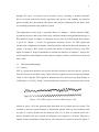
Caton in 1875 and the EEG signals in human brain was discovered by Hans Berger in
1920(Figure 1) [15] [16]. Firstly, a brief introduction to neurons is presented in this section.
Figure 1.First EEG signal recorded by Hans Berger [16]
Neuron or nerve cell is the structural and functional unit of central nervous system. The
essential of nervous system function is information transfer that not only transmits from
one part of a cell to another but also between cells [17]. If there is a stimuli works on a
neuron, dendrites will give respond and transmit nerve impulse to cell body. Then nerve
impulse will be transmitted to other neuron. The structure of a neuron is shown in Figure 2.
12
Each neuron has a cell body which is the metabolism center and the nutrition center of
nerve cell.
Figure 2. The structure of a neuron [18]
In a neuron, three elements make neuron different from other cells. These elements are
axon, dendrite and synapse. The axon is a thin cylinder that transmits electrical signals or
nerve impulse along its body from cell body to its terminal bundle. The length of axon
ranges from micrometer to meters and the diameter of axon is almost unchanged all
through its length [17]. Dendrites are branched from cell body and connected to axons or
the dendrites of other cells. It is thicker and shorter than axon. Different from the function
of axon, dendrites usually receive information from other neuron or somewhere else in the
body. Sometimes, dendrites can also transmit electrical impulse like axon, even work for
both information input and output [17]. Synapses are the junctions of axons and dendrites,
or the junctions of dendrites and dendrites of other cells, which function is transmitting
information from one part of nervous system to other parts. The transmitted information is
called as action potential that is a temporary change of membrane potential [18].
Membrane potential is a potential recorded from the membrane, which usually changes
with the synaptic activities.
After the neuron is introduced briefly, the concept of brain electrical activity can be
defined. It is a summation of postsynaptic potential occurred in a large number of
pyramidal neurons and apical dendrites. EEG signals are not recorded from one specific
neuron, but are formed by the strong currents during synaptic excitations of large number
of neurons in the cerebral cortex through electrodes [19].
13
1.1.2 Brain Rhythms
EEG is a direct way to show the brain activities. It is a good way to describe brain rhythms
with EEG signals in clinical field [19]. Depending on different frequency ranges, EEG
waves can be classified into five major bands that are listed in Table 1 [19]. Gamma
represents the waves of above 30Hz and other bands range from 1-30Hz.
Table 1. EEG wave bands
Band
Frequency (Hz)
Delta (δ)
1-4
Theta (θ)
4-7
Alpha (α)
7-13
Beta (β)
13-30
Gamma (γ)
30+
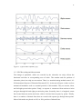
These typical rhythms are shown in Figure 3. They are not only different in frequency
ranges, but also are different in terms of state of human. Alpha wave is the basic rhythm of
a normal adult brain. It occurs when a conscious human is closing eyes and disappears
when human is opening eyes or thinking [20]. Beta wave is associated with active thinking
and accepting information outside. Delta wave appears normally in babies and a human
that sleeps deeply. Theta wave is usually recorded in young children or a human in early
sleep or meditation [21].
14
Figure 3. Typical EEG rhythms [16]
1.1.3 EEG Recording and Measurement
The change of potentials, which are recorded by the electrodes on scalp, reflects the
functional activities in corresponding area of brain. The number and the position of
electrodes placed on scalp are not random. There is a standard setting method named “1020 International System of Electrode Placement”[15]. As shown in Figure 4, there are four
anatomical landmarks work as essential position in this method. They are nasion, inion,
and left/right pre-auricular points. Firstly, an equator is constructed from nasion to inion
and goes through left and right pre-auricular points. Secondly, there is a longitude center
line located between nasion and inion, which is divided into ten parts by points. Thirdly,
there is a number of latitude lines that are coaxial with equator go through these points.
Most of electrodes are placed on 10% or 20% position of latitude lines.
15
Electrodes are named using the rules below. The name of an electrode consists of number
for identifying the hemisphere location and letter for identifying the lobe. The electrodes
located on the left hemisphere are represented by odd number while the electrodes located
on the right side are represented by even number. The number becomes smaller when the
electrode is gradually close to mid line. The English letter is short for the name of the area
that electrodes are placed on. The letters F, T, P, O and Fp refer to frontal lobe, temporal
lobe, parietal lobe, occipital lobe and frontal polar respectively. Letter C means central
position and Z represents the electrode to be found on the center line.
Figure 4. (a) electrode settings for the placement of 21 electrodes, (b) and (c) represents
the placement in three-dimensional [15].
16
1.2
Brain Computer Interface
BCI is a technique that makes an interface between human and other devices by using the
control signals produced from brain electrical activities completely without body
movement or speaking [22]. Furthermore, brain electrical activities are acquired directly
from the neurons by electrical device without peripheral nervous system and muscle [23].
In order to establish a BCI, an appropriate input signal should be selected at first. One
condition is that a signal can reflect different states. The other one is that signal can be
acquired promptly and identified efficiently. Nowadays, several methods and tools are
suitable for observing brain signal in BCI, such as electroencephalography (EEG),
magnetoencephalography (MEG) and functional magnetic resonance imaging (fMRI) [24].
In this thesis, EEG is chosen as input signal due to its easy collection and low cost. EEG
signals will appear and have meaningful changes if human is stimulated by external force
or controlled by consciousness. Furthermore, EEG can reflect various human activities
such as visual stimuli, gaze angle and cognitive states [25] However, EEG signals are easy
affected by the interference outside since they are acquired from scalp.
1.2.1 The Structure of BCI
Generally, a BCI system includes three functional modules: signal acquisition (acquiring,
amplifier, filter, A/D converter), signal processing (feature extraction, feature translator),
external application. The basic principle of a BCI system is presented in figure 5. The
signal acquisition is the input part, which obtains and records brain electrical signals.
Subsequently the signals are digitized and sent to the signal processing. In this module, the
feature of brain signals is extracted and translated into useful device commands through
different algorithms. And then commands are sent to the external devices of different level,
such as computer, wheelchair, robotic arm and prosthetic limb. At last, external devices
give users feedback for adjusting system inputs. The details of different parts are described
in Table 2.
17
Figure 5. The basic principles of any BCI [26]
Table 2. The components and functions of BCI system [26]
Components
Function
controller
Controller gives the orders and then brain electrical activities
appear.
electrode
They are placed on different positions of brain. They detect and
acquire the brain electrical activities in the form of digital signal.
amplifier
Because the EEG signals are weak and easily disturbed by noise,
amplifier and band filter can make them stronger and clearer.
Feature extraction
Analyze the signal and transform into a reduced set of feature,
which is easy to read and process by computer
Feature translator
Based on the feature signals, it outputs commands to
communicate with external machine or human. Feature extraction
and translator are the important parts of BCI system. Keep
improving analysis and translation algorithm is an efficient way
to increase veracity and optimize the BCI system
External application
Convert signal to the action in real, such as cursor movement,
keyboard input and robotic arm moving
Feedback
Feedback shows results in a direct way, and help controller adjust
18
brain signal immediately. For example, design a bar to show the
value of power.
Depending on the electrode position, there are mainly two ways of capturing brain waves:
invasive, non-invasive techniques. In invasive BCI devices, electrodes are implanted
directly into the brain and acquire signals from the grey matter. With this method, the
position of electrode is stable and the highest quality signals are acquired comparing with
other two methods [24]. However, the scar-tissue is formed and body may react to a
foreign matter in brain. They may cause the signals to become weaker and even disappear
at last. This method will attract more attention as the developing of biological materials
and micromachining techniques [25]. In non-invasive BCI, electrodes are positioned on the
scalp of the brain. In despite of producing poorer signals than other techniques, this method
developed widely in human subjects since it is the most user-friendly technique by far.
Nowadays, EEG has received great concerns in the research field of non-invasive
technique [26].
1.2.2 Types
As introduced previously, brain signal such as EEG is a complicated object to study. Some
phenomena of EEG are still studied and their origins are still in exploration. However,
some phenomena have been decoded and controlled by human. Based on these decoded
phenomena, several research approaches including P300 evoked potentials, visual evoked
potentials, slow cortical potentials and sensorimotor rhythms (mu and beta rhythms), are
mainly used in EEG based BCI system to solve communication or control tasks. They will
be discussed below separately.
Event Related Potential (ERP) is a special kind of brain evoked potential. It is produced
when brain is processing information related to certain event. P300 is kind of ERP, which
appears 300ms after some infrequent stimuli. It is proven that the more infrequent the
event, the more significant the P300 potential [25]. A typical application of P300 based
BCI is to find a specific word, number or other symbol from a matrix. The most significant
advantage of P300 based BCI is the short training period for user.
19
Visual evoked potential (VEP) is another kind of brain evoked potential. It responses to the
visual stimuli produced during the processing of visual information. According to the
frequency, VEP can be divided into transient VEP (TVEP) and steady-state VEP (SSVEP).
TVEP occurs when the frequency is below 6 Hz and SSVEP occurs when the stimuli
changes at a higher frequency [27]. The principle of SSVEP based BCI is presented below.
Firstly, several virtual buttons are arranged and the brightness of each button is modulated
at different frequencies for the visual stimulation for experimenter. Secondly, experimenter
visually selects a button. Then the amplitude of SSVEP on this button increases and it can
be identified. The requirement of the SSVEP based BCI is that user should be enabled to
stare at the target.
Slow cortical potential (SCP) are the slow voltage shifts in the cortex that last 1s to 10
seconds [28]. It belongs to the EEG signals below 1Hz and it is related to motion and
cortical activity. It is proven that people can regular SCP by themselves [29]. Patients
learned to shift amplitude of SCP to produce positive deviation or negative deviation by
feedback training. There are many factors affect the performance of this method such as
the patient’s mental and physical condition, motivation, external environment, or the
relationship with people around [29].
When human is awake and relax, 8-12 Hz EEG activity that can be detected in the main
sensorimotor cortex is called Mu rhythm. Mu rhythm is usually related to beta rhythm. The
increase and decrease of these rhythms are affected by real or imagined motor movement
[30]. Increases in these rhythms are called event related synchronization while decreases in
these rhythms are called event related desynchronization.
Among the several research methods above, both P300 and SSVEP are brain evoked
potentials. P300 based BCI extracts time domain feature and SSVEP based BCI extracts
frequency-domain characteristics. Both of these methods have features of little time
training, easy extraction and high accuracy. Both of SCP and sensorimotor rhythm are
easily affected by subjective factors such as mood, fatigue and attention. Furthermore, they
need a long time training to produce brain signal in specific mode.
20
2
PREVIOUS EEG BASED BCI RESEARCH
The development of BCI technology is not smooth. BCI was too strange to be taken
seriously in scientific research. This is because that the reliability and resolution of
detected brain signal is not in a high level. Furthermore, there was no suitable equipment to
record real-time high variable brain signals [31].
However, the situation of BCI research has changed radically during last two decades. BCI
research changed from an unpopular subject to a hot topic that was studied all over the
world. There are several reasons for such change. Firstly, BCI research is a fresh
multidisciplinary subject concerning the cultural areas of neuroscience, physiology,
engineering, computer science and other technical. Hence the development of BCI research
was benefited from the fast development of all these technical especially the computer
science. For example, advanced computer hardware and software can perform complicated
analysis and processing of brain signals accurately and efficiently [22]. Secondly, the
disabled people have attached more and more attention in society, BCI as an auxiliary
technology also gained more support and demand. Last but not least, some original and
user-friendly applications appear in the view of public which can be used in the normal
daily life, such as entertainment. These applications broadened the scope of BCI research.
An overview of various BCI applications will be presented below.
BCI is a suitable assistant technology to help the people with severe motor disabilities and
neurological disorders. According to the level of damage, the potential target populations
of BCI applications are Locked-In State (LIS) patients and the people with partially
paralyzed organs or disabled parts. LIS patients are the people who are almost paralyzed
except the eyes. There are various applications to help these two kinds of people in
different fields, such as communication, motor restoration and locomotion. Furthermore,
BCI are also gradually used to help healthy people for entertainment.
2.1
Communication
Communication is one of the primary demands for patients even the LIS patients. Many
BCI applications are designed for the communication which is based on eyes movement.
This is because that the movement of eyes is a basic function of people even the LIS
21
people. One of most popular applications for communication is speller. The general
principle of speller is that several letters are displayed on screen and then a letter is
selected by user through BCI. Hinterberger, T. et al. reported that a SCP based BCI system
can be used for speller [32]. In their research, the selection of a letter from an alphabet had
to be divided into a number of binary selections because the number of brain response
classes is two. After two letters were chosen, corresponding words were available for
patients to choose.
To use eye blinks is another type of control signal to design a speller. Chambayil, B. et al.
[8] designed a virtual keyboard based on eye blinks. The virtual keyboard included 26
English letters and space to separate words. Its principle was that users selected one target
from three options by producing different times of eye blinks. Firstly, 27 symbols were
divided into three blocks. Each block was a 3x3 matrix with nine letters and then user
selected one block by producing single, two or three blinks. Secondly, the chosen block
was separated into three set of three letters and then user selected again by eye blinks. At
last, user repeated the procedure and selected one letter from three remaining letters. There
is another kind of speller that also used this method of selection. Corley, J. et al. [33]
designed a BCI based virtual keyboard with EMOTIV EPOC headset. The input of this
virtual keyboard was not only based on eye blinks but more variable. It allowed customers
to choose most suitable facial feature for themselves as input signal, such as left or right
wink and smile. In order to design an application towards all users, the input signal also
included custom neural states. At last a short-term training was necessary for customers to
familiarize themselves with producing the corresponding neural states to control the virtual
keyboard.
There are many other methods to design a speller, such as a letter speller based on standard
Graz-BCI designed by Obermaier et al. [9] and a famous P300 based spellers designed by
Farwell and Donchin [34]. P300 based speller is very popular because it does not require a
long time training and it is still continually improved by many researchers [35][36][37][38].
2.2
Motor Restoration
Stroke, spinal cord injury or other nervous system injuries are the main reasons that cause
paralysis and disability. These diseases dramatically limit the patients’ activity space. They
22
have need of long-term therapy and require intensive home care services [39]. With the
help of BCI applications, motor therapies become more effective and reduce the intensity
of patient-practitioner interaction.
EEG based BCI could combine with functional electrical stimulation (FES) technology to
help to restore movement [22]. Tavella et al. demonstrated that this way can be used to
restore whole hand grasping [40]. FES delivered impulses which cause muscle contraction
and BCI was used to turn on/off by opening and closing hand. However, FES requires the
patients have residual movements at least, so it is not suitable for severely injured patients.
Pfurtscheller et al. [41] has already developed a method to control hand orthosis for this
kind of patients. In this study, they demonstrated that a patient can control an implanted
neuroprosthesis based on BCI system after a short training. It proposed a possible approach
for clinical purposes.
Furthermore, stroke damages the primary motor cortex where produces the signals of
traditional BCI devices, hence Fok, S. et al. [4] designed a novel approach for hemiparetic
patients to control hand by means of ipsilateral Cortical Physiology, namely using
unaffected cortex ipsilateral to the affected limb. The theoretical basis of this new method
is that distinct electrophysiological features from motor cortex related to ipsilateral hand
movements [42]. Another highlight of this method was the usage of new device which
saves the cost and training time.
2.3
Locomotion
BCI applications also give lots of help to disable people and old people in the field of
locomotion. Intelligent wheelchair is one of most popular applications in this field.
Borgolte stated that more than 2,000,000 people could get benefit from individually
configurable intelligent wheelchair [43]. Generally intelligent wheelchair has two basic
functions. One function is automatic navigation, such as avoiding obstacles and selfpositioning. The other function is human-machine interaction, such as BCI.
To design an efficient wheelchair, there are several requirements for BCI system. Firstly,
the number of the types after classifying brain signals should reach to the number of
wheelchair motions such as going forward, turning left, turning right and stop. Secondly,
23
due to the target customer is human, the BCI should be non-invasive and has a training
period as short as possible. Thirdly, the information transfer rate and accuracy should keep
in a high level. EEG based BCI is the main study object in field of wheelchair due to it is
non-invasive. In 2005, Tanaka et al. presented a study on EEG based control of an electric
wheelchair. It was remarkable that controlling the wheelchair direction was achieved only
by EEG signals [3]. After this, some more advanced researches have been presented over
the past few years. Rebsaman et al. presented a P300 based brain controlled wheelchair
that could work in a specific place, such as hospital environment [44]. In this research, they
purposed a motion guidance strategy to ensure a high level information transfer rate. The
detail was stated as follow. There was a path of wheelchair movement made by user at first.
After that, guidance path was stored by system and there are several user-defined points on
the path, so user only needs to decide where to stop with BCI control. An improved
research was done by the same groups in 2007 [45]. Other BCI paradigms such as SSVEP
and alpha rhythm are also applied to intelligent wheelchair [46][47].
2.4
Entertainment
In recent years, entertainment has become a popular BCI application for non-disabled
people. It allows a novel communication channel which is more challenging than common
channels such as keyboard, mouse and joystick. Millan (2003) designed a BCI for a
classical Pacman game [48]. In this research, Millan made two mental missons to represent
two motions of Pacman. The same group made a research about controlling the motion of a
Khepera robot to avoid obstacle and turn smoothly [49]. Furthermore, Roman made a
Berlin BCI for several classical games [11]. As the development of EMOTIV, there are
many new video games, such as Spirit Mountain Demo Game and Cortex Arcade, which
specifically match these novel headsets. It provides a new developing direction of game
industry.
24
3
INDUSTRIAL ROBOTS
3.1
Brief Introduction to Robot
Robots often appear in the science fiction, movies and cartoon. The term robot first
appeared in a drama that written by Karel Capek [50]. Karel Capek coined a robot slave
named “Robota” which has human’s appearance, characters and functions. In this drama,
Robota is described as a machine that worked for human like a salve.
In real world, robot is an electronic mechanical device which combines human-like
specialty and the features of machine. Usually it has an anthropomorphic shape and a rapid
response to the sensory inputs. It also can communicate with other machines and has the
abilities of analyzing and making decisions. Furthermore, it has the advantages of machine.
It can be substituted for humans in hazardous or uncomfortable work environments. It also
can work long hours with high accuracy and repeatability that cannot be attained from
human.
Unlike other technological term has a clear concept, the definition of robot is changed as
the science and technology goes on. This is because that robotics is still developing. New
models are continuously designed and new functions keep upgrading. In 1984,
International Standardization Organization made a definition for robot according to the
Robot Institute of America [51]. Robot is a reprogrammable and multifunctional
manipulator, devised for the transport of materials, parts, tools or specialized systems,
with varied and programmed movements, with the aim of carrying out varied tasks.
Therefore, robotics is an advanced subject concerning the cultural areas of computer,
controlling, mechanics, information technology, sensor technology and electronics.
3.2
Definition of Industrial Robots
Industrial robot is a kind of robot and has reached the level of a mature technology. As
defined by ISO 8373, industrial robot is an automatically controlled, reprogrammable,
multipurpose manipulator programmable in three or more axes, which may be either fixed
in place or mobile for use in industrial automation applications [52]. The key element of
25
this definition is reprogrammable. When the current task is finished, an industrial robot can
be reprogrammed and equipped with the necessary tools to work on another different task.
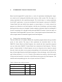
Industrial robots have already been widely used in many industries for different purposes.
According to the international federation of robotics (IFR) report, robot sales increased to
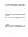
178,132 units in 2013, which is the highest level recorded for one year [53]. The
worldwide annual supply of industrial robots by industries is shown in Figure 6. The most
important customer of industrial robots was the automotive industry. The share of the total
supply was about 39%. The automotive industry has continuously increased the number of
robot installations since 2011 from 60,000 units to 69,400 units in 2013. Furthermore, the
typical applications of industrial robots included handling, welding, assembly, dispensing,
processing and others.
Figure 6. The worldwide annual supply of industrial robots by industries [53]
3.3
Classification
There are many way to classify industrial robots. According to mechanical structures,
industrial robots can be classified as serial robot and parallel robot. Serial robot includes
articulated robot, cylindrical robot, linear robot and selective compliance assembly robot
arm (SCARA) robot. They will be introduced separately below.
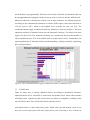
Articulated robot is a robot with rotary joints, which works just like human’s arm. It can
have one or two rotary joints, and more joints can be used if necessary. As it is shown in
26
Figure 7, rotary joints are arranged in a chain and one joint supports another further in the
chain, so articulated robots allow a large range of motion and high flexibility. Hence
articulated robots commonly are used on manufacturing line.
Figure 7. 6-axis articulated robot
Cylindrical robot is a robot arm that moves around a cylinder shaped pole (Figure 8). It has
two linear axes and one rotary axis. Normally it has a tight structure and it can be
combined with tool such as pneumatic clamps. For this reason, cylindrical robot is able to
perform handling and assembly. Nowadays, the cylindrical robot is not popular due to the
articulated robot that has more versatility and more degrees of freedom.
Figure 8. The cylindrical robot
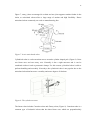
The linear robot includes Cartesian robot and Gantry robot (Figure 9). Cartesian robot is a
common type of industrial robots that has three linear axes which are perpendicularly
27
oriented at each other. Because all three axes are linear rather than rotational, this type of
robots has a simple structure that can be used in bad environment for a long time and easy
to maintain. Its most common application is computer numerical control machine.
Following the written commands, the robot can move very fast and precisely and thus are
suitable for different processing functions such as milling and drawing. Comparing to
Cartesian robot, a gantry robot usually encloses its work envelope from outside. As it
shown in Figure 9, this big robot stands on four strong beams. It can lift objects with heavy
weight and large dimensions. As a result, gantry robots can be used for handling and
assembly.
Figure 9. (a) Cartesian robot (b) Gantry robot
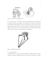
A SCARA robot is one of the most popular types of robots on an assembly line (Figure 10).
It is designed by imitating human’s shoulder, elbow and wrist. As it shown in figure,
SCARA robot has two rotary joints in parallel which make robot move in horizontal, and a
linear joint makes robot move in vertical. It is famous for high speed, efficiency and low
cost. It also has large range of motion, and it is faster and more precise than Cartesian
robot. However, it cannot carry heavy weight, so it works best when handling small objects
such as small electronic items.
28
Figure 10. SCARA Robot and its workspace
As it is shown in Figure 11, it is IRB 360 FlexPicker, a parallel robot made by ABB Group.
In a parallel robot, the work platform or the end-effector is connected to the basis by
several kinematic chains forming a closed loop. Parallel robots are stiffer, faster, and more
accurate than serial robots. However, they have a limited workspace due to the legs may
collide. They have been used in several applications such as flight simulator, parallel
machine tool. They also have a good performance on assembly line.
Figure 11. ABB IRB 360 FlexPicker
3.4
Robot Components
An industrial robot, as a system, consists of machinery, end-effector, actuation, sensors,
controller, and processor. Machinery consists of two sections: One is body-and –arm which
29
is used for positioning the objects in the robot’s workspace. The other is wrist assembly
which has two or three degree of freedom (DOF) such as roll, yaw and patch. End-effector
is attached to wrist assembly. It directly connects to the objects, tools or other machines to
finish the required tasks. Generally end-effectors are not made by robot manufacturers but
specifically designed by customers for a purpose. Actuation is the device which provides
the power for robot. Common types of actuation are servomotors, pneumatic or hydraulic
cylinders and electric motors. Sensors are used to collect information of internal state of
robot and outside environment. They enhance the motility and adaptability of robot.
Sometimes sensors are more effective than human’s sense organ. The sensor feedback
information can support controller to control and adjust the motion of actuation. The
controller receives the data from the computer and controls the motion of actuation to
move the arm according to the purposes. The processor is the central part of robot system.
It calculates the motions of joins and processes other data of robot system. It generally
requires an operation system, programs and peripheral equipment such as information
panel and alarm.
3.5
Robot Kinematics
Kinematics studies the relationship between robot joints variables, position and orientation
as a function of time without consideration of the force and moment that cause motion [54].
It consists of forward kinematics and inverse kinematics. The relationship between forward
kinematics and inverse kinematics is illustrated in Figure 12. Forward kinematics studies
the position and orientation of end-effector when joints variables and links parameters are
known. Inverse kinematics studies the joints variables when links parameters are known
and the position and orientation of end-effector are given. It is a much more complex
problem than forward kinematics. It will be mentioned later.
Figure 12. Relationship between forward kinematics and inverse kinematics[54]
30
3.5.1 Forward Kinematics
The main body of robot consists of joints and links. Joints provide relative motion, and
their types are linear and rotary. The rigid members between joints are links. Each couple
of joint and link provides a DOF. The links are serial and each link connects with other two
links at most.
Formulating a suitable kinematics model is very important for analyzing the manipulator of
robot. One of common coordinate systems used in kinematics modeling is Cartesian
coordinate system. There is a Cartesian coordinate system in every joint. In coordinate
system, i is the joint number and Ai is the axis of joint. Generally the first link A0 is
attached on the base and there is a reference coordinate system. The transformation
between two coordinate systems consists of a rotation and a translation. Each rotation or
translation can be expressed by a matrix and then the transformation can be represented by
the cross product of matrices known as homogenous matrix.
Denavit and Hartenberg (1955) mentioned that using homogenous matrix was a useful way
to represent the rotation and the translation [55]. Homogenous matrix is a 4x4 orthonormal
matrix which requires four link parameters: ai, αi, di, and θi, which refer to the link length,
link twist, link offset and joint angle separately. These parameters are known as DenavitHartenberg (DH) method parameters, which have become the typical factors for describing
robot kinematics. In order to determine DH parameters, a Cartesian coordinate frame is
attached to the D-H method. Zi axis of the coordinates is pointing along the rotary or
sliding direction of the joints. There is a coordinate frame of a general manipulator in
figure 13, where origin oi is located on the point of intersection of ai and Ai, zi axis
coincides with Ai. ai is the length between zi-1 and zi pointing along xi-1 axis. αi is the angle
that zi-1 rotates to z around xi-1 . di is the distance between xi-1 and xi along with z i. θi is the
angle that xi-1 rotates to xi around zi. ai should equal or greater than 0, while αi, di, and θi
could be positive or negative.
31
Figure 13. A Cartesian coordinate system attached to the DH method
The general transformation matrix
-
for the process that coordinate system i-1 is
transferred into coordinate system i can be obtained as follows. Firstly, system i-1
translates along zi axis by a distance di. Secondly, it rotates around the zi axis by an angle θi.
Thirdly, it translates along the xi-1 axis by a distance
. Al last it rotate around the xi-1 axis
by an angle αi. DH in mathematical order from right to left:
i
i
(
)
(
) (
)
][
=[
(
)
][
][
]
=[
The solution of forward kinematics:
i
i
i
( )
where qi=(
i
( )
i-
i(
),
) is the joint variable
]
32
3.5.2 Inverse Kinematics
Inverse kinematics solves the problem of where to place the joints to get the end-effector in
the right place. In a problem of inverse kinematics, numerical and closed- form methods
exist. A system, which has rotary and linear joints, should have numerical solution when
its DOF is less than six. However, this method takes a long time to calculate. In reality,
there are a few special conditions. For instance, a number of axes of joints intersect;
several axes are parallel or vertical. In such conditions, a 6 DOF robot has an analytical
solution. Therefore, industrial robot are tried to design simply in order to satisfy the special
conditions. In this thesis, analytical or closed-form methods are concentrated.
Generally, the inverse kinematics problem has multiple solutions. Moreover, singularities
and nonlinearities make the problem more difficult to solve. There are a number of
methods to eliminate unnecessary solutions. 1) Choosing a suitable solution according to
the limits of workspace and joint angle. 2) Choosing a suitable solution by avoiding the
possible obstructions in workspace. 3) Choosing a suitable solution which has smallest
movement amount of all joints.
In 1981, Paul mentions a method to computes the inverse kinematics problem. Firstly, we
suppose that the transformation matrix of end-effector relating to the base frame
i
can be
written as
i
[
]
where n, s, a is the unit vector and matrix [n s a] represents the rotational elements of
transformation matrix. px, py and pz denotes the elements of the position vector.
Secondly, to solve the inverse kinematics of the first joint, the first translation matrix
is
pre-multiplied on both ends of the forward kinematics equation. After that, making the
corresponding elements of both sides equal and unknown q1 can be shown through an
expression with known elements n, s, a, px, py pz and fixed link parameters.
(
)
i
i-
33
Thirdly, pre-multiplying next matrix and another unknown q2 can be shown through a new
expression.
(
)
(
i)
(
)
(
i-
i
)
(
)
i
Repeat the above processes till all the expression are obtained.
The suitable solution should be selected by human. Usually arctg2(y,x) function are used
to select suitable θ. It can place arctg(y/x) in the right sub-frame
(
)
{
}
34
4
THE EMOTIV SYSTEM
To acquire and process the EEG data from human brain, many non-invasive electrical
devices came into the view of public. Neurosky Mindwave is a neuroheadset that can
response to user brainwaves and monitors user attention levels. It has provided a set of
software tools for third party developers to develop applications [56]. However, lack of
channels is the main limitation of this device. In this research, multiple-electrode headsets
are considered, such as the Advanced Neuro Technology (ANT) acquisition system and
EMOTIV EPOC system. ANT has a standard medical headcap which has 128 electrodes
covering all the major brain cortical area and offers several software tools. EMOTIV
system applies a commercial data acquisition device which has 16 electrodes and a set of
software. For the research edition, the total cost is 699$ [56]. Finally the EMOTIV EPOC
is chosen in this research for a number of reasons: 1). It is a low cost system which is much
cheaper than ANT. 2). Matthieu Duvinage etc. have researched the performance of the
EPOC for P300-based applications [57]. The results show that EPOC is able to record EEG
data and could be used for communication systems. Lievesley, R. etc. have done a research
of the performance of EPOC. They found that EPOC could build a channel between brain
and computer [58]. 3). EPOC has a powerful software development kit for consumers.
Many research teams have acquired signals with this system [59].
4.1
EMOTIV EPOC
The EMOTIV EPOC is revolutionary new personal BCI interface which is made by a
bioinformatics company in San Francisco, USA. It gives human a possibility to control the
world with mind. EMOTIV EPOC consists of a headset kit for acquiring EEG signals and
a software sort for processing and analyzing the data [60].
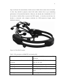
The appearance of headset is shown in Figure 14. It looks like a normal headphone and
several arms branch from the position of each ear. In the end of each arm there is a slot for
inserting sensor. For instance, two rubber sensors are inserted in the slots behind each ear
lobe to correct the position of headset. More details of the headset are listed in table 3. 16
sensor units are placed in corresponding slots according to “10-20 International System of
Electrode Placement”. Among of them, two sensors located in P3 and P4 form a feedback
35
loop as reference for measurement of other sensors. Before these sensor units are inserted
in slots, they should be properly wetted with saline solution first to get outstanding
performance of electrode/skin interface. Moreover, the headset has a bandwidth of 0.2-45
Hz and has a build-in filter to process the EEG signals. At last but not the least, the
headset is connected with computer wirelessly by USB transceiver dongle, which
facilitates customer.
Figure 14.Tthe EPOC headset
Table 3. The parameters of EMOTIV neroheadset [60]
Number of channels
14 (plus CMS/DRL references, P3/P4
locations)
Channel
names
(International
10-20 AF3, F7, F3, FC5, T7, P7, O1, O2, P8, T8,
locations)
FC6, F4, F8, AF4
Sampling method
Sequential sampling. Single ADC
Sampling rate
128 SPS (2048 Hz internal)
Bandwidth
0.2 - 45Hz, digital notch flters at 50Hz and
60Hz
Filtering
Built in digital 5th order Sinc flter
36
Dynamic range (input referred)
8400μV (pp)
Connectivity
Proprietary wireless, 2.4GHz band
Power
LiPoly
Battery life (typical)
12 hours
Impedance Measurement
Real-time contact quality using patented
system
4.2
Software Development Kit (SDK)
After the hardware of EPOC is introduced, the software development kit will be presented
below. Two Glossaries are introduced firstly. One is Emostate which is data structure
holding information about the current status of all activated EMOTIV detections. The other
is EmoEngine which decodes and processes the data acquired by headset. EmoEngine
provides a few built-in brainwave processing suites including Expressiv, Affectiv and
Cogntiv. It also monitors the headset battery level, contact quality and the raw EEG data
[62].
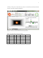
4.2.1 EMOTIV Control Panel
The EPOC Control Panel is a convenient operation panel for customer to connect with the
EPOC headset. All these mentioned functionality can be used through the EPOC Control
Panel supplied by EMOTIV Company. After it is opened, the EmoEngine will start
automatically. The Control Panel preprocesses and classifies the acquired brain signals.
Moreover, it gives feedback of battery and contact quality to the user. It also helps the user
to explore the EMOTIV detection suites. The main panes of Control Panel are introduced
below.
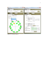
As shown in Figure 15, the EmoEngine Status Pane provides the current state of
EmoEngine, such as system up time, wireless signal quality and battery power. On the
right side of the pane, it is the sensor locations. Each circle refers to one sensor and its
approximate position on user’s head. Different sensor colors indicate different contact
qualities. The colors and corresponding qualities are listed in Table 4. Ideally, all the
sensors should be green which represents the best contact quality. It is acceptable that most
sensors are green and some are yellow. The user name and the number of headset are also
shown on this pane. The default number is zero.
37
Figure 15. The EmoEngine Status Pane
Table 4. The senor color and corresponding quality
The Color of sensors
Contact quality
Black
No signal
Red
Very poor signal
Orange
Poor signal
Yellow
Fair signal
Green
Good signal
Under the EmoEngine Pane, the Control Panel has a tab for each processing suites
mentioned above. The Expressiv suite is designed to measure the facial expressions by
reading EMG signals. In Figure 16, a robot face is on the left side. When user wears the
headset, the facial expressions that are performed by user are displayed on the face of the
robot. There is a series of graphs in the middle of the panel, which indicate the feature of
various signals that are related to expressions. The expressions which are displayed include
normal eyes blink, right/left wink, eye movements to the left and right, raise brow, furrow
brow, smile, clench, right/left smirk and laugh. The sensitivity adjustments for these
expressions are offered on the right side of the Expressiv suite.
38
Figure 16. The Expressiv suite panel
The Affectiv suite is developed to measure and display the user’s emotional responses. It is
usually used in video games. Currently it can display many affective types shown in Figure
17. Levels of these emotion detections are translated into graphical measurement on the
panel.
Figure 17. The Affectiv suite Panel
39
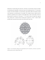
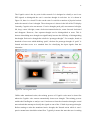
The Cognitiv suite is the key suite in this research. It is designed to classify a user’s raw
EEG signals to distinguish the user’s conscious thought in real time. As it is shown in
Figure 18, there is a virtual 3D cube on the suite. It could do a number of physical actions
under the control of user’s thought. The action power is shown in the left of the 3D display.
Currently, Cognitiv suite can measure 13 active thought: push, pull, movement to left/right,
lift, drop, rotate left/right, rotate clockwise/counterclockwise, rotate forward/ backward
and disappear. However, four separate thought can be distinguished at most. This is
because that adding more thought can significantly increase the difficulty of distinguishing
the thought. Each active thought has a built-in “prototype thought”. For example, based on
hundreds of test cases which thinking “push”, the data for prototype thought of “push” is
formed and then serves as a standard base for classifying the input signals from the
electrodes.
Figure 18. The Cognitiv suite
Unlike other mentioned suites, the training process of Cognitiv suite must be done first
otherwise Cognitiv suite cannot automatically detect user thought. The training process
enables the EmoEngine to analyze user’s brainwaves from the electrodes through a neural
network and then attempt to classify the signals as one of the 13 built-in prototype thought.
Before starting to train the mentioned active thought, the Neutral action which is user’s
passive mental state should be trained first. Typically it means the state that user is reading
40
or relaxing. It works as a reference for other active thought. Providing more Neural action
training is a good way to get better Cognitiv performance. During the training process, user
should think deliberately.
There are mainly two main potential problems for user during training period. One is to
find what the prototype thought is. The more thought matches up to the prototype thought
defined by EMOTIV the higher the skill rating is. The other is to think consistently for the
full training period.
The Cognitiv suite moreover supplies a function that user can customize and control
imported 3D objects. Firstly a user-defined model is imported and placed in desired
position. Secondly custom scenery is created and then this 3D object can be used through
Cognitiv suite. It is possible to make a simple simulation of robotic arm in future research.
4.2.2 EmoComposer
EmoComposer is designed to stimulate the behavior of EmoEngine and headset and then
send user-defined orders to Control Panel and other applications. It is a convenient tool for
EMOTIV SDK developers. It help user understand the working principle of different suites
early in the development process. It also offers user help in the way of testing the program
in the development cycle. Interactive mode is one useful mode of EmoComposer. It allows
user to define and send mock signals to other EMOTIV application. The operation
interface is shown in Figure 19. On the top of the panel, the player number and wireless
quality can be chosen. The length of EmoState interval can be defined and the interval can
be sent repeatedly. In contact quality tab, overall contact quality can be chosen. If it is
chosen as “custom”, the contact quality for each sensor can be chosen separately. Only two
reference sensors always report a CQ value of good. In detection tab, EmoState detection
values and training results values can be defined. All previously mentioned suite could be
defined in this mode. Firstly the active thought of Cognitiv suite can be chosen and its
power can be defined. Secondly the user emotion could be chosen. At last the facial
expressions could be defined. In a ward, the EmoComposer is an emulator to facilitate the
development of EMOTIV related software.
41
Figure 19. The EmoComposer
42
5
EXPERIMENT SETUP
5.1
The Scope and Setup
In previous chapters, BCI system has been presented and a novel electronic device has
been introduced in detail. In this chapter, the objective of this research, which designs an
EEG based BCI as a bridge of human thought and industrial robot, will be implemented
with previous information. As previously mentioned, in the Cognitiv Suite of EMOTIV
Control Panel, there is a virtual 3D cube that can be used for training to control several
actions (pull, push, right, left, lift and drop) by means of user thought. In this research,
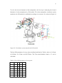
these actions are used to represent the translation of the end-effector of an industrial robot.
As it is shown in Figure 20, we assume that motion pull represents the +X axis and push
motion represents the -X axis. Likewise, right represents the +Y axis and left represents the
-Y axis. Lift represents the +Z axis and drop represents the -Z axis. Furthermore, the action
power which can be measured through an acquisition program written by user is used to
represent the incremental motion of end-effector in each direction. It is concluded that we
use cubic motion for training our thought and then we used action power for controlling
the robot. After that, the inverse kinematic of an industrial robot is used to determine the
angles of joints through the position of end-effector. An operation panel is designed to
display the desired values for user.
Z
Y
X
Figure 20 coordinate system of cube
43
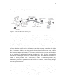
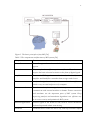
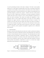
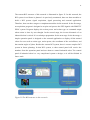
The current BCI structure of this research is illustrated in figure 21. In this research, the
BCI system in red frame is planned. As previously mentioned, there are three modules to
build a BCI system: signal acquisition, signal processing and external application.
Therefore, there are three stages to complement modules in this research. In the first stage,
an acquisition program is designed to acquire and process the EEG signals with EMOTIV
EPOC system. Program displays the action power and action type as command output
when action is done by user thought. In the second stage, the inverse kinematic of an
industrial robot is solved. It is a technique preparation for the next stage. In the last stage, a
simple operation panel is designed as the external application to display all the wanted
values for user such as action type, action power, the coordinate of the end-effector, and
the rotation angles of joints. Besides the current BCI system, there is a more complex BCI
system in future planning. In that BCI system, a robot control panel will receive the
numbers from the operation panel and uses them to control industrial robot. The control
panel of industrial robot is a very complicated system to design, so it will be finished in
future work.
Figure 21.The BCI structure in this research
44
5.2
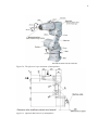
Equipment
There are two major components that were considered in this research: 1) EMOTIV EPOC
Neuroheadset, a device for the EEG data acquisition 2) industrial robot. The EMOTIV
EPOC Neuroheadset in this research is premium version which includes the raw EEG data
and software Testbench. The industrial robot is the Mitsubishi RV-3SB Robot Manipulator.
The detail of this robot will be described in later section. There is a laptop as the third
component which is used to process the signal and edit the control program. For the future
signal processing platform, more processors may be used.
5.3
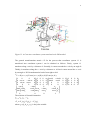
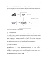
EMOTIV Application Program Interface
Application Program Interface (API) plays an important role of computer programming. It
is in close relationship with EmoEngine and Emostate previously mentioned. The
correlation between different components of process in this research is shown in Figure 22.
The EmoEngine receives the control command from user edited program through
EMOTIV API and then connect to EPOC Neuroheadset. Then EmoEngine processes the
EEG signal acquired from headset and translates detection results into EmoState which
reflects user’s facial and cognitive state. The handling of EmoState data also depends on
fitting EMOTIV API functions.
Figure 22. The components and theirs relationship
45
The utilization of EMOTIV API is illustrated in Figure 23. It helps user to understand the
functions of EMOTIV API which includes connecting to EmoEngine, detecting and
handling new EmoStates, and querying for new EmoState.
Figure 23. The utilization of EMOTIV API
5.4
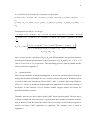
Acquiring Program
The program for this research was written in Microsoft Visual C++. This is because that
C++ is easy to call the American National Standards Institute (ANSI) C libraries exposed
in the EMOTIV API. The code implementing the acquiring program is separated into three
stages: connecting to the EMOTIV headset via EMOTIV API, real-time reading and
decoding EMOTIV events and showing corresponding results on the screen, and closing
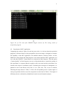
the connections when user is done. The complete code is listed in Appendix 1.
5.4.1 EMOTIV connection
Generally, there are two methods to build the connection with headset: using the
EE_EngineConnect
or
using
EE_EngineRemoteConnect.
In
this
research,
EE_EngineRemoteConnect was selected because program application is desired to connect
to EMOTIV Control Panel which queries connection status and provides Cognitiv Suite to
control the virtual cube. Thus the function for connecting headset is:
EE_EngineRemoteConnect (“127.0.0.1”, 3008)
46
5.4.2 Real-time decoding and handling EmoStates
There are three basic steps to read and decode the information acquired form the EPOC
headset: creating EmoEngine and EmoState Handle, querying the most recent EmoEngine
event and identifying the event type, and decoding the EmoState if it is new. EmoEngnine
Handle is a structure that store a handle that is generated by EE_EmoEngineEventCreate()
and EmoState Handle is allocated by EE_EmoStateCreate():
EmoEngineEventHandle eEvent
= EE_EmoEngineEventCreate ( );
EmoStateHandle eState
= EE_EmoStateCreate ( );
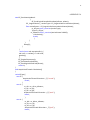
Before the last two steps, there is a problem to solve firstly. This problem is how to
achieve the real-time acquisition. Therefore, the problem of real-time acquisition can be
solved by calling:
While (true);
{
Sleep (5);
};
By using While (true), the program will give a response immediately if there is a
EmoEngine event. To detect every event, most applications should poll at least 10-15 times
per second or one time per 0.05s. sleep (5) can give system a break in order to avoid the
problem of system crash, where 5 represents the break time is 0.005s which is much short
than 0.05s.
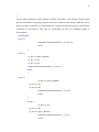
The second step is retrieving the EmoEngine event by calling EE_EngineGetNextEvent()
and identifying it. There are three main types of EmoEngine events: Hardware-related
events, new EmoState events and Suite-specific events. Hard ware-related events are the
events that connect or disconnect headset with computer, which include EE_UserAdded
and EE_UserRemoted. New EmoState events are the events that are related to user’s facial
and cognitive state. The most common event of this type is EE_EmoStateUpdated. Suitespecific events are the events for training and configuring Cogntiv or Expressiv Suites,
such as EE_CognitivEvent. In order to identify the type of EmoEngine event,
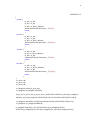
EE_EmoEngineEventGetType () can be used:
int state = EE_EngineGetNextEvent(eEvent);
47
if (state == EDK_OK) {
EE_Event_t eventType = EE_EmoEngineEventGetType(eEvent);
}
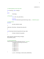
The last step is to decode the EmoState event. In this research, the Cognitiv Suites is the
main unit to concentrate, so only Cognitiv action is detected and decoded. Action type
represents the direction and action power represents the value of motion. They can be
obtained by follow codes:
EE_CognitivAction_t actionType = ES_CognitivGetCurrentAction(eState);
float actionPower = ES_CognitivGetCurrentActionPower(eState);
type=static_cast<int>(actionType);
power=static_cast<int>(actionPower*100.0f);
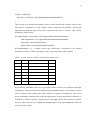
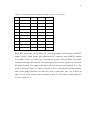
EE_CognitivAction_t is a Cognitiv action type enumerator. Comparing to the defined
enumerator values in Table 5, the integer value of the actionType can be gained.
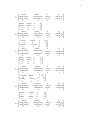
Table 5. Action motions and their defined enumerator values
Action
Value
Action
Value
Neutral 0x0001 Rotate Left
0x0080
Push
0x0002 Rotate Right
0x0100
Pull
0x0004 Rotate Clockwise
0x0200
Lift
0x0008 Rotate Counterclockwise 0x0400
Drop
0x0010 Rotate Forward
0x0800
Left
0x0020 Rotate Backward
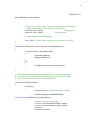
0x1000
Right
0x0040
As previously mentioned, there are six possible actions in this case: pull/push, left/right,
and lift/drop. The action should be trained before experiment starts, so only these six types
can be detected after training and other actions are ignored automatically. The action
power of thought is initially used as the moving distance of robot end-effector. However, it
is difficult to obtain a specific required power of thought. Hence the direction of robotic
action is what we focus on, no matter the thought-power. At last, presenting the results on
screen by follow codes:
48
std::cout<<"actiontype:" <<static_cast<int>(actionType) << "," <<
"actionpower:"<<static_cast<int>(actionPower*100.0f)<<std::endl;
5.4.3 EMOTIV disconnection
In the last stage, disconnection is finished and the internal memory is released by calling:
EE_EngineDisconnect ();
EE_EmoStateFree (eState);
EE_EmoEngineEventFree (eEvent);
5.5
Inverse Kinematic of RV-3SB Robot Manipulator
The industrial robot used in this research is Mitsubishi RV-3SB Robot Manipulator with
high speed and high precision. It is a 6-axis type with brakes for all axes. The first three
joints are used to determine the position of end-effector, while the rest three joints are used
to decide the orientation of end-effector. In this research, we only consider the translation
of the end-effector in this thesis work, so the angles of first three joints are demanded and
displayed. The physical representation of this robot arm is shown in Figure 24. It consists
of several parts: Base, Waist, Shoulder, Upper arm, Elbow, Elbow block, Fore arm, Wrist
and mechanical interface. The optional dimensions are illustrated in Figure 25.
49
Figure 24. The physical representation of manipulator
Figure 25. Optional dimensions of manipulator
50
To solve the inverse kinematic of this manipulator, the first step is analyzing the forward
kinematic of robot manipulator by DH method. The robot manipulator coordinate system
attached to the DH method is established according to its structure. It is shown in Figure 26.
Figure 26. Coordinate system attached to D-H method
The four DH parameters of every joint are defined and listed in Table 6, where a1= 95mm,
a2=245mm, a3=135mm and d4=270mm. The Then transformation matrix
calculated.
Table 6. Four DH parameters of every joint
Joint i di
θi
ai
αi
1
0
θ1 0
0o
2
0
θ2 95
-90o
3
0
θ3 245 0o
4
270 θ4 135 -90o
5
0
θ5 0
90o
6
0
θ6 0
-90o
-
can be
51
]
=[
=[
]
]
=[
]
=[
]
=[
=[
]
]
=[
=[
]
]
=[
=[
=[
]
]
52
]
=[
After transformation matrix of each joint is calculated, the general transformation matrix
equation is:
0
6=
0
1
1
2
2
3
3
4
4
5
5
(1)
6
In this research, we assume that the general transformation matrix is:
]
=[
Where rkj represent the rotational elements (k and j=1, 2 and 3). p x, py and pz denote the
elements of position vector. The equations of position elements are listed below:
px= cos [a4cos(
+
) - d4 sin(
+
py= sin
+
) - d4 sin(
+
[a4cos(
pz= -a4 sin(
+
) - d4 cos(
+
) + a3cos
) + a3cos
) - a3sin(
+a2]
+a2]
)
After forward kinematics is solved, the inverse kinematic can be solved with previous
mentioned method. To find the inverse kinematics solution for the first joint as a function
of the known elements of
(
, the link transformation inverses are pre-multiplied as follow:
)
][
=[
]=
[
]
=
=[
(
)
(
(
)
(
)
)
(
)
]=A1
53
The A1(2,4) in each side of equation should be equal:
(2)
⁄ )
(
A1(1,4) and A1(3,4) in each side of equation should be equal separately:
(
(
)
(
)
(
)
(
)
(3)
)
(4)
Squared equation (2), (3) and (4), and then add them together:
(5)
We define that
(6)
Where
)⁄(
(
We assume that
√
, where
) (7)
(
⁄
)
substitute into equation (6):
(
)
⁄
(
⁄√
(
(
⁄
√
)
)
)
⁄√
(
In order to calculate , (
(
)
0
[
=[
)
)
(
)
)
6 =(
(
( )
)
0
1
is pre-multiplied to the both side of equation (1).
1
(
(
2
2
3
3
)
)
4
4
5
5
6
(
(
)
)
(
(
)
)
]
]=A2
54
A2 (1,4) and A2(2,4) in both side of equation are equal, then
(
)
(
(
)
)
(
(
)
)
(
(
)
)
(
(7)
)
(8)
From equation (8) and (9), we can get:
(
)
(
)
(
)
(
)
(
)
(
)
(
)
(
)
=
[
(
(
)
(
)(
)(
Now, we have got the expression of
)
(
)
]
)
with DH parameters and position elements.
According to standard specifications of robot, the ranges of
are: -170 to +170,
-180 to 45 and -110 to +81, respectively. The calculating process is done by Matlab and the
codes are shown in Appendix 2.
5.6
Operation Panel
After inverse kinematic of industrial manipulator is solved, an operation panel is built up to
display the real-time information for users. In this research, the panel in Windows system
is based on Microsoft Foundation Classes (MFC). MFC is a library that wraps Windows
API in C++ classes. It includes a default application framework to reduce the workload of
developers. It also includes a lot of windows handle wrapper classes and classes for
predefined windows controls.
Generally, there are two basic steps to build a MFC based operation panel. The first step is
to design a simple and clear user panel. A typical panel has a number of common controls,
such as Button, Check Box and Edit Control. The second step is to edit code in response to
controls and then a MFC application is completed. The complete code is listed in
Appendix 3.
55
5.6.1 Designing User Panel
Firstly building a MFC project follows the MFC Application Wizard. There are two basic
application types: document and dialog. The type of the application in this research is
dialog based which applies a simple interface, and project style is standard MFC. After a
dialog box named “Acquisition” is created, various controls should be added on it. The
common controls in this research are: Button, Static Text and Edit Control. The layouts of
these controls are illustrated in Figure 27. There are nine Edit boxes corresponding to nine
captions to show different text. The meanings of the captions are: Type refers to the type of
the action done by human thought, power represents the action power or the incremental
displacement of the end-effector done by human thought, coordinates is the position of
end-effector in artificial coordinate system, and joint 1-6 mean the angle of each joint
separately. The first three joints are calculated through inverse kinematic with known
position of cube.
Figure 27. The MFC application for presenting
56
5.6.2 Editing Code for Controls
Now it is time to edit code for the controls. Firstly, each edit box is added with a variable.
They are listed in Table 7. There are two main problems to solve in this step: 1) real-time
detecting the signal 2) constantly refreshing edit boxes in real time to display the latest data.
Table 7. The control units and variables
Control name Caption
Variable name
IDC_EDIT1
Type
m_edit1
IDC_EDIT2
Power
m_edit2
IDC_EDIT3
Coordinates m_edit3
IDC_EDIT4
Joint 1
m_edit4
IDC_EDIT5
Joint 2
m_edit5
IDC_EDIT6
Joint 3
m_edit6
IDC_EDIT7
Joint 4
m_edit7
IDC_EDIT8
Joint 5
m_edit8
IDC_EDIT9
Joint 6
m_edit9
1) Real-time detecting the signal
In the codes of acquisition program, while (true) was used to solve the problem of
acquiring in real-time. However, if this function is used directly for button “ok”, the
system will be crashing. If “true” is replaced by a specific number, for example “while
(number<2)”, the program will detect and decode event twice and close then. The problem
is that function “while(true)” intensively uses computer resources all the time, which
makes button”ok” cannot be responded, viz., that system will be halted. In this research,
this problem is solved by using multithread programming. It is an easy and safe way to
perform background calculation and maintenance. Firstly, creating a new class named
“AcquisitionThread” that is based on class CWinThread through MFC class Wizard. A
thread is easily created and operated by function AfxBeginThread ( ). Here is a brief
introduction for it. The definition of this function in Microsoft Developer Network library
is [63]:
CWinThread* AfxBeginThread (
AFX_THREADPROC pfnThreadProc,
57
LPVOID pParam,
int nPriority = THREAD_PRIORITY_NORMAL,
UINT nStackSize = 0,
DWORD dwCreateFlags = 0,
LPSECURITY_ATTRIBUTES lpSecurityAttrs = NULL
);
Where pfnThreadProc points a controlling function for worker thread and it must be
declared as follow:
unsigned int MyThreadFunction (LPVOID pParam);
Parameter pParam is to be passed to the controlling function; it can be a structure because
of LPVOID;
nPriority means the desired priority of the thread. Normally it is 0 and it shares same
priority with main thread;
nStackSize specifies the size bytes of the stack for new thread;
dwCreateFlags specifies an additional flag that controls the creation of the thread. It is 0
and then it runs automatically;
lpSecurityAttrs is structure that specifies the security attributes for the thread. If NULL, it
shares same security attributes with main thread;
Return value is a Pointer to the newly created thread object, or NULL if a failure occurs.
Firstly, pfnThreadProc and other parameters are declared in “AcquisitionThread.h” below,
and it is edited in “AcquisitionThread.cpp” which will be listed particularly in Appendix 3.
static CWinThread * m_pAcquisitionThread;
static unsigned int ThreadAcquisitionDataFunc(LPVOID pParam);
static double * m_pParam4Data;
Secondly, AfxBeginThread ( ) is created in CAcquisitionApp::InitInstance ( ) below and it
will run automatically if this MFC application starts.
If (AcquisitionThread::m_pAcquisitionThread == NULL)
{
AcquisitionThread::m_pAcquisitionThread = AfxBeginThread
(AcquisitionThread::ThreadAcquisitionDataFunc,
(LPVOID)AcquisitionThread::m_pParam4Data);
58
};
At last, other parameters can be defined as default. Therefore, a new thread is built and the
previous mentioned acquiring program should be written in this thread. After the action
power and type are gained, we attach them to a Cartesian coordinate system to describe the
coordinate of end-effector. The code for positioning the cube in coordinate system is
shown below:
switch(Type){
case 0 :{
AcquisitionThread::Direction =_T("neural");
break;
}
case 2 :{
m_dX = m_dX-m_dPower;
m_dY = m_dY;
m_dZ = m_dZ;
AcquisitionThread::Direction =_T("push");
break;
}
case 4 :{
m_dX = m_dX+m_dPower;
m_dY = m_dY;
m_dZ = m_dZ;
AcquisitionThread::Direction =_T("pull");
break;
}
case 8 :{
m_dX = m_dX;
m_dY = m_dY;
m_dZ = m_dZ+m_dPower;
AcquisitionThread::Direction =_T("lift");
break;
59
}
case 16 :{
m_dX = m_dX;
m_dY = m_dY;
m_dZ = m_dZ-m_dPower;
AcquisitionThread::Direction =_T("drop");
break;
}
case 32 :{
m_dX = m_dX;
m_dY = m_dY-m_dPower;
m_dZ = m_dZ;
AcquisitionThread::Direction =_T("left");
break;
}
case 64 :{
m_dX = m_dX;
m_dY = m_dY+m_dPower;
m_dZ = m_dZ;
AcquisitionThread::Direction =_T("right");
break;
}
}
m_dx=m_dX;
m_dy=m_dY;
m_dz=m_dZ;
Where m_dx, m_dy, m_dz refer to the position of the end-effector in X axis, Y axis, Z axis
separately. m_dPower refers to the action power.
60
2) Constantly refreshing edit boxes in real-time to display the latest data
Function OnTimer ( ) is a suitable way to refresh the edit boxes in real time. It can be called
by class CWnd and its derived class. Firstly, creating a timer in the program of button ”ok”
as follow:
void CAcquisitionDlg::OnBnClickedOk()
{
SetTimer(nIDEvent, nElapse, NULL);
}
Where nIDEvent is the ID of timer and nElapse represents interval time.
At last, edit the timer in function CAcquisitionDlg::OnTimer(UINT_PTR nIDEvent). This
function includes the codes for the assigning the necessary variables to different controls.
Button ”OK” is used to start the program and “Cancel” is used to quit.
61
6
EXPERIMENT FOR SYSTEM TESTING
Based on the designed BCI system above, a series of experiments including three stages
are carried out for testing the feasibility and accuracy of this system. The first stage is a
testing experiment for the acquisition program. The second stage is a testing experiment
for the MFC application. As previous mentioned, EmoComposer connected to EMOTIV
Control Panel and sent built-in data signals as system input to it. In this research, the
program was allowed to use EmoComposer with the aim of making a quick and testable
prototype before using user’s thought. Another method to obtain the input for building BCI
system is acquiring user’s thought actually through EMOTIV headset. In the last stage, an
experiment of the designed BCI system is done. Actual signals acquired from headset were
used as inputs instead of stimulated signals from EmoComposer.
6.1
Testing of the Acquisition Program
The aim of this test is to examine whether the acquisition program detects the type and the
power of cube motion. The steps of this experiment are described below. At first,
EMOTIV Control Panel and EmoComposer were started and then Acquisition program
was run. After that, EMOTIV Control Panel was connected to EmoComposer. Then the
option “Contact Quality” in EmoComposer was set as all good and we started to control
the cube. In this test, there are six groups corresponding to six cube motions: push, pull, lift,
drop, left and right. Based on the defined enumerator values, the integer value of the action
type of these motions is 2, 4, 8, 16, 32 and 64. The motions are sorted by value from small
to large and each motion is sent twice with different action power by EmoComposer. The
motions and corresponding given value of power are listed in Table 8.
Table 8. Motion type and given power
Motion type (integer value) Power 1 Power 2
Push (2)
10
20
Pull (4)
30
40
Lift (8)
50
40
Drop (16)
60
50
62
Left (32)
60
50
Right (64)
80
60
The result of this testing is stated as follow. When acquisition program was run, it is shown
that “EMOTIV Engine started! Type ‘exit’ to quit, ‘help’ to list available commands… New
user 0 has used.” When we sent the first command following the plan through
EmoComposer, the action type and power were shown on the screen instantly as shown in
Figure 28 (a). After all the planned motions were done, the final result is shown in Figure
28 (b).
63
Figure 28. (a) The state after EMOTIV Engine started, (b) The testing results of
acquisition program
6.2
Experiment of MFC Application
Comparing the results in Figure 28 and the given value, it is obvious that the acquisition
program is efficient. Based on this precondition, the second stage is designed to examine
the feasibility of the MFC application. The detailed scheme is stated as follow. At first,
EMOTIV Control Panel and EmoComposer were started and then MFC application was
run. After that, EMOTIV Control Panel was connected to EmoComposer. Then the option
“Contact Quality” in EmoComposer was set as all good and then we started the testing. In
this experiment, we assumed that the cognitive state was neural and the end-effector was
located at the origin of coordinate system. Considering the workspace of manipulator, we
planned to move end-effector from (300, 0, 0) to (400, 400, 150) to test six motions
following the steps shown in Table 9. At last, the corresponding series of joints angles of
each given position which are used for comparison are also listed in Table 9. The angles of
different joints are calculated by Matlab based on the inverse kinematic analysis.
64
Table 9. The planned steps and optional angles of joints in each step
Step Coordinate
Joint 1
Joint 2
Joint 3
1
300,0,0
0
-83.7561 74.1052
2
350,0,0
0
-74.2459 62.1745
3
350,350,0
45.0000 -48.8836 23.1428
4
410,350,0
40.4860 -40.2399 8.4255
5
410,410,0
45.0000 -30.8478 -7.9948
6
410,410,100 45.0000 -39.7626 -12.8455
7
410,410,170 45.0000 -41.6590 -23.1331
8
400,410,170 45.7073 -44.1032 -19.2352
9
400,400,170 45.0000 -46.4155 -15.6018
10
400,400,150 45.0000 -46.0697 -12.3395
When MFC application was run, there was a pop-up messagebox with message “EMOTIV
Engine started” which means that application has connected with EMOTIV Engine
successfully. Firstly, we need to place end-effector at point (300,0,0). When we sent the
commands through EmoComposer, the action type, power and the angles were shown on
the dialog instantly. The angles at the point (300,0,0) moreover are displayed on it. The
result is shown in Figure 29. Then we started to move following the planned position.
After all the planned motions were done, the result of point (400, 400, 150) is shown in
Figure 30 and all the wanted values are listed in table 10. The results of other points are
shown in Appendix 4.
65
Figure 29. The wanted information at point (300,0,0)
Figure 30. The wanted information at point (400,400,150)
66
Table 10. The results of the MFC test
step
Coordinate
Joint 1
Joint 2
Joint 3
1
300,0,0
0.000000
-83.756127
74.105179
2
350,0,0
0.000000
-74.245943
62.174465
3
350,350,0
45.000000 -48.883555
23.142761
4
410,350,0
40.486012 -40.239886
8.425479
5
410,410,0
45.000000 -30.847764
-7.994793
6
410,410,100 45.000000 -39.762559 -12.845492
7
410,410,170 45.000000 -41.658955 -23.133148
8
400,410,170 45.707319 -44.103210 -19.235226
9
400,400,170 45.000000 -46.415548 -15.601815
10
400,400,150 45.000000 -46.069683 -12.339454
6.3
The Experiment of BCI System with Human Thought Input
Before the last experiment, a training period is arranged for us to be familiar with the
EMOTIV EPOC system. The virtual cube in the Cognitiv Suite previously mentioned was
used to train user thought. First of all, the “neutral” state was trained for three times to
make the cube stay in a static situation. Then action “push” was trained. This action was
trained four times and the skill rating was 12%. After that action “pull” was added and
trained four times. The skill rating was 9%. We trained two motions for much more times
in two hour. The skill rating was 23% and 19% separately and then we made ten attempts
and eight attempts were successful. Then we began the last experiment.
In the last experiment, we run the designed BCI system and utilize human thought as input
instead of mock signals through EmoComposer. Because both action “push” and “pull” are
trained, we plan to achieve action “pull” five times and each time lasts 3sec. After one
action is detected, we will keep mind neutral for 5sec since we need time to record the
result. First of all, headset was put on the head of the experimenter and the connect quality
of all electrodes or most of them at least should be regulated to good. The current state of
control panel was shown in Figure 31. There were three electrodes with fair performance
while others were good. Then we run EMOTIV Control Panel and the MFC based dialog.
After that we started to do action “pull” by experimenter thought. The coordinates, action
power and angles were displayed on dialog. The information of the passed points is listed
67
in Table 11. The power of each action was 0 since we recorded the result when mind state
is neural. The results are listed in Appendix 5.
Figure 31. The state of Control Panel in the last experiment
Table 11.The information of the passed point
step Coordinate type
Joint 1
Joint 2
Joint 3
1
179,0,0
Pull
0.000000 -125.743626 103.512084
2
443,0,0
Pull
0.000000 -58.141668
38.285042
3
520,0,0
Pull
0.000000 -44.109804
15.070857
4
255,0,0
push
0.000000 -94.022779
84.645699
5
328,0,0
pull
0.000000 -78.281153
67.472444
68
7
DISCUSSION
According to the results from the first and second testing, it is proven that both the
acquisition program and the MFC project meet the requirements that are detecting and
processing the input signals accurately and instantly. They can be used in the future
research of BCI studying due to its satisfactory performance.
According to the result of the last experiment, it is shown that the human thought, which
are in the form of EEG signals, can be read and decoded truly and are used to achieve the
action through designed BCI system after training our thought by controlling the virtual
cube. These actions could represent the motion of industrial robot. Therefore designed BCI
system provides a bridge between the motions of robot and the human thought.
However, there are unexpected results obtained in the last experiment. As shown in Table
11, the incremental displacement in every step was different and even the direction was
wrong sometimes. In other words, the action power of human thought is hard to control
with high level accuracy and even the action type detected by EMOTIV headset is
incorrect sometimes. Besides the shortages of EEG signals and EMOTIV product
previously mentioned, there are several possible reasons for unexpected results: 1).The
contact quality of few electrodes is not good. That the electrodes were lack of saline may
be the reason for bad contact quality. Another possible reason was that EMOTIV headset
was not worn perfectly. 2).The training time was not long enough to achieve the desired
result. This is the main reason for unexpected results. The intensity of thought is hard to
control accurately by human himself although it can be expressed by EEG signals and
measured by EMOTIV software. Therefore a longer training time is needed. Moreover,
identifying two actions at the same time the made the test more difficult than detecting one
action.
In response to the defects above, there are a number of ways to improve. 1). Handling the
electrodes carefully and replacing old electrodes regularly due to the oxidation of the
electrodes [64]. 2). Wearing the headset and placing every electrodes strictly in right
69
position following the instruction of EPOC User Manual. 3). Taking a longer training time
and summing up experiences of training in order to increase the skill rating.
70
8
CONCLUSION AND FUTURE WORK
BCI system, as a new communication channel between brain and machine, has developed
rapidly during the past few years. It is not only applied to improve the life quality of those
disabled people but also it enters the field of controlling robot even industrial robot with
the appearance of several new devices. Controlling industrial robot by using BCI is an
innovative research task which has great expectation. With the help of BCI system, it is
possible that industrial robot is controlled by human thought directly and this method is
different from the traditional methods, such as manual control and numerical control. In
this research, we built an EEG based BCI system for implementation of controlling an
industrial manipulator by means of human thought.
In this thesis, we firstly introduced BCI and selected EEG signals as the input signals of
BCI system due to its easy collection. Furthermore, we made a short review of previous
research on EEG based BCI. We made a briefly introduction to industrial robot and studied
robot kinematics. Meanwhile we chose EMOTIV EPOC as the research instrument due to
its acceptable performance and low cost, and made a detailed introduction. With EMOTIV
applications, we designed the BCI system in three steps: 1). we designed a C++ program
that cooperated with EMOTIV EPOC for acquiring and processing the detected EEG
signals. 2). we solved the inverse kinematics of MITSUBISHI RV-3SB industrial robot. 3).
we designed a MFC based dialog as operation panel and solved the problem of real-time
acquisition by using multithread programming and timer. In the last part of this research,
we tested acquisition program and MFC application separately. In the tests, both of them
had satisfactory performance. Finally, we designed an experiment to examine the designed
BCI system with human thought. We found that the human thought was successfully
detected and processed by the BCI system we built. Furthermore, we offered a few
suggestions to improve the accuracy of designed BCI system.
In this research, we chose EMOTIV EPOC as research equipment due to its low cost and
user-friendly. EMOTIV Neuroheadset was used to acquire EEG signals from user’s brain.
Furthermore, other EMOTIV applications such as EMOTIV Control Panel and
EmoComposer were used to process the signals and were applied to build BCI system.
71
These EMOTIV applications are designed on the basis of built-in prototype which is based
on lots of data. However, the algorithm and data sample still have room for improvement.
In the future study, we can obtain the raw EEG signals by EMOTIV TestBench and
process raw signals by different filters. Based on lots of experimental data, we may also
improve the algorithm.
In this research, we trained our thought by controlling the motion of a virtual cube to
represent the movement of end-effector of industrial robot. In the future, we can build a 3D
model of industrial robot and insert it into the Cogntiv Suite of EMOTIV Control Panel.
Furthermore, as shown in Figure 20, we can also build a panel to control RV-3SB robot
and make it as the external device of BCI system. In the end, this research is an attempt of
BCI system used in the field of robot controlling and builds the foundation of future work.
72
REFERENCE
[1]. Vidal, Jacques. 1973. Towards Direct Brain–computer Communication. Annual Review of
Biophysics and Bioengineering, vol. 2, pp. 157–180.
[2]. Robert Bogue. 2010. Brain-computer interfaces: control by thought. Industrial Robot: An
International Journal, vol. 37, pp. 126-132
[3]. Tanaka, K., Matsunaga, K., Wang, H.O. 2005. Electroencephalogram-based control of
an electric wheelchair. IEEE Trans. Robot., vol. 21, pp. 762–766.
[4]. Fok S. & Schwartz, R. 2011. An EEG-based Brain Computer Interface for
Rehabilitation and Restoration of Hand Control following Stroke Using Ipsilateral
Cortical Physiology, 33rd annual International Conference of the IEEE EMBS, August
30 – September 3, Boston, USA
[5]. Treder, M.S. & Blankertz, B. (C) overt attention and visual speller design in an ERPbased brain-computer interface. Behavioral and Brain Functions. 2010, 6, 28.
[6]. Liu, Y., Zhou, Z., Hu, D. 2011. Gaze independent brain-computer speller with covert
visual search tasks. Clinical. Neurophysioogy., vol. 122, pp. 1127–1136.
[7]. Birbaumer, N. et al., 1999. A spelling device for the paralysed. Nature, vol. 398, pp.
297–298.
[8]. Chambayil, B., Singla, R., Jha, R. 2010.Virtual Keyboard BCI Using Eye Blinks in
EEG.. 6th IEEE International Conference on Wireless and Mobile Computing,
Networking and Communications (WiMob’
), Niagara Falls, Canada, October, pp.
466–470.
[9]. Obermaier, B., Muller, G.R., Pfurtscheller, G. 2003. “Virtual keyboard” controlled by
spontaneous EEG activity. IEEE Trans. Neural Systems and Rehabilitation
Engineering. Vol. 11, pp. 422–426.
[10]. Lin, C.T. et al., 2010. EEG-based Brain-computer Interface for Smart Living
Environmental Auto-adjustment. Journal of Medical and Biological Engineering.
Vol. 30, pp. 237-245
[11]. Roman, K., Benjamin, B., Gabriel, C., Klaus-Robert, M. 2007. The Berlin Brain Computer Interface (BBCI)-Towards a new communication channel for online
control in gaming applications. Multimedia Tools and Application. Vol. 33, pp. 73–
90
73
[12]. Middendorf, M., McMillan, G., Calhoun, G., Jones, K.S. 2000.Brain-computer
interfaces based on the steady-state visual-evoked response. IEEE Trans. Rehabil.
Eng. vol. 8, pp. 211–214.
[13]. Lalor, E.C., Kelly, S.P., Finucane, C. 2005. Steady-state VEP-based brain-computer
interface control in an immersive 3D gaming environment. EURASIP Journal on
Advances in Signal Processing. pp. 3156–3164.
[14]. Finke, A., Lenhardt, A., Ritter, H. 2009. The MindGame: A P300-based braincomputer interface game. Neural Networks. Vol. 22, pp. 1329–1333.
[15]. Swartz, B.E., Goldensohn, ES. 1998. Timeline of the history of EEG and associated
fields. Electroencephalography and Clinical Neurophysiology. Vol. 106, pp.173–
176.
[16]. Patel, N. D. 2011. An eeg-based dual-channel imaginary motion classification for
brain computer interface. Master thesis, in Lamar University
[17]. Levitan, I.B. & Kaczmarek, L.K. 2002. The neuron: cell and molecular biology. 3 rd
ed. New York: Oxford University Press
[18]. Sanei, S. & Chambers, J.A. 2007. EEG Signal processing. Chichester, John Wiley &
Sons Ltd
[19]. Nunez, P.L. & Srinivasan R. 2006. Electric fields of the brain: the neurophysics of
EEG. 2 nd ed. New York: Oxford University Press
[20]. Niedermeyer, E. & Fernando L. 2005. Electroencephalography: Basic Principles,
Clinical Applications, and Related Fields, 5th ed. Philadelphia: Lippincott Williams
& Wilkins
[21]. Cahn, B. & Polich, J. 2006. Meditation states and traits: EEG, ERP, and
neuroimaging studies. Psychological Bulletin Vol. 132, pp. 180–211.
[22]. Nicolas-Alonso, L.F. & Gomez-Gil, J. 2012. Brain computer interfaces, a review.
Sensors. Vol. 12, pp. 1211-1279
[23]. Wolpaw, J. R. et Al., 2000. Brain–computer interface technology: a review of the
first international meeting, IEEE Transactions on Rehabilitation. Engineering, vol.
8(2), pp. 164–173.
[24]. Tonet, O. et al., 2008. Defining brain–machine interface applications by matching
interface performance with device requirements, Journal of Neuroscience Methods,
Vol. 167, pp. 91-104
74
[25]. Lebedev, M. A., & Nicolelis, M. A. L. 2006. Brain–machine interfaces: past, present
and future. Trends in Neurosciences, Vol. 29, pp. 537-546.
[26]. Wolpaw, J.R. et al., 2002. Brain-computer interfaces for communication and control.
Clinical Neurophysiology, Vol. 113, pp. 767-791
[27]. Gao, X. R., Xu, D. F., Cheng, M., Gao, S. 2003. A BCI-based environmental
controller for the motion-disabled. IEEE transactions on neural systems and
rehabilitation engineering, Vol. 11(2), pp. 137-140.
[28]. Birbaumer, N., Elbert, T., Canavan, A.G., Rockstroh, B. 1990. Slow potentials of the
cerebral cortex and behavior. Physiological Reviews, Vol. 70, pp. 1–41.
[29]. Hinterberger, T., Schmidt, S., Neumann, N., Mellinger, J., Blankertz, B., Curio, G.,
Birbaumer, N. 2004. Brain-computer communication and slow cortical potentials.
IEEE Transactions on Biomedical Engineering, Vol. 51, pp. 1011–1018.
[30]. Pfurtscheller, G. and Neuper, C. 2001. Motor imagery and direct brain-computer
communication, Proceedings of the IEEE, vol. 89, pp. 1123-1134, 2001.
[31]. Wolpaw, J.R. 2007. Brain–computer interfaces as new brain output pathways. The
journal of physiology, Vol. 579, pp. 613-619
[32]. Hinterberger, T.et al., 2004. Brain-computer communication and slow cortical
potentials. IEEE Trans. Biomed. Eng, Vol. 51, pp. 1011–1018
[33]. Corley, J. et al., 2012. Brain-computer interface virtual keyboard for accessibility
[online
document].[Accessed
20
March
2015].
Available
at
http://gray.cs.ua.edu/pubs/iasted-hci-2012.pdf
[34]. Farwell, L.A. & Donchin, E. 1988. Talking off the top of your head: Toward a mental
prosthesis utilizing event-related brain potentials. Electroencephalogr. Clin.
Neurophysiol. Vol. 70, pp. 510–523.
[35]. Sellers, E. W. & Donchin, E. 2006. A P300-based brain-computer interface: initial
tests by ALS patients. Clin. Neurophysiol., Vol. 117, pp. 538-548.
[36]. Fazel-Rezai, R & Abhari, K. 2009. A region-based P300 speller for brain-computer
interface. Can. J. Elect. Comput. E, Vol. 34, pp. 81–85.
[37]. Townsend, G. et al., 2010. A novel P300-based brain-computer interface stimulus
presentation paradigm: Moving beyond rows and columns. Clin. Neurophysiol.
Vol.121, pp. 1109–1120.
[38]. Ahi, S.T., Kambara, H., Koike, Y. 2011. A dictionary-driven P300 speller with a
modified interface. IEEE Trans. Neural Syst. Rehabil, Eng. Vol. 19, pp. 6–14.
75
[39]. Wolpaw, J. R. & McFarland, D. J. 2004. Control of a two-dimensional movement
signal by a noninvasive brain-computer interface in humans. Proc. Natl. Acad. Sci,
Vol. 101, No. 51, pp. 17849-17854
[40]. Tavella, M., Leeb, R., Rupp, R., Millan, J.R., 2011. Natural non-invasive hand
neuroprosthesis. International Journal of Bioelectromagnetism, Vol. 13, pp. 92-93
[41]. Müller-Putz, G.R., Scherer, R., Pfurtscheller, G., Rupp, R., 2005. EEG-based
neuroprosthesis control: A step towards clinical practice. Neurosci. Lett. Vol. 382, pp.
169–174
[42]. Wisneski, K.J. et al., 2008. Unique cortical physiology associated with ipsilateral
hand movements and neuroprosthetic implications. Stroke, vol. 39, pp. 3351-3359
[43]. Borgolte, U. et al., 1998. Architectural concepts of a semi-autonomous wheelchair.
Journal of Intelligent and Robotic Systems, Vol. 22, pp.233~253
[44]. Rebsamen, B., Burdet, E., Guan, C., Zhang, H. 2006. A Brain-Controlled Wheelchair
Based on P300 and Path Guidance. Proc. IEEE/RAS-EMBS Int. Conf. on biomedical robotics and biomechatronics (Biorob), pp. 1101-1106
[45]. Rebsamen, B., L.T., Zeng, Q., Ang, V.M.H. 2007. Controlling a Wheelchair Indoors
Using Thought. Intelligent Systems, IEEE, Vol. 22, pp. 18-24
[46]. Mandel, C., Luth, T., Laue, T., Rofer, T. 2009. Navigating a smart wheelchair with a
brain-computer interface interpreting steady-state visual evoked potentials. The 2009
IEEE/RSJ international conference on intelligent robots and systems. pp. 1118-1125
[47]. Ferreira, A. et al., 2007. Human-machine interface based on muscular and brain
signals applied to a robotic wheelchair. Journal of Physics, Vol. 90
[48]. Millán, J.d.R. 2003. Adaptive brain interfaces for communication and control. Proc.
of the 10th International Conference on Human-Computer Interaction, June 22-27,
Crete, Greece
[49]. Millán, J.d.R., Renkens, F., Mouriño, J. & Gerstner, W. 2004. Brain-actuated
interaction. Artificial Intelligence, Vol. 159, 241–259.
[50]. Appuu Kuttan K.K. 2007. Robobtics. New Delhi: I.K. International publishing house
[51]. Schiebe, M., Pferrer, S. 1992. Real-time systems engineering and applications:
engineering and applications. Norwell: Kluwer Academic Publishers.
[52]. Bekey, G.A., Ambrose, R. 2008. Robotics: State of the Art and Future Challenges.
London: Imperial College Press
76
[53]. Executive summary industrial robots. 2014. [online document].[Accessed 20 March
2015]. Available at http://www.ifr.org/industrial-robots/statistics/
[54]. Cubero, S. 2007. Industrial robotics: theory, modeling and control. Mammendorf:
Pro-Literatur-Verlag
[55]. Denavit, J. & Hartenberg, R. S. 1955. A kinematic notation for lower-pair
mechanisms based on matrices. Journal of Applied Mechanics, Vol. 1, pp. 215-221
[56]. EMOTIV eStore. [online document].[Accessed 20 March 2015]. Available at
https://EMOTIV.com/store/app/
[57]. Duvinage, M., Castermans, T., Petieau, M., Hoellinger, T., Cheron, G., Dutoit, T.
2013. Performance of the EMOTIV EPOC headset for P300-based applications.
Biomedical Engineering Online, Vol. 12, pp.1
[58]. Lievesley, R., Wonzencroft, M.& Ewins, D. The Emotiv EPOC neuroheadset: an
inexpensive method of controlling assistive technologies using facial expressions
and thought, Journal of Assistive Technologies , Vol. 5, pp. 67-82
[59]. Gil, J., Gonzalez, I., Alonso, L.F., Garcia, S.A. 2011. Steering a tractor by means of
an EMG-based human-machine interface, Sensors, Vol. 77, pp. 7110-7126
[60]. EMOTIV [Emotiv webpage]. Updated February 1, 2012. [Accessed 20 March 2015].
Available at https://EMOTIV.com
[61]. EPOC User Manual.
[62]. EMOTIV Software Development Kit
[63]. MSDN library. [online document].[Accessed 20 March 2015]. Available at
https://msdn.microsoft.com/en-us/library/s3w9x78e.aspx
[64]. Lang, M. Investigating the EMOTIV EPOC for cognitive control in limited training
time. 2012. Honors Report. Department of Computer Science, University of
Canterbury
77
APPENDICES
APPENDIX 1.1
The complete C++ based code of acquiring program
#include<iostream>
#include<conio.h>
#include<sstream>
#include<cassert>
#include"EmoStateDLL.h"
#include"edk.h"
#include"edkErrorCode.h"
#pragma comment(lib, "Ws2_32.lib")
#pragma comment(lib, "edk.lib")
void Cognitiv(EmoStateHandle eState);
int type;
int power;
int main()
{
EmoEngineEventHandle eEvent
EmoStateHandle eState
unsigned int userID
= EE_EmoEngineEventCreate();
= EE_EmoStateCreate();
= 0;
try{
if (EE_EngineRemoteConnect("127.0.0.1", 3008) != EDK_OK) {
std::cout<<"EMOTIV Engine start up failed."<<std::endl;
}
else {
std::cout << "EMOTIV Engine started!" << std::endl;
}
std::cout << "Type \"exit\" to quit, \"help\" to list available commands..." <<
std::endl;
while (true){
int state = EE_EngineGetNextEvent(eEvent);
if (state == EDK_OK) {
EE_Event_t eventType = EE_EmoEngineEventGetType(eEvent);
EE_EmoEngineEventGetUserId(eEvent, &userID);
switch (eventType) {
// New headset connected, create a new socket to send the animation
case EE_UserAdded:
{
std::cout << "New user "<<userID<< " has added." << std::endl;
break;
78
APPENDIX 1.2
}
case EE_UserRemoved:
{
std::cout << std::endl << "User" << userID << " has been removed." <<
std::endl;
break;
}
case EE_EmoStateUpdated:
{
EE_EmoEngineEventGetEmoState(eEvent, eState);
Cognitiv(eState);
break;
}
}
}
}
}
catch (const std::exception& e) {
std::cerr << e.what() << std::endl;
std::cout << "Press any keys to exit..." << std::endl;
getchar();
}
EE_EngineDisconnect();
EE_EmoStateFree(eState);
EE_EmoEngineEventFree(eEvent);
return 0;
}
void Cognitiv(EmoStateHandle eState)
{
EE_CognitivAction_t actionType = ES_CognitivGetCurrentAction(eState);
float actionPower = ES_CognitivGetCurrentActionPower(eState);
type=static_cast<int>(actionType);
power=static_cast<int>(actionPower*100.0f);
std::cout<<"actiontype:" <<type << ","
<< "actionpower:"<<power<<std::endl;
}
79
APPENDIX 2
The complete Matlab based code for solving inverse kinematics
syms c1 c2 c3 c4 c5 c6 r1 r2 r3 r4 r5 r6 a2 a3 a4 d4
syms r7 r8 r9 px py pz
pi=3.141592654;
a2=95;
a3=245;
a4=135;
d4=270;
% M1...M6 refers to the transformation matrix of each joint
M1=[cos(c1) -sin(c1) 0 0;sin(c1) cos(c1) 0 0;0 0 1 0; 0 0 0 1];
M2=[cos(c2) -sin(c2) 0 a2; 0 0 1 0;-sin(c2) -cos(c2) 0 0;0 0 0 1];
M3=[cos(c3) -sin(c3) 0 a3; sin(c3) cos(c3) 0 0 ; 0 0 1 0;0 0 0 1];
M4=[cos(c4) -sin(c4) 0 a4; 0 0 1 d4; -sin(c4) -cos(c4) 0 0;0 0 0 1];
M5=[cos(c5) -sin(c5) 0 0; 0 0 -1 0; sin(c5) cos(c5) 0 0;0 0 0 1];
M6=[cos(c6) -sin(c6) 0 0;0 0 1 0; -sin(c6) -cos(c6) 0 0; 0 0 0 1];
% the general transformation matrix
T=[r1 r2 r3 px; r4 r5 r6 py;r7 r8 r9 pz;0 0 0 1];
% solve C1, the angle of joint 1
c1=atan2(py,px);
angle1=c1*180/pi;
% solve c3,the angle of joint 3, due to A(1,4) and A(3,4) on both side of equation should
be
% equal then we have:
K=(px^2+py^2+pz^2+a2^2-2*a2*px*cos(c1)-2*a2*py*sin(c1)-a4^2-d4^2-a3^2)/(2*a3);
J=sqrt(d4^2+a4^2-K^2);
c3=atan2(a4,d4)-atan2(K,J);
angle3=c3*180/pi;
% solve c2, the angle of joint 2, A2(1,4)and A2(2,4) on both side of equation should
be %equal then
simplify(inv(M1*M2*M3)*T);
A2=simplify(M4*M5*M6);
% we have:
K1=-pz*(a4+a3*cos(c3))-(d4-a3*sin(c3))*(px*cos(c1)+py*sin(c1)-a2);
K2=(a4+a3*cos(c3))*(px*cos(c1)+py*sin(c1)-a2)-pz*(d4-a3*sin(c3));
c23=atan2(K1,K2);
c2=c23-c3;
angle2=c2*180/pi;
str=[px,py,pz];
disp(str);
disp(angle1);
disp(angle2);
disp(angle3);
80
APPENDIX 3.1
The complete C++based code for MFC application
1). “AcquisitionThread.h”
#pragma once
// AcquisitionThread
class AcquisitionThread : public CWinThread
{
DECLARE_DYNCREATE(AcquisitionThread)
protected:
AcquisitionThread(); // protected constructor used by dynamic creation
virtual ~AcquisitionThread();
public:
virtual BOOL InitInstance();
virtual int ExitInstance();
protected:
DECLARE_MESSAGE_MAP()
public:
static CWinThread * m_pAcquisitionThread;
public:
static unsigned int ThreadAcquisitionDataFunc(LPVOID pParam);
static int m_dType;
static int m_dPower;
static int m_dX;
static int m_dY;
static int m_dZ;
static double m_dx;
static double m_dy;
static double m_dz;
static double m_dangle1;
static double m_dangle2;
static double m_dangle3;
static double m_dAngle1;
static double m_dAngle2;
static double m_dAngle3;
static void Calculation();
static CString Coordinates;
static CString Direction;
static CString Angle1;
static CString Angle2;
static CString Angle3;
static double k;
public:
static double * m_pParam4Data;
};
81
APPENDIX 3.2
2). “AcquisitonTheard.cpp”
// AcquisitionThread.cpp : implementation file
#include "stdafx.h"
#include "Acquisition.h"
#include "AcquisitionThread.h"
#include<iostream>
#include<conio.h>
#include<sstream>
#include<cassert>
#include <cmath>
#define PI 3.141592654
#include"EmoStateDLL.h"
#include"edk.h"
#include"edkErrorCode.h"
#pragma comment(lib, "Ws2_32.lib")
#pragma comment(lib, "edk.lib")
CWinThread * AcquisitionThread::m_pAcquisitionThread = NULL;
double * AcquisitionThread::m_pParam4Data = NULL;
int AcquisitionThread::m_dType = 0;
int AcquisitionThread::m_dPower = 0;
int AcquisitionThread::m_dX = 0;
int AcquisitionThread::m_dY = 0;
int AcquisitionThread::m_dZ = 0;
double AcquisitionThread::m_dx = 0;
double AcquisitionThread::m_dy = 0;
double AcquisitionThread::m_dz = 0;
double AcquisitionThread::m_dangle1 = 0;
double AcquisitionThread::m_dangle2 = 0;
double AcquisitionThread::m_dangle3 = 0;
double AcquisitionThread::m_dAngle1 = 0;
double AcquisitionThread::m_dAngle2 = 0;
double AcquisitionThread::m_dAngle3 = 0;
double AcquisitionThread::k = 0;
int Type = 0;
CString AcquisitionThread::Coordinates =_T(" ");
CString AcquisitionThread::Angle1 =_T(" ");
CString AcquisitionThread::Angle2 =_T(" ");
CString AcquisitionThread::Angle3 =_T(" ");
CString AcquisitionThread::Direction =_T("neural");
// AcquisitionThread
IMPLEMENT_DYNCREATE(AcquisitionThread, CWinThread)
82
APPENDIX 3.3
AcquisitionThread::AcquisitionThread()
{
}
AcquisitionThread::~AcquisitionThread()
{
}
BOOL AcquisitionThread::InitInstance()
{
// TODO: perform and per-thread initialization here
return TRUE;
}
int AcquisitionThread::ExitInstance()
{
// TODO: perform any per-thread cleanup here
return CWinThread::ExitInstance();
}
BEGIN_MESSAGE_MAP(AcquisitionThread, CWinThread)
END_MESSAGE_MAP()
// AcquisitionThread message handlers
unsigned int AcquisitionThread::ThreadAcquisitionDataFunc(LPVOID pParam)
{
// my own code for the thread
EmoEngineEventHandle eEvent
= EE_EmoEngineEventCreate();
EmoStateHandle eState
= EE_EmoStateCreate();
unsigned int userID
= 0;
try{
while(true){
int state = EE_EngineGetNextEvent(eEvent);
if (state == EDK_OK) {
EE_Event_t eventType = EE_EmoEngineEventGetType(eEvent);
EE_EmoEngineEventGetUserId(eEvent, &userID);
switch (eventType) {
case EE_UserRemoved:
{
CString str2=_T("User has been removed!");
AfxMessageBox(str2);
break;
}
83
APPENDIX 3.4
case EE_EmoStateUpdated:
{
EE_EmoEngineEventGetEmoState(eEvent, eState);
EE_CognitivAction_t actionType = ES_CognitivGetCurrentAction(eState);
float actionPower = ES_CognitivGetCurrentActionPower(eState);
m_dType=static_cast<int>(actionType);
Type=m_dType;
m_dPower=static_cast<int>(actionPower*100.0f);
Calculation();
break;
}
}
}
Sleep(5);
}
}
catch (const std::exception& e) {
std::cerr << e.what() << std::endl;
getchar();
}
EE_EngineDisconnect();
EE_EmoStateFree(eState);
EE_EmoEngineEventFree(eEvent);
return 0;
}
void AcquisitionThread::Calculation()
{
switch(Type){
case 0 :{
AcquisitionThread::Direction =_T("neural");
break;
}
case 2 :{
m_dX = m_dX-m_dPower;
m_dY = m_dY;
m_dZ = m_dZ;
AcquisitionThread::Direction =_T("push");
break;
}
case 4 :{
m_dX = m_dX+m_dPower;
m_dY = m_dY;
m_dZ = m_dZ;
AcquisitionThread::Direction =_T("pull");
break;
84
APPENDIX 3.5
}
case 8 :{
m_dX = m_dX;
m_dY = m_dY;
m_dZ = m_dZ+m_dPower;
AcquisitionThread::Direction =_T("lift");
break;
}
case 16 :{
m_dX = m_dX;
m_dY = m_dY;
m_dZ = m_dZ-m_dPower;
AcquisitionThread::Direction =_T("drop");
break;
}
case 32 :{
m_dX = m_dX;
m_dY = m_dY-m_dPower;
m_dZ = m_dZ;
AcquisitionThread::Direction =_T("left");
break;
}
case 64 :{
m_dX = m_dX;
m_dY = m_dY+m_dPower;
m_dZ = m_dZ;
AcquisitionThread::Direction =_T("right");
break;
}
}
m_dx=m_dX;
m_dy=m_dY;
m_dz=m_dZ;
m_dangle1= atan2(m_dy,m_dx);
m_dAngle1=(m_dangle1)*180.0/PI;
k=(m_dx*m_dx+m_dy*m_dy+m_dz*m_dz+95.0*95.0-190.0*m_dx*cos(m_dangle1)190.0*m_dy*sin(m_dangle1)-270.0*270.0-135.0*135.0-245.0*245.0)/(2.0*245.0);
m_dangle3= atan2(135.0,270.0)-atan2(k,sqrt(135.0*135.0+270.0*270.0-k*k));
m_dAngle3= (m_dangle3)*180.0/PI;
m_dangle2=(atan2((-m_dz*(135.0+245.0*cos(m_dangle3))-(270.0245.0*sin(m_dangle3))*(m_dx*cos(m_dangle1)+m_dy*sin(m_dangle1)-95.0))
85
APPENDIX 3.6
,(135.0+245.0*cos(m_dangle3))*(m_dx*cos(m_dangle1)+m_dy*sin(m_dangle1)-95.0)m_dz*(270.0-245.0*sin(m_dangle3))))-m_dangle3;
m_dAngle2=(m_dangle2)*180.0/PI;
AcquisitionThread::Angle1.Format(_T("%lf"),m_dAngle1);
AcquisitionThread::Angle2.Format(_T("%lf"),m_dAngle2);
AcquisitionThread::Angle3.Format(_T("%lf"),m_dAngle3);
AcquisitionThread::Coordinates;
AcquisitionThread::Coordinates.Format(_T("%d,%d,%d"),m_dX,m_dY,m_dZ);
}
3). Acquisiton.cpp
// Acquisition.cpp : Defines the class behaviors for the application.
//
#include "stdafx.h"
#include "Acquisition.h"
#include "AcquisitionDlg.h"
#include "AcquisitionThread.h"
#include"EmoStateDLL.h"
#include"edk.h"
#include"edkErrorCode.h"
#ifdef _DEBUG
#define new DEBUG_NEW
#endif
// CAcquisitionApp
BEGIN_MESSAGE_MAP(CAcquisitionApp, CWinApp)
ON_COMMAND(ID_HELP, &CWinApp::OnHelp)
END_MESSAGE_MAP()
// CAcquisitionApp construction
CAcquisitionApp::CAcquisitionApp()
{
// support Restart Manager
m_dwRestartManagerSupportFlags =
AFX_RESTART_MANAGER_SUPPORT_RESTART;
// TODO: add construction code here,
// Place all significant initialization in InitInstance
}
// The one and only CAcquisitionApp object
86
APPENDIX 3.7
CAcquisitionApp theApp;
// CAcquisitionApp initialization
BOOL CAcquisitionApp::InitInstance()
{
// InitCommonControlsEx() is required on Windows XP if an application
// manifest specifies use of ComCtl32.dll version 6 or later to enable
// visual styles. Otherwise, any window creation will fail.
INITCOMMONCONTROLSEX InitCtrls;
InitCtrls.dwSize = sizeof(InitCtrls);
// Set this to include all the common control classes you want to use
// in your application.
InitCtrls.dwICC = ICC_WIN95_CLASSES;
InitCommonControlsEx(&InitCtrls);
CWinApp::InitInstance();
AfxEnableControlContainer();
// Create the shell manager, in case the dialog contains
// any shell tree view or shell list view controls.
CShellManager *pShellManager = new CShellManager;
// Standard initialization
// If you are not using these features and wish to reduce the size
// of your final executable, you should remove from the following
// the specific initialization routines you do not need
// Change the registry key under which our settings are stored
// TODO: You should modify this string to be something appropriate
// such as the name of your company or organization
SetRegistryKey(_T("Local AppWizard-Generated Applications"));
if(AcquisitionThread::m_pAcquisitionThread == NULL)
{
if (EE_EngineRemoteConnect("127.0.0.1", 3008) != EDK_OK){
CString str=_T("EMOTIV Engine start up failed.");
AfxMessageBox(str);
}
else {
CString str1=_T("EMOTIV Engine started.");
AfxMessageBox(str1);
}
AcquisitionThread::m_pAcquisitionThread =
87
APPENDIX 3.8
AfxBeginThread(AcquisitionThread::ThreadAcquisitionDataFunc,(LPVOID)AcquisitionThre
ad::m_pParam4Data);
}
else
{
CString str = _T("Data Acquistion Thread is NOT created!\n");
AfxMessageBox(str);
}
CAcquisitionDlg dlg;
m_pMainWnd = &dlg;
INT_PTR nResponse = dlg.DoModal();
if (nResponse == IDOK)
{
// TODO: Place code here to handle when the dialog is
// dismissed with OK
}
else if (nResponse == IDCANCEL)
{
// TODO: Place code here to handle when the dialog is
// dismissed with Cancel
}
// Delete the shell manager created above.
if (pShellManager != NULL)
{
delete pShellManager;
}
// Since the dialog has been closed, return FALSE so that we exit the
// application, rather than start the application's message pump.
return FALSE;
}
4). AcquisitonDlg.cpp
// AcquisitionDlg.cpp : implementation file
//
#include "stdafx.h"
#include "Acquisition.h"
#include "AcquisitionDlg.h"
#include "afxdialogex.h"
#include "AcquisitionThread.h"
#ifdef _DEBUG
#define new DEBUG_NEW
#endif
88
APPENDIX 3.9
// CAboutDlg dialog used for App About
class CAboutDlg : public CDialogEx
{
public:
CAboutDlg();
// Dialog Data
enum { IDD = IDD_ABOUTBOX };
protected:
virtual void DoDataExchange(CDataExchange* pDX); // DDX/DDV support
// Implementation
protected:
DECLARE_MESSAGE_MAP()
};
CAboutDlg::CAboutDlg() : CDialogEx(CAboutDlg::IDD)
{
}
void CAboutDlg::DoDataExchange(CDataExchange* pDX)
{
CDialogEx::DoDataExchange(pDX);
}
BEGIN_MESSAGE_MAP(CAboutDlg, CDialogEx)
END_MESSAGE_MAP()
// CAcquisitionDlg dialog
CAcquisitionDlg::CAcquisitionDlg(CWnd* pParent /*=NULL*/)
: CDialogEx(CAcquisitionDlg::IDD, pParent)
, m_edit3(_T(""))
, m_edit1(_T(""))
, m_edit4(_T(""))
, m_edit5(_T(""))
, m_edit6(_T(""))
, m_edit7(_T(""))
, m_edit8(_T(""))
, m_edit9(_T(""))
{
m_hIcon = AfxGetApp()->LoadIcon(IDR_MAINFRAME);
89
APPENDIX 3.10
}
void CAcquisitionDlg::DoDataExchange(CDataExchange* pDX)
{
CDialogEx::DoDataExchange(pDX);
DDX_Text(pDX, IDC_EDIT3, m_edit3);
DDX_Text(pDX, IDC_EDIT1, m_edit1);
DDX_Text(pDX, IDC_EDIT4, m_edit4);
DDX_Text(pDX, IDC_EDIT5, m_edit5);
DDX_Text(pDX, IDC_EDIT6, m_edit6);
DDX_Text(pDX, IDC_EDIT7, m_edit7);
DDX_Text(pDX, IDC_EDIT8, m_edit8);
DDX_Text(pDX, IDC_EDIT9, m_edit9);
}
BEGIN_MESSAGE_MAP(CAcquisitionDlg, CDialogEx)
ON_WM_SYSCOMMAND()
ON_WM_PAINT()
ON_WM_QUERYDRAGICON()
ON_EN_CHANGE(IDC_EDIT4, &CAcquisitionDlg::OnEnChangeEdit4)
ON_WM_TIMER()
ON_BN_CLICKED(IDOK, &CAcquisitionDlg::OnBnClickedOk)
END_MESSAGE_MAP()
// CAcquisitionDlg message handlers
BOOL CAcquisitionDlg::OnInitDialog()
{
CDialogEx::OnInitDialog();
// Add "About..." menu item to system menu.
// IDM_ABOUTBOX must be in the system command range.
ASSERT((IDM_ABOUTBOX & 0xFFF0) == IDM_ABOUTBOX);
ASSERT(IDM_ABOUTBOX < 0xF000);
CMenu* pSysMenu = GetSystemMenu(FALSE);
if (pSysMenu != NULL)
{
BOOL bNameValid;
CString strAboutMenu;
bNameValid = strAboutMenu.LoadString(IDS_ABOUTBOX);
ASSERT(bNameValid);
if (!strAboutMenu.IsEmpty())
{
pSysMenu->AppendMenu(MF_SEPARATOR);
pSysMenu->AppendMenu(MF_STRING,
90
APPENDIX 3.11
IDM_ABOUTBOX, strAboutMenu);
}
}
// Set the icon for this dialog. The framework does this automatically
// when the application's main window is not a dialog
SetIcon(m_hIcon, TRUE);
// Set big icon
SetIcon(m_hIcon, FALSE);
// Set small icon
// TODO: Add extra initialization here
return TRUE; // return TRUE unless you set the focus to a control
}
void CAcquisitionDlg::OnSysCommand(UINT nID, LPARAM lParam)
{
if ((nID & 0xFFF0) == IDM_ABOUTBOX)
{
CAboutDlg dlgAbout;
dlgAbout.DoModal();
}
else
{
CDialogEx::OnSysCommand(nID, lParam);
}
}
// If you add a minimize button to your dialog, you will need the code below
// to draw the icon. For MFC applications using the document/view model,
// this is automatically done for you by the framework.
void CAcquisitionDlg::OnPaint()
{
if (IsIconic())
{
CPaintDC dc(this); // device context for painting
SendMessage(WM_ICONERASEBKGND,
reinterpret_cast<WPARAM>(dc.GetSafeHdc()), 0);
// Center icon in client rectangle
int cxIcon = GetSystemMetrics(SM_CXICON);
int cyIcon = GetSystemMetrics(SM_CYICON);
CRect rect;
GetClientRect(&rect);
91
APPENDIX 3.12
int x = (rect.Width() - cxIcon + 1) / 2;
int y = (rect.Height() - cyIcon + 1) / 2;
// Draw the icon
dc.DrawIcon(x, y, m_hIcon);
}
else
{
CDialogEx::OnPaint();
}
}
// The system calls this function to obtain the cursor to display while the user drags
// the minimized window.
HCURSOR CAcquisitionDlg::OnQueryDragIcon()
{
return static_cast<HCURSOR>(m_hIcon);
}
void CAcquisitionDlg::OnEnChangeEdit4()
{
}
void CAcquisitionDlg::OnTimer(UINT_PTR nIDEvent)
{
SetDlgItemInt(IDC_EDIT2, AcquisitionThread::m_dPower);
m_edit1= AcquisitionThread::Direction;
m_edit3= AcquisitionThread::Coordinates;
m_edit4= AcquisitionThread::Angle1;
m_edit5= AcquisitionThread::Angle2;
m_edit6= AcquisitionThread::Angle3;
UpdateData(false);
CDialogEx::OnTimer(nIDEvent);
}
void CAcquisitionDlg::OnBnClickedOk()
{
SetTimer(1, 2000, NULL);
}
92
APPENDIX 4.1
The results of steps in the testing of MFC application
93
APPENDIX 4.2
94
APPENDIX 4.3
95
APPENDIX 4.4
96
APPENDIX 4.5
97
Appendix 5.1
The results of the experiment of designed BCI system with human thought
98
Appendix 5.2
99
Appendix 5.3