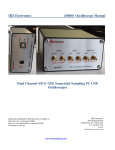
1
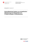
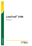
LineTroll R400D User Manual This document describes the Installation-, configuration and use of LineTroll R400D Fault Passage Indicator Information in this document is subject to change without notice. No parts of this documentation may be reproduced in any form by any means without the written permission of Nortroll AS. Copyright 2013 Nortroll AS. All rights reserved. All Nortroll products are trademarks or registered trademarks of Nortroll AS. Other product names are trademarks or registered trademarks of their respective holders. 2013 NORTROLL AS P.O.Box 133 7601 Levanger Norway Contents CONTENTS 3 1. LINETOLL R400D OVERVIEW 5 2. FUNCTIONAL DESCRIPTION. 6 2.1 ADAPTIVE DETECTOR 2.2 LOAD CURRENT COMPENSATION 2.3 OPERATION 2.4 INDICATION 2.5 RESET 7 8 8 9 11 3. WHERE TO MOUNT THE INDICATOR 12 3.1 SUITABLE NETWORKS 3.2 MOUNTING RESTRICTIONS 12 12 4. FAULT DETECTION 13 4.1 LINE SWITCHING – INRUSH BLOCKING 4.2 FAULTS 4.3 AUTOMATIC RECLOSING 4.4 FUSED LINES 4.5 MULTIPLE FAULTS 4.6 CAPACITIVE DISCHARGES 4.7 SETTING THE TRIP LEVEL 4.8 SENSITIVITY 13 14 15 15 16 16 17 17 5. EVENT LOG 19 6. FUNCTIONAL DESCRIPTION GSM MODEM 20 INSERTING THE SIM CARD MANUAL ACTIVATION SMS RECIPIENTS MESSAGE FORMAT MESSAGE FILTERING POLLING INTERVAL HEARTBEAT INTERVAL OTHER GSM FEATURES GPS 20 20 20 21 22 23 23 23 24 7. PROGRAMMING AND SETUP 25 The most important setting to notice: 25 8. MAINTENANCE 26 Battery monitoring 26 9. LINETROLL R400D VERSIONS 27 9.1 Relay output option 9.2 GPRS / DNP3 Modem option 27 27 10. TECHNICAL SPECIFICATIONS 28 11. DIMENSIONS 29 12. MOUNTING INSTRUCTION 30 BEFORE INSTALLATION IN THE FIELD MOUNTING RESET TEST 30 30 30 30 Page 3 User Manual LineTroll R400D MANUAL INSTALLATION REMOTE INSTALLATION VERIFYING THE INSTALLATION 31 31 31 Page 4 User Manual LineTroll R400D 1. LineToll R400D overview The LineTroll R400D is used to locate short-circuit and earth faults in overhead line distribution networks. LineTroll R400D is a 3-phase unit fully covering the different fault configurations that may occur. The indicators are placed at strategic locations along the line such as after branching points and sectionalisers. It mounts on the pole, 3-5 meters below the conductors by means of screws or strap-bands. Live line mounting is done safely, easily and rapidly. Upon detecting a fault on the line, the indicator starts to indicate the fault with a high visibility red strobe flash (permanent faults). This flash can be seen within 2000 meters during night and up to 250m in daylight. It will never be possible to give an accurate distance as it will be very individual. The lens of the indicator can be turned to either side for optimal visibility. The indicator does also have separate indications for transient faults and low battery warning. C.B. Figure 1, Indicators in a fault situation When detecting a fault, all indicators installed between the feeding substation and the fault will operate. The indicators placed behind the fault remain idle. LineTroll R400D has a built in GSM module which will wake up upon a fault and immediately send the alarm to the control center by SMS. The operator will therefore easily identify the faulty section of the feeder, either from Nortroll’s microSCADA system called NetTroll or from the main SCADA system. NorTroll also offers system solutions for forwarding alarms to multiple recipients where the operation central is not staffed 24/7. Page 5 User Manual LineTroll R400D 2. Functional Description. LineTroll R400D’s fault sensing is based on detection changes in the electromagnetic field below the conductors. The unit is fully self-contained, no external transformers or connections of any kind are required. The indicator is looking for a specific sequence in the line conditions to happen before it starts indicating a fault and send the alarm to the control center. The general sequence is as follows: (ref. fig.2) 1. The line should be energised for at least 5 seconds. (Inrush blocking, time is configurable) 2. The line current should increase rapidly above the value set by the user (the nominal trip level). 3. The line should be de-energised. LINE CURRENT I trip I nom t Line Energized INDICATOR Fault Occurs Line Energized 5 sec BLOCKED 15 /30 sec READY RESET / READY INDICATION DETECTION Send Alarm SMS Send Reset SMS t Figure 2. Fault sequence. Page 6 User Manual LineTroll R400D 2.1 Adaptive detector The measured magnetic field (B-field) is applied to an adaptive dB/dt detector. Slow variations in the load current will not affect the detector. A fault current will cause a rapid increase in the B-field which the detector will respond to. The detector will now require that two conditions are satisfied: 1. The relative increase dB exceeds a configurable level. 2. The absolute increase dB T is greater than a pre-set value. (Trip level) NO FAULT I0 = 0 EARTH FAULT I0 ≠ 0 B-field B-field Figure 3, magnetic field It is important to notice that the indicator measure a B-field which is a product of the current flowing in the feeder. The trip-setting values for short-circuit and earth faults will therefore be indicative where the values are based on a horizontal line configuration with 1,5m line-spacing and where the indicator is mounted 3m below the middle conductor. In triangular, vertical or other line configurations, the distances between each phase and the indicator will differ. This means the measured B-field change upon a fault will be different and must be taken into consideration when trip-level is set. Page 7 User Manual LineTroll R400D 2.2 Load Current Compensation Traditional fault passage indicators have sensitivity for PtG-faults that depend on the load current. High load current causes the indicator to be less sensitive for PtG-faults. This problem is overcome with the Load Current Compensation feature (LCC) in LineTroll R400D. With LCC Figure 4, Load current compensation The LCC feature means that the sensitivity for PtG faults will remain unchanged regardless of the load current. This will result in a more accurate detection of sensitive earth faults and LineTroll R400D can detect PtG faults as low as 2A. 2.3 Operation Installation and mounting The indicator must be calibrated to the normal line conditions during the installation of the device. This gives the indicator a “picture” of the B-field below the conductors which will be the basis for detecting changes in the B-field when a fault occurs. This means the indicator must be installed when the line is energized. The indicator continuously monitors the load current in order to adjust to the line conditions at any given time. Inrush blocking time Before any faults can be detected, the line must be energized more than 5 seconds. The inrush restraint algorithm avoids false indication upon energizing of the feeder. (Time is configurable. Page 8 User Manual LineTroll R400D Fault current The fault current has to generate the required increase in the magnetic field as described in section 2.1. Whether the fault should be indicated and what type of fault should be reported will depend on what happens after the reclosing period. The setup of the indicator will also affect how the indicator responds to different fault scenarios. Circuit Breaker (CB) tripping The circuit breaker trip criterion gives the indicator one extra criteria for activation and will give a more accurate detection of a fault. In networks where the feeder is not tripped upon a fault, the CB-trip criteria must be switched off. CB-trip enabled: Line de-energised within 3 to 15 sec after the fault: Line not de-energised within 3 to 15 sec after the fault: Indication No indication CB-trip disabled: Indication not dependent on de-energised line. 2.4 Indication LED indication The LineTroll R400D is equipped with a separate indication board in the bottom lens of the indicator. D1 D2 D3 D4 Figure 5, LED indication card D1: D2: D3: D4: Green; indicates Transient Faults. Red; indicates Permanent faults if lowpower indication mode is selected. Amber; indicates Low Battery. Red strobe flash; indicates Permanent faults if low power indication mode is switched off (Default). The LED’s are also be used to verify correct installation during calibration. See section for installation for details. The lens can be adjusted to allow for maximum visibility. The permanent fault indication (D4) is made as a «strobe» flash with 7 10ms pulses bursting with a 5 sec interval. Figure 6, Strobe flash Low power indication mode for permanent faults The LineTroll R400D has a low power indication mode where the strong strobe flash is switched OFF. Instead a separate red LED is used to indicate permanent faults. This will extend the battery lifetime with approx. two years. Page 9 User Manual LineTroll R400D The visibility of the local flash will be reduced in this mode, but as the indicator will send SMS with the fault alarm anyway, the bright strobe flash is maybe not needed and therefore battery lift-time can be extended instead. Permanent faults A permanent fault is defined as a fault where the line remains de-energized after tripping upon a fault. The time the indicator waits until it defines a fault as permanent can be configured in the range of 40 seconds to 300 seconds. Permanent Fault Last Reclosing Non-successful Fast Auto Reclosing Fault 5 to 15 sec 40 to 300 sec SMS with ’Permanent Fault’ Transient faults A transient fault is defined as a fault where the line is re-energized before the timeout of the permanent fault timer. The line must be energized longer than 15 to 30 seconds. Fault Transient Fault Fast Auto Reclosing 15/30 sec SMS with ’Transient Fault’ Sending SMS alarms The built-in GSM modem is normally switched off to save battery power. The modem will be waked up as soon as the indicator have detected a fault and decided whether the fault is permanent or transient. After having sent the SMS with the alarm message, the GSM modem remains powered for a configurable time to receive eventually messages sent to it. (Default 2min). Time-stamped events The LineTroll R400D is available in a version with GPS and in this version all events sent to the central will be time-stamped with a highly accurate time and date. The time sent will be dependent upon whether the CB-trip criteria are ON or OFF: CB-trip OFF: The time sent in the SMS will be the time when the indicator has validated the fault. The validation time can be set between 3 sec to 15 sec after a fault occurs. Page 10 User Manual LineTroll R400D CB-trip ON: The time sent in the SMS will be the time when the indicator detects that the circuit-breaker has tripped after a fault. 2.5 Reset The indicator can be reset in four different ways: 1. Voltage reset The voltage reset can be switched OFF. When switched ON a delay from the line is energized until the indicator is reset can be set. The following voltage reset delay selections can be made: 5s, 10s, 15s, 20s, 25s or 30s. 2. Automatic timer-reset The timer reset can be set to any value between 1,5h and 12h. 3. Manual reset LineTroll R400D can be reset by turning the lens clockwise to "RESET" position. A magnet is permanently mounted in the lens. A special hot-stick-attachable tool is available for resetting of the indicator from the ground when mounted on a pole. 4. Remote reset The remote reset feature has limited value as the GSM modem is switched off unless the indicator has something to send. The reset command will only be received during a polling sequence, heartbeat message or alarm sending. Page 11 User Manual LineTroll R400D 3. Where to mount the indicator The best economic benefit is obtained when a line survey is executed before mounting fault passage indicators. The indicators should be mounted; Before and after line points with limited access (mountains, forests, private property etc.) to avoid accessing these sections unnecessary. Next to lines branch points (T-offs) to easily locate the faulty T-off. When installing indicators at such points, the use of indicators in every branch is recommended in order to provide complete information in the event of fault. Not doing so may cause confusion since there may be an indication in a branch due to a nonpermanent fault while another branch without indicator may be faulty yet considered healthy. Near line points with sectionalizers to rapidly identify and isolate the fault to facilitate rapid reconnection the healthy sections, for example uing NorTroll’s actuators for sectionalizing switches. 3.1 Suitable networks The LineTroll R400D fault indicator can be used in the following networks: 6 – 132kV distribution networks Radial feeders Isolated neutral networks Directly earthed neutral networks Resistance earthed neutral networks Single and 3-phase network 3.2 Mounting restrictions A pole mounted indicator is only suitable to mount on a pole with no other equipment in the same pole such as underground cables, T-offs, double circuits, sectionalizers, distribution transformers and LV feeders. In case these requirements cannot be obtained, phase-mounted indicators such as LineTroll 110Er must be used in these locations. Adjacent feeders will also affect operation of the LineTroll R400D and the minimum distances are dependent upon the voltage level as shown in the figure below. Page 12 User Manual LineTroll R400D >200kV min. 300 meters 132kV min. 150 meters 66kV min. 100 meters 33kV min. 50 meters 22kVmin 35 meters 11kV min 25 meters Figure 7, mounting restrictions When LineTroll R400D is mounted on fused lines, special percussions should be taken. See section 4.4 for details about fused lines. The indicator should not be mounted on poles near threes or other obstacles. Please contact NorTroll to clear any doubt with regards to mounting location. 4. Fault detection The aim of this section is to describe how the LineTroll R400D indicator behaves in different service situations and network events. 4.1 Line switching – inrush blocking Magnetising inrush current of a line can be very high, the indicator is provided with a 5 to 15 second inrush blocking (the time is configurable) of the dB/dt sensor which prevents it from being activated until the line current is stabilised. Once the blocking time has elapsed, the indicator is enabled for fault detection. LINE I t NO INDICATION t The same inrush blocking will prevent indication in case of switching against a fault. Page 13 User Manual LineTroll R400D 4.2 Faults Permanent Fault Permanent fault Permanent faults will be indicated by strong red strobe flash. The time-out for the indication can be set by the user in the interval 1.5hour to 12 hours. Fault Fast Auto Reclosing Last Reclosing Non-successful D4 5 to 15 sec 40 to 300 sec SMS with ’Permanent Fault’ If the line is restored within the time-out, the LED’s will reset, assuming that the voltage reset is enabled When a second fault occurs while indicating the previous fault If a second fault occurs whilst the LineTroll R400D is indicating a previous permanent fault the indicator will continue to indicate the first fault. The indicator must be reset before it can detect the next fault while indicating a permanent fault. Page 14 User Manual LineTroll R400D Transient (temporary) faults If the fault is cleared by the automatic reclosing cycle and the line returns back to normal service, a single green LED will flash for a configurable time (2 hours – 48 hours). During this period the indicator is ready to detect new faults. If the new fault is a permanent fault, the indicator will start indicating the permanent fault. Transient Fault Fault Fast Auto Reclosing 15/30 sec SMS with ’Transient Fault’ 4.3 Automatic reclosing An automatic reclosing will not activate a non-flashing indicator. If the indicator is indicating a previous fault, the operation due to a reclosing depends on whether the reclosing is successful or not. Non-successful reclosing Closing a breaker onto a fault leads to another trip almost instantly. When the indicator already indicates a fault, it needs to see an energized line for more than a configurable time before it resets the indication. The time can be set from 5 second to 30 seconds). LINE I <30 s t t Successful reclosing The voltage reset feature must be switched ON if the indicator shall reset upon re-energizing of the feeder. The reset time is configurable. (5 to 30 sec) 4.4 Fused lines When the circuit breaker trip criteria are switched ON, a three-phase disconnection of the line is required before the indicator starts indicating the fault. If only one or two of the three phases are disconnected by the fuses due to a fault, the indicator will be reset from the remaining not-disconnected phase and no indication will start. When the circuit breaker trip criteria are switched OFF, the indicator function will depend on another setting; voltage reset. If the voltage reset is ON, the indicator will be reset after 5-30sec and the message sent to the control center will be Transient Fault. The local indication will be with the green LED flashing for a configurable time. If the voltage reset is OFF, the indicator will start a permanent fault indication and will be reset only by the timer, manually or command sent from the control center. The indicator will report the fault as a permanent fault to the control center. Page 15 User Manual LineTroll R400D 4.5 Multiple faults Multiple faults may occur. Defective network components may burn or break due to the electro-dynamic force of the fault current and cause a second fault. Another cause of multiple faults in isolated networks is the rise in voltage in the healthy phases with reference to ground. The voltage may reach up to 1.7 times the nominal voltage. Weak insulators may not withstand such a voltage increase, and a second fault may occur on other location of the feeder. These kinds of faults may be difficult to trace as they often are non-permanent and only appear in situations like the ones mentioned above. 4.6 Capacitive discharges The LineTroll R400D indicator is not directional and detects fault current without discriminating its direction. In case of an earth fault, the capacitive energy of the network discharges in the fault point. It should be verified that the capacitive discharge current downstream the indicator is below the pre-set trip level for PtG faults in order to avoid the indicator incorrectly activating behind the fault. In general, capacitive discharge currents can be neglected in solidly earthed systems unless the total length of the feeder is very long (>50km) and sections of the feeder consists of underground cable. If the total capacitive current exceeds the trip level, it is required to change the trip level or install the indicators in the branching points instead of in the main line. The capacitive discharge of a branching point is limited by its own capacitance, while in the main line the capacitive current of all the branches downstream the indicator is added. Underground cables have larger capacitance than overhead lines. This has to be taken into account when an overhead line feeds an underground cable. L2 L3 PEX-cable L1 Icap= U * LC U * LOH + K T Icap = Capasitive current (A) LOH = L1 + L2 (Total lenght of overhead line in km) LC = L3 (Total lenght of underground cable in km) U = Nominal Voltage (kV) T = 300 for resistor earthed (NCR) and Isolated Neutral T = 900 for solidly grounded neutral K = 10 for oil impregnated cables K = 5 for PEX cables K = 3 for PVC cables Page 16 User Manual LineTroll R400D Calculation example (resistor earthed neutral): LOH = L1+L2= 20km LC = 1km PEX cable U = 22kV 𝐼𝐶𝐴𝑃 = 𝐼𝐶𝐴𝑃 = 𝑈 ∙ 𝐿𝑂𝐻 𝑈 ∙ 𝐿𝐶 + 𝑇 𝐾 22∙20 300 + 22∙1 5 = 5,9 A In order to avoid LineTroll R400D installed downstream of the location in the above example, the trip level for PtG faults must be set to a higher value than 5,9A. The following criteria have to be met: 𝑰𝒄𝒂𝒑 < 𝑰𝒕 ICap = Capacitive current down-streams of the indicator It = Sensitivity for Earth Fault (PtG Trip level) 4.7 Setting the trip level In networks with the feeding transformers neutral isolated from the earth, earth fault current normally is low. In such network it is important to do a thorough analysis of the network to find the correct installation and setting of trip level, especially with regards to capacitive discharge currents. Basic rules for setting the trip level IT is: To avoid incorrect detection because of capacitive current from the network down-stream of the indicator: IC < IT : where IC = capacitive current down-streams of the indicator. To ensure correct detection the following has to be met: IT < IPTG - IC where IPTG = the networks total Earth Fault current. These two rules can be summarised as follows: IC < IT < IPTG - IC 4.8 Sensitivity Earth faults LineTroll R400 monitors the resulting magnetic field below the conductors. The sensitivity for earth faults is a function of the following variables: The trip level set on the indicator (2, 4, 7, 15, 20, 30, 40 or 50 [A]) The line configuration The distance between each phase and the fault indicator The load current at the time of the installation (load current will during fault detection be neglected by the LCC feature). Page 17 User Manual LineTroll R400D The nominal trip setting values listed above are calculated values based on the magnetic field in T (micro Tesla) below a horizontal line configuration with phase spacing of 1,5m and where the indicators are mounted 3 meters below the middle conductor. In other configurations, such as triangular and vertical etc, the distance between each phase and the position of the indicator will differ and the magnetic field sensed by the fault indicator for the same PtG value will in some instances be changed. In networks with relatively high earth-fault currents (>10A) this effect will be less significant. NorTroll offers calculations to be executed on all types of line configurations upon request. Short circuit faults The indicator requires that two conditions are satisfied in order to detect a short circuit fault: 1. The relative increase dB is greater than a certain level (50%, 100% or 200%). 2. The absolute dB T is greater than a pre-set value; 50, 100, 200, 500 or 1000A ref to an indicator located 3 meters below a horizontal line configuration with 1,5m conductor spacing. More narrow spacing will increase these values, making the indicator more sensitive for short circuit faults. The indicator will indicate short circuit faults the same way as for earth faults and the same messages (transient or permanent fault) will be reported back to the central unit. Recommended distances The fault current which is necessary to generate a sufficient increase in magnetic field depends on the; i) Indicators distance (d) from the conductor, -measured from the lowest conductor. ii) Line configuration d Typical distance is 3-4 meters below the conductors Figure. 8 Distance from conductors Page 18 User Manual LineTroll R400D Alignment Correct alignment of the indicator on the pole is important to ensure correct operation. CORRECT LineTroll R400D NOT CORRECT LineTroll R400D Figure 9, Alignment 5. Event log The LineTroll R400D has an event log where all events such as loss of voltage, transient and permanent faults etc. are logged and time-stamped. The LineTroll R400D also does internal checks in the firmware and store results of the checks in the log. The log stores the last 128 events and the log can be downloaded and stored in a memory card and read/presented in a program on a computer. This program is called NetLogger. Please find details about reading the log in the User Manual for NetLogger. The events that can be logged are: Power up reset Temperature (Logged every time the temperature is read) Connection to GSM Network Time set via external radio interface Line is energized (Loss of Voltage Reset) Line is de-energized (Loss of Voltage message) Indicator is reset after a fault by energized line Indicator is reset by timer Permanent fault alarm Transient fault alarm Indicator has detected fault current (Fault Start) Low Battery Alarm Time and position synchronization (GPS) It is possible to set which messages should be logged and which message not logged by configuration parameter as described in the configuration manual. Page 19 User Manual LineTroll R400D 6. Functional description GSM modem The fault indicator and the GSM modem are integrated units which both are controlled by the same controller unit and are powered by the same battery source. In normal operation, when the indicator is ready to detect faults, the GSM modem is switched OFF to save power on the battery and to not influence on the measurement/detection of the magnetically- and electrical field. As soon as the indicator has detected a fault and made it ready to send the correct fault message back to the central (and start local flash indication), the sensor is switched OFF and the telephone modem switched ON. The modem will be awake long enough to send the alarm(s) and to receive messages, commands or configuration settings sent from the central. Inserting the SIM card To find the type of subscription that is most economic and suitable for your system, please contact your local network service provider. We do not recommend using prepaid subscriptions. We also recommend disabling voice communication on the SIM cards and only use SMS services. All PIN codes must be deactivated before installation. Most service providers offer SIM-cards where the PIN codes are deactivated when you receive them. Insert the SIM-card as shown in the picture to the left. The batteries should be disconnected when inserting the SIM card. Remove the top-cap of the indicators housing to access: SIM card socket Programming contact (J3) Activation button (S1) Address settings (SW1) Manual activation The GSM modem can be waked up from sleep-mode by pressing the activation button (S1). The modem will be online for a predefined time, default 5 seconds. SMS recipients The LineTroll R400D sends all its messages as SMS. The LineTroll R400D can be set up to report alarms to up to three different recipient numbers. The messages the unit can send are: Page 20 User Manual LineTroll R400D Message Meaning Transient Fault Sent when the indicator has detected a transient type of fault Permanent Fault Sent when the indicator has detected a permanent type of fault Loss of voltage Sent when the E-field sensor has detected a loss of voltage (No faults) Low battery warning Sent when the remaining battery capacity is less than 20% Boot message Sent when LineTroll is powered up or after a software reset (watchdog reset) Heartbeat message Message sent in configurable interval to verify that the device is working correctly Response/reciept message Sent as a receipt on commands sent to the unit (settings, status check etc.) Each of the above messages can be switched ON/OFF. The Loss of Voltage message is switched OFF by default. However, this message will appear when the indicator has detected a fault and the alarm message shall be sent even if this message is switched OFF. Also when the indicator detects a de-energized line and a status request is received, the response message will contain information about Loss of Voltage. Message format The messages which the Indicator sends follow a defined format. The LineTroll R400D has three different messages which contain different information: Boot message: Fault alarm/status request response: Heartbeat Message 3 3 RSSI 1 0 3 18 Status Date&Time 1 Tx 3 19 Status RSSI 1 Tx RSSI: Signal strength on the GSM network. The value returned is a value between 0 and 31, were 0 equals -113dBm and 31 equals -51dBm. Status: The status field contains a decimal number which is derived from the following bits: Bit0: Transient fault Bit1: Permanent fault Bit2: Loss of Voltage Bit3: Low Battery Date/time: YYMMDDhhmmsstt YY = Year MM = Month DD = Day hh = Hours mm = Minutes ss = Seconds tt = Milliseconds Page 21 User Manual LineTroll R400D Tx: When sending a message from NetTroll, e.g. status request, a Tx number is added in the message. The Tx number send from the indicator in the response is the same number as in the request. Example: If the indicator sends Permanent Fault alarm and Loss of Voltage the STATUS variable will be 0110 = 6. If the status is No Alarms, the STATUS variable will be 0. The Indicator will only respond to a message which starts with a correct password or an appropriate binary protocol heading. Faulty SMS messages i.e. faulty command or message format will be acknowledged with an error message. The implemented codes are as follows: 99 99 99 99 99 1 2 3 4 5 1 1 1 1 1 Unknown command Command not implemented Corrupted command Unable to execute command Command rejected Message filtering The messages in the table above can be sent to one or maximum three recipients. In cases where e.g. the primary recipient should only receive transient and permanent faults and a secondary number receive the other messages, it is possible to filter messages to each of the three recipients. As an example on message filter, the secondary number can be “maintenance central” and should keep track on heartbeat messages, low battery, boot messages etc, whereas the primary (e.g the main SCADA) should receive the real fault messages from the network only. Main NetTroll microSCADA System ComTroll 120 GLR Secondary NetTroll microSCADA System Permanent and Transient alarms LineTroll R400D Heartbeat messages, Low Battery etc ComTroll 120 GLR Figure 10, message filter Page 22 User Manual LineTroll R400D It is advisable to send alarm messages to one recipient (e.g. NetTroll micro SCADA system) and use a separate application to forward alarms to other recipients. NetAlert 3.5 is a program that runs together with NetTroll and will forward alarms to unlimited number of recipients. Polling interval Because the GSM modem is normally switched off, it has a feature providing automatic wakeup in certain intervals called the polling interval. When the LineTroll R400D is due for polling, the GSM modem is powered up and connected to the GSM network to check if a new message is sent to the unit. This can be Status check request Changes for the indicator functionality New settings for trip levels and detection parameters Changes in the GSM settings Request for other information The polling interval can be set between 1 hour and 48 hours. It is advisable to not set shorter polling interval than the default 24 hours in a live installation. Heartbeat interval The indicator sends a heartbeat message to the recipient(s) in a configurable interval. The range is 1 hour to 720hours. Default setting is 144 hours. The heartbeat message contains the current status of the device as well as the GSM signal level. When the receiver system is NetTroll, NetTroll will set up an alarm in the central unit if two consecutive heartbeat messages are missing from the same unit. (Missing Heartbeat Alarm). Other GSM features The LineTroll R400D has several configuration settings for how the GSM modem should operate. Setting alarm/heartbeat up-time Defines the period the GSM modem is connected to the GSM network after having sent an alarm or a heartbeat message. Setting polling up-time Defines the period the GSM modem is connected to the GSM network after having done the regular polling sequence and checked the GSM network for messages addressed to the device. Boot message The boot message is sent when the indicator is powered up or it the internal watchdog function have reset the software. If this message is enabled, it will also be sent when the device is reset when the lens is twisted to RESET position. Sending boot message can be switched OFF. Loss of Voltage message When this message is activated, the unit will send a “Loss of Voltage” message to the recipients. This feature is default switched off. Page 23 User Manual LineTroll R400D Please note the electrical field the indicator see may vary upon several factors such as rain, snow and external influencing sources so it is recommended to keep this feature off to avoid unnecessary messages. When the indicator detects a fault, and the circuit breaker has tripped, the Loss of Voltage bit will be sent anyway to indicate the status of the feeder even if the Loss of voltage message is switched off. When the feeder is restored and the line energized again, the Loss of Voltage bit will also be reset if the line is energized. Response to sender When this function is enabled, the LT-R400D will send a response message back to a sender of a command or configuration setting regardless whether the sender is programmed as one of the three recipient numbers or not. If disabled, the responses will only be sent to the recipient numbers. The messages sent to the device must be in accordance with the correct message format to generate a response. E.g. advertising messages sent from the network provider will not generate any response. Alarm trigger When setting this function to ‘1’, the device will send both the alarm message and the reset message of the same message. Set to ‘0’, the device sends only the active alarms and not when the same alarm is deactivated. Limiting the number of SMS per 24h The number of SMS’ the device can send in a 24 hour period can be set between 10 and 3000. Passwords All messages sent to the device must contain a password corresponding to the programmed password. It is also a separate configuration password which will lock all configuration settings (trip-levels and other important functionality settings) to avoid these being manipulated. It is still possible to request status etc using the main password. GPS The LineTroll R400D is in some versions equipped with a built-in GPS which is used to read the position and to synchronize the on-board real-time clock. The GPS can be activated in a configurable interval (default every 24hour) and will synchronize the time as well as reading the position every time it is switched on. When the device is equipped with GPS, all alarms and status requests will be time-stamped with an accuracy of 100ms. The GPS position can be read from NetTroll FDP configuration utility and will return the position (longitude, latitude) in decimal degrees. Page 24 User Manual LineTroll R400D 7. Programming and setup It is highly recommended to do all the programming/setting before the units are taken to the field for installation on the pole. Normally, most indicators will have the same configuration settings in all the units installed in one network. The exception could be the trip-level which should be verified for each installation site. All configuration properties can be changed remotely from a cell-phone or NetTroll FDP configuration utility at any time, also after installation in the field. Some settings can also be made from NetTroll. A detailed description of the configuration properties is given in the Configuration Manual for the RIS system. This manual covers all possible methods of configuration. The most important setting to notice: Trip level for Earth Faults (PtE) and trip level for Short Circuit Faults (PtP) Relative current increase (Di/Dt in %) Fault duration (in number of periods) for PtG and PtP. Inrush blocking time Voltage reset delay Timer reset CB Trip delay Resetting configuration parameters back to factory values All settings can be reset back to its default values. This must be done in the Collector by pressing the manual activation button in the Collector at the same time as the unit is powered up. Please note that all settings will be set back to default values and the recipient’s number will be deleted. Page 25 User Manual LineTroll R400D 8. Maintenance The LineTroll R400D is maintenance- free under normal running conditions. The heartbeat message sent in configurable intervals will inform the user that the indicator is alive and is working correctly. If the heartbeat message is not sent, the device should be visited for inspection. Battery monitoring The unit is equipped with a battery monitoring feature which keeps track of battery capacity used. When the counter excide a predefined number of mAh, the indicators will send a Low Battery Warning to the recipient number(s) and a yellow LED will start flashing in the indicator. The Low Battery Warning will be sent when approximately 80% of the total capacity is used. The LineTroll R400D can be fitted with different types and number of batteries which will have effect on the total installed battery capacity. The total installed capacity in a device must be set when the device is configured if the installed capacity is different from default values. (See separate configuration manual for details). Changing batteries and resetting battery counters After changing batteries in the Indicator the battery counter must be reset manually. This is done by setting the rotary switch in position ‘1’ before the new batteries are connected. Then connect the batteries and the three status LEDs will flash as a confirmation that the battery counter is reset. Set the rotary switch back to ‘0’ and the indicator starts up again. The LineTroll R400D uses two KBB-20 batteries and one KBB-11. The KBB-20 battery can support high peak currents which occur when the GSM modem is switched on. It is therefore important to not change the two KBB-20 batteries to KBB-11. The KBB-20 has a capacity of 13Ah and KBB-11 16Ah. The theoretical capacity in this configuration is 42Ah, but to adjust for normal deviations due to temperature etc. the total capacity set in the variable Id#37:Battery_capacity should be set to 33000mAh. (See configuration manual for details). Page 26 User Manual LineTroll R400D 9. LineTroll R400D versions The pole mounted fault indicator LineTroll R400D can be supplied in different versions. The standard version has the built-in SMS modem. Other version is listed below. 9.1 Relay output option This version has no GSM modem. Instead alarms can be sent using any third party RTU through a relay interface. The functionality is the same as for all other versions. The relay card has one relay output (NO) for the following messages/alarms: Permanent Fault Transient Fault Loss of voltage Low Battery Warning 9.2 GPRS / DNP3 Modem option The on-board SMS modem is exchanged with a GPRS module with DNP3 protocol for direct connection to SCADA systems. This modem has also SMS messaging where GPRS is made difficult do to network limitations. The fault indicator itself has the same functionalities as described in this document. Details about usage, setup and commissioning is found in separate documentation for the GPRS/DNP3 modem. Page 27 User Manual LineTroll R400D 10. Technical specifications Application: Short circuit and Earth fault indication for overhead lines. System Voltage: MV– voltage network (6-132kV) Grounding system: Isolated, resistor and solidly grounded. Impedance grounded networks with restrictions. Fault-detection: Sensitivity PtG di/dt: 2.5, 4, 7, 15, 20, 30, 40 or 50A (Load current compensated) PtP threshold: PtP di/dt 50,100,200,500 or 1000A 50%, 100% or 200% relative current increase Fault Duration: Configurable: 60ms to 240ms Innrush-blocking: Configurable 5 to 15 seconds Reset: Automatic: Reenergized feeder (Voltage) Delay 5 to 30 seconds 2 to 48 hours Rotating display unit to ”reset” position. From SCADA or NetTroll or FDP-20 hand-held unit from ground Timer: Manual: Remotely: Indication: 1 Green LED for transient faults (Can be switched off) High visibility red strobe-flash for permanent fault Low battery indication LED (amber) Intensity: 40 lumens (permanent fault) Power supply: 3 pcs Lithium D-size primary batteries Battery life time: >1500 hours flashing (8 years of operation). (Low Power Indication Mode will increase the overall lifetime with approx. 2 years. Mounting: 3-5 meters below the conductors Temperature range: -25 to +70 deg Housing: Polycarbonate, UV stabilized Dimension: 100 x 380x200mm Weight: 1300g (including box and 3 pcs battery) Degree of protection: IP55, IK09 & V-0 UL Communication Wireless GSM GPS 2,4GHz short-range radio for configuration/ programming SMS messaging for alarms and remote configuration/programming For positioning data and real-time-clock synchronization. Page 28 User Manual LineTroll R400D 98.78 380.11 11. Dimensions Figure 11, dimensions Page 29 User Manual LineTroll R400D 12. Mounting Instruction Before installation in the field It is recommended to configure all devices using the NetTroll FDP configuration utility before the installation in the field. Alternatively, the FDP-20 hand-held programming unit can be used after the indicator has been mounted on the pole. The FDP-20 can be used to both configure the device and to install it (adjustments of signal levels on the actual position). Mounting The LineTroll R400 is mounted on the pole, typically 3 to 5 meters below the conductors. The indicator can be fastened to the pole with screws or strap-bands. Strap-bands are the easiest method and two strap-bands should be used. 3-5 meter It is also important to align the indicator to the feeder (see figure 9). Please also note the mounting limitations in chapter 3. If the bracket has been mounted on the pole with either screws or cable-ties with the indicator removed from the bracket the indicator housing can be slide down onto the bracket. When the housing is in the correct position a “snap” will lock the housing onto the bracket. RESET The indicator can be RESET by turning the display-unit clock-wise until it stops and then back to normal position. TEST The indicator can be tested by turning the display-unit counter-clockwise until it stops and back to normal position within 9 seconds. The Indicator will then send test-messages to the recipients as follows: Page 30 User Manual LineTroll R400D Transient Fault Low Battery Status OK Permanent Fault Loss of Voltage Status OK The above messages will be sent even if one or more of the messages are disabled. If the message filters are set, the messages will be routed to the recipients according to the filter definition. Manual installation The indicator must be installed on an energized line. After the unit is mounted on the pole the unit has to be adapted to the Electromagnetic field at the installation point and to adjust the internal gain for the sensor inputs. 1. 2. 3. 4. Turn the display unit counter-clockwise ( TEST) until it stops. Leave the display unit in the test position. After the lens has been put into the TEST position, the red, green and yellow LED’s will start flashing. Climb down more than 1 meters below the indicator while the LED’s are flashing After approx. 9 seconds the adaption to the line conditions will start. The LED’s will be OFF during the adaption. After the adaption is finished the LED will show the result of the adaption as follows: GREEN LED RED LED 5. Installation OK E-field too low Place the indicator closer to the line. YELLOW LED Absolute PtP setting too low. Change the absolute trip level for PtP faults to a higher value Twist the lens back to normal position. It is not necessary to reset the indicator after the installation. Remote Installation It is also possible to run the installation process from ground, using the FDP-20 hand-held unit or from NetTroll or any cell-phone by sending SMS. The TEST and RESET options are also available. See the configuration manual for details. Verifying the installation If the installation /adaption to the local conditions on the installation point were successful, the variable Id#38_Last_installation_OK will be set to TRUE in the indicator. If the installation fails, the variable will be set to FALSE. This variable can be read from NetTroll FDP at any time. See the configuration manual for details. Page 31 User Manual LineTroll R400D