1
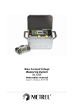
CableTroll 2410 PN: 01-2410- 02/03 User Manual UG CT 2410-RMU February 2010 This document describes the installation and configuration of the RMU Fault Indicator Product no: 01-2410- 02/03 Rev. 0.1 (21.01.09) / TV Draft Rev. 0.2 (05.02.10) / RM Draft Rev. 1.0 (16.02.10) / TV Information in this document is subject to change without notice. No parts of this documentation may be reproduced in any form by any means without the written permission of Nortroll AS. Copyright 2006 Nortroll AS. All rights reserved. All Nortroll products are trademarks or registered trademarks of Nortroll AS. Other product names are trademarks or registered trademarks of their respective holders. 2006 NORTROLL AS P.O.Box 133 7601 Levanger Norway www.nortroll.no Side 2 av 12 0. Contents 0. CONTENTS ......................................................................................................................... 3 1. INTRODUCTION ................................................................................................................. 4 1.1 DEFINITIONS .........................................................................................................................4 1.2 TYPICAL FAULT SITUATION.......................................................................................................4 2. FUNCTIONAL DESCRIPTION ............................................................................................... 5 2.1 OPERATIONAL SEQUENCE – EARTH FAULT (PTG).........................................................................5 2.2 FAULT CURRENTS IN CABLE NETWORK ........................................................................................6 3. USER INTERFACE............................................................................................................... 7 TEST/RESET..............................................................................................................................7 3.1 TEST ...................................................................................................................................8 3.2 RESET ................................................................................................................................8 3.3 LOW BATTERY INDICATION...............................................................................................8 3.4 RESETTING OF BATTERY COUNTER ...................................................................................8 3.5 TEST/RESET FROM SCADA-RTU.........................................................................................8 4. SETTINGS/PROGRAMMING ............................................................................................... 9 5. MOUNTING OF EARTH FAULT SENSOR (EFS).................................................................... 10 6. CONNECTIONS................................................................................................................. 11 7. CALIBRATION................................................................................................................... 11 8. TECHNICAL SPECIFICATIONS ............................................................................................ 12 Side 3 av 12 1. Introduction The CableTroll 2410 RMU Fault Indicator is a fault current indicator for medium voltage cable networks. It detects PtG faults (Earth Fault) A complete indicator consists of split core Earth Fault Sensor (EFS) for mounting on single- and multi – core cables, the main unit with local LED-indication on front panel, output for outdoor indication as well as relay contacts for connection to SCADA-RTU’s. It is designed according to the DIN 43700 / IEC 61554 and fits into the rectangular cut out on the front panel on SF6 insulated Ring Main Units and Compact Switchgear; SafeRing and SafePlus. The unit is SW-controlled with a field upgradeable microcontroller, hence very flexible for customised functionality. The indicator is available in two different versions; low and high range for PtG-fault levels. Each has four fixed levels (user-programmable by micro-switches) in addition to adjustable levels within a certain range. The relay for remote indication has both Normally Open (NO) and Normally Closed (NC) contacts and are available for connection to a SCADA-RTU. 1.1 Definitions As the terminology may this document: EFS: PtE or PtG: RMU: differ from country to country we will use the following definitions throughout - Earth Fault Sensor, split core surrounding all three phases - Phase-to-Earth or Phase-to-Ground Faults = Earth Faults - Ring Main Units 1.2 Typical Fault Situation In an open ring network or a radial network all indicators between the feeding transformer and the fault will start indicating the passage of the fault current from a PtG. 22kV/220V 22kV/220V SLEEPING INDICATORS FLASHING INDICATORS 132kV/22kV 22kV/220V Figure 1. Fault Passage Indication in open ring network. Side 4 av 12 2. Functional description 2.1 Operational sequence – Earth Fault (PtG) When a fault occurs; exceeding the threshold for PtG, the indicator starts with the flashing red LED on the front panel and the external indication (LED-2), if connected. The relay contact will operate (change status); NO-contact will close and NC-contact opens. The indication and the relay status will continue until it resets automatically due a preset time from the internal timer or by pushing the manual Reset button on the front of the indicator. PtG Relay-contact Diagram 1: Permanent PtG-faults Side 5 av 12 2.2 Fault currents in cable network In networks with directly earthed neutral an earth fault is almost equivalent to a short circuit fault. For networks that do not have a directly earthed neutral, the magnitude of the singular earth fault current is determined by the size of the galvanically interconnected network, the voltage level, type of cable and the neutral equipment. IMPORTANT: As the sensor principle is of the threshold type, correct use of the indicator is subject to calculations of earth fault currents and capacitive discharge currents through the EF-Sensor (seen from the feeder). The capacitive discharge current downstream the location of the indicator must not exceed the trip level setting of the indicator. The capacitive discharge current will vary between the different types of cable, and the cable supplier should be consulted about the data for your specific type in order to make the correct calculations. In compensated networks, earth fault detection may not be possible in certain locations depending on the degree of compensation. CAPACITIVE DISCHARGE CURRENTS The CT-2410 Fault Indicator is not directional, it therefore detects current without discriminating its direction. In case of an earth fault, the network capacitive energy discharges in the fault point. It should be checked that the capacitive discharge current downstream of the indicator is below the preset trip level in order to avoid the indicator erroneously activating upon earth faults. If the total capacitive current exceeds the trip level, it is advisable to change the trip level or install the indicators in the branching points instead of in the main line. The capacitive discharge of a branching point is limited by its own capacitance, while in the main line the capacitive current of all the branches downstream of the indicator are added. Underground cables have larger capacitance than overhead lines. This has to be taken into account when an overhead line feeds an underground cable and vice versa. The following simplified formula may be used to estimate the capacitive discharge current of a line and or cable: IC = Capacitive current in [A] U = Nominal voltage in [kV] La = Overhead line length in [km] Lc = Cable length in [km] K = 10; for oil impregnated cables 5; for PEX cables 3; for PVC cables I Basic rules for setting the trip level T is: 1. To avoid incorrect detection because of capacitive current from the network down-stream of the indicator: IC < IT : where IC = capacitive current down-streams of the indicator. 2. To ensure correct detection the following has to be met: IT < IPTG - IC where IPTG = the networks total Earth Fault current. These two rules can be summarised as follows: IC < IT < IPTG - IC Side 6 av 12 3. User Interface Front panel with LED’s for indication and Test/reset button: FAULT LED (Red) TEST/RESET “Low Battery” warning: Yellow LED <20% of capacity left Space for lable to indicate settings or location TEST/RESET This is a multifunction pushbutton, depending on the status of the indicator and the duration that the button is pressed: Duration of pressing 0,6s] [0,6 – 3s] [ 3s Operation Battery status RESET indication TEST Simulate a fault Battery status: Acc.flashing hours (Yellow LED) Flash: Low battery (>1500 h) No flash: OK Fault LED & Ext LED Fault Relay operation Indicate the SW.rev Flash to indicate a fault (until reset) Resets back to normal state Fault state NO-contact closes or NC-contact opens (until reset) Side 7 av 12 3.1 TEST Press TEST/RESET button >3 sec: Red LED starts flashing (=Fault indication) and SCADA-relay operates Until reset by manual push button or timer. close and the Fault LED flash for 1s. 100ms later, the same operation on the Low Battery relay and the Low Battery LED. 3.2 RESET Press TEST/RESET for [0,6 - 3 sec]: The indicator will reset; flashing LED and SCADA-relay returns to normal state. 3.3 LOW BATTERY INDICATION Press TEST/RESET button less than 0,6 sec: The yellow LED will indicate the status of the battery; Flashing: Low battery > 1500 flashing hours exceeded < 20% of total battery capacity left No flashing: Battery OK, accumulated flashing hours < 1500 hours. 3.4 RESETTING OF BATTERY COUNTER When replacing the battery, the battery counter has to be reset. Set SW1[8] in ON position and RESET; press for [0,6 – 3sec] The Yellow LED will illuminate until the SW1[8] is switched back to OFF position, and a RESET executed. 3.5 TEST/RESET FROM SCADA-RTU Terminals 8 and 9, are connected in parallel with the TEST/RESET-button. If these terminals are connected to a poetentialfree signal contact from a SCADA-RTU, all the above operation can be conducted from the SCADA-system by using different closing time; same as the “press-time” for the TEST/RESET-button. Side 8 av 12 4. Settings/Programming The programming switches are accessible behind the front panel. Potmeter (adj.trip.level) Test/Reset button Switch bank Product number: 01-2410 -02 Low range Dip # 1 2 3 4 Trip Level (Fixed) 0 0 1 0 : 50A 1 0 1 0 0 1 1 0 : 80A : 110A 1 1 1 0 5 6 0 0 : 140A Timer Reset : 1 Hour Dip # Dip # Dip# 1 0 : 2 Hours 0 1 1 1 7 : 4 Hours : OFF Signal Duration 0 1 : 40ms : 100ms 8 Batt.count Reset 0 1 : Normal operation : Reset Product number 01-2410-03 High range Dip # 1 2 3 4 Trip Level (Fixed) 0 0 1 0 : 90 A 1 0 1 0 0 1 1 0 : 150A : 230A 1 1 1 0 5 6 0 0 : 330A Timer Reset : 1 Hour Dip # Dip # Dip # 1 0 : 2 Hours 0 1 1 1 7 : 4 Hours : OFF Signal Duration 0 1 : 40ms : 100ms 8 Batt.count Reset 0 1 : Normal operation : Reset Dip # PtG trip level 1 2 3 4 Trip Level (Adjustable) 0 0 0 1 : 6 - 50 A 1 0 0 1 0 1 0 1 : 9 – 80 A : 12 - 110 A 1 1 0 1 : 15 – 130 A Adjust the pot. meter (see above and Ch.7 Calibration Reset automatically Fault indication and relay for SCADA-RTU connection Minimum fault duration – Filter for reliable fault detection. The actual delay is a function of the fault current. When Ifault >> Trip.level delay ̴ 40 / 100ms See § 3.4 Resetting of battery counter Dip # PtG trip level 1 2 3 4 Trip Level (Adjustable) 0 0 0 1 : 10 - 85 A 1 0 0 1 0 1 0 1 : 15 - 145 A : 20 - 210 A 1 1 0 1 : 25 - 330 A Adjust the pot. meter (see above and Ch.7 Calibration Reset automatically Fault indication and relay for SCADA-RTU connection Minimum fault duration – Filter for reliable fault detection. The actual delay is a function of the fault current. When Ifault >> Trip.level delay ̴ 40 / 100ms See § 3.4 Resetting of battery counter NOTE: A RESET is necessary after change of switch-settings in order to initialise the new settings. Side 9 av 12 5. Mounting of Earth Fault Sensor (EFS) Multi-core cable: The sensor is mounted on the screened part of the cable, below the strip-back point, according to the mounting instructions. The screen is turned back underneath the flexible core and terminated at the earth point. Single-core cable: An extension iron (see ordering information) will be necessary. The sensor is to be fastened to one of the phase cables, with the flexible core surrounding all three phases. The sensor should be mounted on the screened part of the cable. The screen of all three conductors should be turned back underneath the flexible-core and then terminated to earth Side 10 av 12 6. Connections *) Note: Term # I/O 1 Input Earth Fault Sensor 2 Input Earth Fault Sensor 3 Output Relay Common 4 Output Relay Fault (NO) 5 Output Relay Fault (NC) 6 Output External indication (LED-2: Black wire) 7 Output External Indication (LED-2: Red wire) 8 Input Reset from SCADA-RTU (-) : 9 Input Reset from SCADA- RTU (+): Description Pot free NO *) Reset from SCADA-RTU must be a potential-free closing contact. No voltage must be applied to this input. 7. Calibration For accurate trip level when using the adjustable ranges, a current generator should be used to inject current through the split-core (iron-band) and simulate an earth fault current. 1. Inject a current corresponding to the required trip level. 2. Adjust the pot.meter until indication If the current generator is not capable to provide the required current, several turns will increase the simulated current by a factor of the number of turns. Example: 3 turns of 50A, equals an Earth fault current of 150A. Side 11 av 12 8. Technical specifications Application: Integration in Ring main Units (DIN 43 700 / IEC 61554) Fault detection principle: 50Hz steady state current detection Phase-to-Earth fault: Prod. # 01-2410-02 01-2410-02 01-2410-03 01-2410-03 Verification time: Fixed Variable Fixed Variable Product 50, 80, 110 or 140A 6 - 130A 90, 150, 215 or 290A 10 -330A 40 or 100msec *) (Shorter verification time available on request) *) Minimum verification time, reduces asymptotic towards 40 (or 100) ms when fault current >> trip level. Local/Internal: 2 LED’s: Fault (PtG) indication: Red LED, f= 0,5Hz Low battery Yellow LED f= 1/15Hz (in indication mode f=0,5Hz) External: Output for ext. LED-2 (outdoor indication) Indication: Remote: 1 NO or NC relay for connection to SCADA-RTU Reset: Timer reset: Manual: Remote: 1,2, 4 hours or OFF Push button on front panel Closing contact from SCADA-RTU Power Supply: Battery: Lithium Current consumption: Idle: Indication: 3,6V – 3,8Ah Lifetime battery: Housing: 3uA, 200 uA 300 uA with LED-2 connected > 2000h flashing hours/10 year idle Low batt. warning after 1500 flashing hours DIN 43 700 / IEC 61554 (96x48x86mm) Polycarbonate, UV resistant Protection Degree (IP): Main Unit front panel: Protection Degree (IP): External indicator: IP 54 IP 65 Ordering information: Prod. # 01-2410-02 01-2410-03 2103 2240 07-1057-00 Product CT2410 with CT & lithium battery, Range: (6) 50 -140A CT2410 with CT & lithium battery, Range: (10) 90 -330A Extension iron band for CT, to be used on single core cables LED-2, external indication LED Replacement battery (KBB-15) 3.6V, 3,8Ah Lithium Side 12 av 12