1
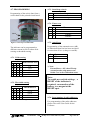
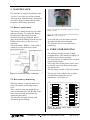
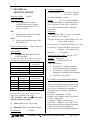
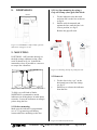
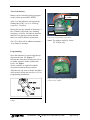
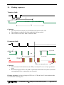
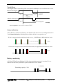
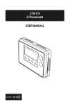
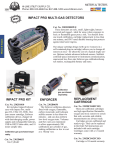
Fault Indicator and Distribution Network Surveillance System USER GUIDE LINETROLL 110Eµ & 110Eµr (PN: 04-1200-00, 04-1200-01 & 04-1200-XX) Phase mounted indicator for overhead line LINETROLL 110E /110Eµr User Guide February 2010 Page 1 of 16 TABLE OF CONTENTS 1. 2. LINETROLL 110E/110EµR OVERVIEW ........................................................... 3 FUNCTIONAL DESCRIPTION............................................................................. 3 2.1. Sensors ......................................................................................................................... 4 2.2. Activation criteria ....................................................................................................... 4 2.3. Indication .................................................................................................................... 4 2.4. Reset criteria ............................................................................................................... 5 2.5. Battery lifetime / maintenance .................................................................................. 5 2.6. Low battery warning .................................................................................................. 5 2.7. Low battery warning reset......................................................................................... 5 2.8. Fault sensitivity ........................................................................................................... 5 3. APPLICATION ..................................................................................................... 6 4. APPLICATION NOTES ........................................................................................ 7 4.1. Energising a healthy line............................................................................................ 7 4.2. Connecting a faulty line while the indicator is activated ........................................ 7 4.3. Transient fault ............................................................................................................ 8 4.4. Fused lines ................................................................................................................... 8 4.5. Multiple faults ............................................................................................................. 8 4.6. Capacitive discharges ................................................................................................. 9 4.7. PROGRAMMING .................................................................................................... 10 4.7.1. Di/dt sensing ........................................................................................................... 10 4.7.2. Threshold sensing ................................................................................................... 10 4.7.3. Start/Stop criteria .................................................................................................... 10 4.7.4. Timer reset .............................................................................................................. 10 4.7.5. Auto-Reset .............................................................................................................. 10 4.7.6. Programming of radio addresses ............................................................................. 10 5. MAINTENANCE ................................................................................................. 11 5.1. Battery replacement ................................................................................................. 11 5.2. Reset battery monitoring ......................................................................................... 11 6. INDICATOR HOUSING ...................................................................................... 11 7. TECHNICAL SPECIFICATIONS ....................................................................... 12 8. DIMENSIONS .................................................................................................... 13 9. MOUNTING. ....................................................................................................... 13 10. FLASHING SEQUENCES: ................................................................................ 15 Terms: Energised line: Voltage or current present De-energised line: Voltage or current not present LT: LineTroll Ordering info: Prod.no.: 04-1200-00: 04-1200-01: Product: LT-110Eµ - new line clamp LT-110Eµr (with radio & new line-clamp) LINETROLL 110E /110Eµr User Guide February 2010 Page 2 of 16 1. LINETROLL 110E/110Eµr OVERVIEW LINETROLL 110E (110E) is a line mounted fault indicator for local indication. LINETROLL 110Er (110Er) has the same functionality as the 110Eu but has an integrated radio that communicate with a pole-mounted device named Collector (CmT-110C, -115C or others) that can be interfaced to a SCADA-RTU or a communication device by means of dry relay contacts or serial-port for remote indication of faults. Unless especially mentioned, all the following information is valid for both 110Eµ and 110Eµr. It is a single phase unit, but as they normally are used in groups of 3, to fully cover different fault configurations that may occur, they are delivered as kit of 3 units each package. It is a Fault Passage Indicator; detects down-streams fault in OH-distribution network; short circuit and earth fault if the network provide sufficient earth fault current. The indicators are placed at strategic locations along the line such as after branching points and sectionalisers. It mounts directly on the high voltage conductor. Live line mounting is easily and rapidly done with a grip-all clamp Hot-Stick. Upon fault sensing, all indicators installed in the faulty phase(s) between the feeding substation and the fault will operate. The indicators placed behind the fault or in the non-damaged phase(s) remain idle. Upon detecting a fault on the line, the indication by means of an intermittent LED- flash (3 red LED’s and 1 amber LED indication for permanent fault and one Green LED for a transient faults). This LED-flash can be seen within 100-200 metres distance. The lens of the indicator allows for uniform 360 degrees monitoring. LINETROLL 110Er provides fast fault location enabling reduction in outage times. This represents enhanced service to the customers thereby improving the utilities image. Another important aspect of using fault indicators is that unnecessary operations of circuit breakers and sectionalisers to locate the fault are avoided. This way the indicators help reduce wear and tear as reclosing cycle causes stress to the switchgear. 2. FUNCTIONAL DESCRIPTION LINETROLL 110E continuously monitors the line voltage and phase current, the sources of information it needs to operate. The unit is fully self contained, no external transformers or connections are required. During normal line conditions; the 110E does not flash. The indicator is looking for a specific sequence of line conditions to happen before it starts indicating locally and remotely. The general sequence is as follows: A. The line should be energised (voltage or current present) for at least 5 seconds. B. The line current should increase instantaneously by the amount of a user set value (the step level), or exceed a threshold value. C. The line should be de-energised. voltage or current not present (optional) LINETROLL 110E /110Eµr User Guide February 2010 Page 3 of 16 However, the user might program the criteria for operation to suit his local requirement by manipulating a bank of micro-switches inside the indicator. Note: Voltage or current as start and stop criteria are user programmable. 2.1. Sensors The magnetic field generated by the line current induces a signal in the indicator pickup coil. The induced signal is applied to a di/dt sensor in order to discriminate between fault current and load current. The di/dt sensor detects instant current increases as is the case when faults occur. The trip level of the di/dt can be set to 6, 12, 25, 60, or 120 A by means of a switch bank inside the unit. A normal variation of the load current will not activate LINETROLL 110E. The line voltage is detected by means of an aerial placed inside the indicator. 2.2. Activation criteria LINETROLL 110E can be easily set to operate in the wanted mode by altering a number of switches inside the unit. In order to avoid activating the indicator due to the magnetising inrush current of the line, it's di/dt sensor is blocked for 5 sec. upon re-energising of the line. While the blocking time elapses, the line current stabilises and does not cause triggering of the di/dt sensor. A fault duration exceeding 60ms is required to activate the indicator. In addition to its di/dt sensor, LINETROLL 110E incorporates a common threshold sensor with threshold levels of 250, 500A, 750A or 1000A. The threshold criterion, if enabled, activates the indicator if the fault current exceeds the selected level. (The inrush blocking is still active in this mode) A rapid line current increase followed by a de-energising of the line within 5 sec. will activate the indicator. It can also be set to indicate upon a rapid current increase without looking for a deenergised line. 2.3. Indication Figure 1: Magnetic field sensor principle. The main indication; 4 red/amber LED’s indicates permanent faults. The secondary indication is a single green LED. Transient fault: Only the green LED flashes for 24h. Permanent fault: Both green and red *) until reset (timer-, auto- or manual-reset). *) Note: to verify a permanent fault, the red Indication is delayed 70 sec. See more detailed info Ch 10 Flashing sequence. Figure 2: Electric field sensor principle LINETROLL 110E /110Eµr User Guide February 2010 Page 4 of 16 2.4. Reset criteria The indicator automatically resets in two different ways: 1) When the line is energised. The voltage or current sensor detects that the line is energised and can in turn reset the indicator after 30 seconds of continuously energised line 2) Automatic reset by internal timer. This timer can be set to: 2, 6, 12 or 24 hours The indicator can also be reset manually at any time by use of a magnet, or by use of the mounting and testing tool KBN-3. Figure 4: Remaining battery capacity as a function of years and temperature 2.6. Low battery warning 2.5. Battery lifetime / maintenance A 3,6V 16,5 Ah Lithium battery powers the indicator. When idle, the 110Eµ consumption is a few micro-Amps only, giving some 9-10 years battery lifetime in normal service. The 110Eµr approx. 5 years due to the additional power consumption for the radio. When the unit is activated, approximately 4 mA are consumed, giving more than 1500 hours of flashing capacity. The battery is fitted with a connector for simple replacement. During the last few months of the battery’s life, an amber LED with a low flashing frequency will indicate that less than 20% of capacity remains and that there is a need for battery replacement. The 110Eµr will in addition send a message “Low battery” to the Collector. 2.7. Low battery warning reset In the case of battery replacement the battery capacity monitoring must be reset. See Ch 5.2. 2.8. Fault sensitivity The indicator’s di/dt sensitivity is limited by the load current. See table in Ch. 7. TECHNICAL SPECIFICATIONS. Figure 3: Initial battery capacity. The indicator detects short-circuit- as well as earth-faults provided the di/dt current change exceeds the detection level or absolute threshold level dependent on programming. LINETROLL 110E /110Eµr User Guide February 2010 Page 5 of 16 3. APPLICATION The application of LINETROLL 110Eµ usually requires a previous line survey so that the best use of it may be obtained. For the best economic benefit it is recommended that the indicators are used: In easily accessibly line points for easy monitoring of the indicator in case of fault, for instance near the road. It is advisable to take binoculars. Before and after line points difficult to reach (mountains, woods, etc.) to quickly locate the fault. Next to line branching points, to easily locate the damaged branch. When installing indicators at such points, the use of indicators in every branch is recommended in order to provide complete information in the event of fault. Not doing so may cause confusion since there may be an indication in a branch due to a nonpermanent fault while another branch without indicator may be faulty yet considered healthy. Compensated and impedance-earthedneutral networks. If indication of earthfaults are required, the indicators sensitivity and the networks residual fault current has to be taken into account. On conductors of 5-36 mm diameter. with special emphasis on: Areas with unpredictable electromagnetic fields caused for example by parallel lines, as a better suited complement to the three-phase fault indicator LINETROLL 111K. Do not use LINETROLL 110Er on: Ring lines or multiple fed lines. Near line points with sectionalisers to rapidly pinpoint and isolate the fault to facilitate rapid reconnection the healthy sections. LINETROLL-110Er is suitable in: 6-69kV Distribution networks including SWER-lines. Radial lines. Multiple circuit lines (Current reset must be used) Solidly-earthed-neutral networks. LINETROLL 110E /110Eµr User Guide February 2010 Page 6 of 16 4. APPLICATION NOTES The aim of this section is to describe how the LINETROLL 110E indicator behaves in different service situations and network events. 4.1. Energising a healthy line As the magnetising inrush current of a line can be very high, the indicator is provided with a 5 seconds blocking which prevents it from being activated until the line current is stabilised. Once the blocking time has elapsed, the indicator is enabled for fault detection. See Figure 5. . Figure 6: Delayed reset of flashing. 4.2. Connecting a faulty line while the indicator is activated Closing a breaker onto a fault leads to another trip almost instantly. As the activated indicator needs 30 seconds with the line energised in order to reset, it will continue indicating. See Figure 7. Figure 7: Reclosing upon a faulted line. Figure 5: Criterion of the blocking time. a) shows the sequence when a fault occurs less than 5 sec after line has been energised: No Indication. If, upon re-energising of the line, the unit is indicating due to a previous fault, the unit will reset if the voltage- or current reset option is enabled, but even in this case the indicator will flash for 30 seconds (depending on the programming, see 4.7) before finally extinguishing. See Figure 6. LINETROLL 110E /110Eµr User Guide February 2010 Page 7 of 16 4.3. Transient fault Transient fault cleared within the last automatic reclosing, will be detected by the green LED. The LED will flash for 24 hours as extended transient indication. Line <5s I Green LED Indication 24h Extended transient fault indication If a new fault occurs within timeout (24h), the indicator will reset the green LED and indicate for the new fault. 4.5. Multiple faults Multiple faults sometimes occur. Defective network components may burn or break due to the electro-dynamic force of the fault current and cause a second fault. Another cause of multiple faults is the increase in the phase to ground voltage on the healthy phases due to the initial earth fault. The phase to ground voltage may reach up to 1.7 times the nominal voltage, depending on the total impedance of the earth loop. If there are weak points in the line, they may not withstand such a large voltage increase. This type of fault may be difficult to find as they often are nonpermanent and only appear in situations like the ones mentioned here. Note: In this situation the indicators may show non-consequent indication. 4.4. Fused lines One operation criterion (assuming automatic voltage reset is enabled) is that, after a fault, three-phase disconnection of the line has to be carried out. If, instead of a three-phase trip, a fuse operates in one or two phases, the voltage of the healthy phase(s) may cause no indication or reset of indication. This is true for indicators placed before the fuse as well as after it. When the criterion of automatic voltage reset is enabled, LINETROLL-110Er is not activated unless the fault causes a three-phase trip in the feeding within 5 seconds after the occurrence of the fault. If there is one disconnection within 5 sec, followed by an automatic reclosing causing a fuse-operation, the indication starts, but will reset after 30 sec. If the automatic reset is switched off, the indicator will continue flashing until it is reset manually or after the automatic timer period has elapsed. LINETROLL 110E /110Eµr User Guide February 2010 Page 8 of 16 4.6. Capacitive discharges The LINETROLL-110Er indicator is not directional, it therefore detects current without discriminating its direction. In case of an earth fault, the network capacitive energy discharges in the fault point. It should be checked that the capacitive discharge current downstream the indicator is below preset trip level in order to avoid the indicator erroneously activating upon earth faults. If the total capacitive current exceeds the trip level, it is advisable to change the trip level or install the indicators in the branching points instead of in the main line. The capacitive discharge of a branching point is limited by its own capacitance, while in the main line the capacitive current of all the branches downstream the indicator is added. Underground cables have larger capacitance than overhead lines. This has to be taken into account when an overhead line feeds an underground cable. To estimate the capacitive discharge current at any line point, you have to calculate the contribution from all the overhead lines and underground cables lengths only beyond that point. Figure 8: Capacitive discharge current calculation example The following simplified formula may be used to estimate the capacitive discharge current of a line: Ic = U * La 300 Ic = U = La = Lc = K = + U * Lc K Capacitive current in A Nominal voltage in kV Overhead line length in km Cable length in km 10; for oil impregnated 5; for PEX cables 3; for PVC cables cables In order to avoid that the LINETROLL110Er is activated by an earth fault downstream the indicator, the following criterion has to be met. Ic < It where Ic = capacitive current downstream the indicator. It = Setting of sensitivity (6 – 120A) LINETROLL 110E /110Eµr User Guide February 2010 Page 9 of 16 4.7. PROGRAMMING Programming of the unit is done from a switch-bank on the printed circuit board. 4.7.3. Start/Stop criteria 4 0 1 Start/Stop criteria Current Voltage Table 3: Start/Stop criteria. 4.7.4. Timer reset 5 0 0 1 1 6 0 1 0 1 Timer reset 2 hours 6 hours 12 hours 24 hours Table 4: Timer reset Figure 9: Close-up of switch-banks. The indicator can be programmed to different current levels for either di/dtsensing or threshold sensing. 1 0 0 0 0 0 Di/dt Current level 6A 12 A 25 A 60 A 120 A Table 1: Di/dt setting 4.7.2. Threshold sensing 1 1 1 1 1 Switch # 2 3 8 0 0 1 0 1 1 1 0 1 1 1 1 Programming of the automatic reset (AR) of indication when line has been energised for more than 30 sec (voltage or current). 7 0 1 4.7.1. Di/dt sensing Switch # 2 3 8 0 0 0 0 1 0 1 0 0 1 1 0 1 1 1 4.7.5. Auto-Reset Threshold level 250 A 500 A 750 A 1000 A AR OFF ON *) Table 5: Auto-Reset *) Note: If Auto-Reset = ON, then CB-trip (circuit-breaker trip) must occur within 5 sec before indication starts. Note: To enable new switch-settings, a RESET of the indicator is required; reconnection of the battery or a magnet at the RESET-spot. 4.7.6. Programming of radio addresses Table 2: Threshold setting For programming of the radio addresses please refer to the User Guide for the Collector. LINETROLL 110E /110Eµr User Guide February 2010 Page 10 of 16 5. MAINTENANCE It is advisable to inspect the indicator once a year or 1 year after it was last activated. The inspection should include a functional test with a magnet to show that the flash frequency and intensity is normal. 5.1. Battery replacement The battery is fitted into the top cap of the indicator housing. To replace the battery, first disconnect the battery from the electronics board by pulling the battery plug, then pull the battery from the top cap. Fitting a new battery is the reverse of removing. The spare battery, KBB-11, comes with a connector so the replacement can be carried out on-site. Figure 11b. Location of soldering pads for resetting battery counter. Note! LT-110Eµr has the pads on the back side of the PCB, see fig 19, page 14. 2009 To activate the reset, the battery must be disconnected and connected again. The indicator has now reset the battery monitoring. 6. INDICATOR HOUSING The indicator housing is made of high strength plastics. The material is highly UV stabilised and is flame retarding. The lens material, in addition, has excellent optical characteristics. An O-ring with silicon grease joint is used to provide a good seal between the upper cap and the lens. The line clamp is made of PA (Poly Amid). Figure 10: LineTroll 110Eµ connectors 5.2. Reset battery monitoring The top cap of the indicator has a colourcoded label indicating the year of manufacture. See Figure 11 . When the battery is replaced with a new battery the battery monitoring must be reset. This is done by short-circuiting the two pads on the underside of PCB while at the same time powering the indicator by connecting the battery. The indicator will now confirm with continuous green flashing. Figure 11: Top-cap colour coding versus the year of manufacture LINETROLL 110E /110Eµr User Guide February 2010 Page 11 of 16 7. TECHNICAL SPECIFICATIONS Current consumption: Nominal voltage : Activated (flashing): 4 mA. 6-69 kV Starting criteria : Battery: Line energised for at least 5 seconds followed by a stepped instant current increase of 6, 12, 25, 60 or 120A OR Non-activated: LT-110Eµ: 30-40µA LT-110Eµr: 300 µA 3.6 V 16,5Ah type KBB-11 Recommended battery replacement approx. every 10 years (5 years for LT 110Eµr) or every 1500 operational hours, whichever comes first. Indication: absolute phase current exceeding 250, 500, 750, 1000A AND a three-phase disconnection of the line within 5 sec. 5 High intensity LED’s; 1 green, 3 red/amber and 1 yellow (“Low battery”) Fault-permanent: All 5 LED’s flash every 5 sec. (10 sec after 12 hours) Fault-transient: 1 green LED flash (every 5/10s) Required fault duration: > 60ms (20ms on request) Reset criteria: 1) Intensity: Voltage/Current reset after 30sec. (Can be disabled) The minimum required current for start/reset, depends on the settings of di/dt or threshold! Thr.hold [A] 250 500 750 1000 Min. start/reset current [A] 10 50 50 50 di/dt Max load Min. start/reset [A] current *) current [A] 6 75A 3 12 75A 3 25 300A 16 60 300A 16 120 1000A 50 *) Maximum load current defines the level for saturation where di/dt sensor cannot detect the programmed increase. NB! If I(load) > Max load It may start flashing without any fault! 2) Timer reset 2h, 6h, 12h, or 24h. 3) Manually (KBN-4 reset tool/ magnet) Line diameter: Low battery: Yellow LED flash every 10s to indicate < 20% capacity left > 12 Lumens Ambient & storage temp.: -40º +85oC. Weight: 460 grams. Standards: Conform to IEC 68-2. Tested according to: EN 61000-6-3 Generic standard – Emission industrial environments EN 61000-6-2 Generic standard – Immunity for industrial environments IEEE 495-1986 §4.4.8 LT-110Eµr w/integr.Short Range Radio: The radio transmit a status telegram to the Collector (ComTroll 110C/115C or other) every 10 sec; containing Permanent or transient faults, low battery warning and Heart Beat. Frequency: ISM band, 2.4 GHz Output: 1mW (0dBm), range: up to 20m*) Line Of Sight (LOS). *) Margin = 20dB, with a Receiver sensitivity = -90dBm (=CmT 110C/115C). Longer distance may be achieved by taken special action when mounting and positioning the antenna and the indicators. 5 – 36mm LINETROLL 110E /110Eµr User Guide February 2010 Page 12 of 16 8. DIMENSIONS 9.2 Live-line mounting by using a Grip-All-Clamp (shot-gun) Hot-Stick: 158 mm 1. 2. Fix the indicator to the hot-stick and raise/lift it to the line as shown in fig 14. Pull the stick downwards and against the line, until the line is in correct position, see fig 15. Release the grip-all stick. Figure 12: LINETROLL 110Eµ/110Eµr physical dimensions. All figures in mm. 9. MOUNTING. LINETROLL 110E mounts directly on the high voltage conductor using a Hotstick as shown in fig 14. It should be mounted as close as possible to a traverse to escape line vibrations. Figure 15: Mounting & Grip-All_clamp hot stick 9.3 Removal. Figure 14Hot-stick mounting, - close to the traverse 1. Fix the claw in the “eye” on the horizontal part of the line-clamp, see fig 15. 2. Pull down, to release the indicator from the line. To fully cover all kinds of faults, NORTROLL recommend to mount indicators on all the phases in multi-phase networks. Locate the indicators at strategic points along the line. 9.1 Before mounting. Make sure the indicator is programmed (see 4.7 Programming) and battery connected before mounting on the line. Figure 16: Removal from the line. LINETROLL 110E /110Eµr User Guide February 2010 Page 13 of 16 Test of the battery. Address Setting for radio. Battery can be tested by placing a magnet on the yellow spot marked: RESET. After 2 sec the indicator will respond by flashing the LED’s, see § 10. Flashing sequences -Test/Reset. During the last few months of the battery’s life, an amber LED with a low flashing frequency (1/10 Hz) will indicate that less than 20% of capacity remains and that there is a need for battery replacement. The LT-110Eµr will in addition transmit a “Low-Battery” message. ON=1 OFF=1 1-2-3. . . . . . 8 Figure 18: Programming switch-bank. Note! The address setting is for the LT-110Eµr only. Programming. Open the indicator by unscrewing the topcap from the lens. See Figure 17. Pull out the electronics board just as far as to enable operation of the switch-bank levers. See Figure. Set the switches as required. Push the electronics board back into position. Align the top-cap arrow with the lens label arrow before closing the unit. See § 4.7 for programming instructions. Figure 19. Soldering pads for resetting Battery counter on LT-110Eµr. Figure 17: Opening/ closing the LINETROLL 110Eµ. LINETROLL 110E /110Eµr User Guide February 2010 Page 14 of 16 10. Flashing sequences: Transient fault: 12h 5s GREEN f=1/5 Hz f=1/10 Hz 24h Comments: On transient fault, only the green LED flash until timeout after 24h. The indicator is ready for new fault within this 24 hour period. The red LED’s will NOT flash on transient fault. Permanent fault: GREEN 5s up to 24h 12h f=1/5 Hz RED f=1/10 Hz 70s timer- or automatic reset Comments: The Permanent Fault indication (red LED’s) is delayed 70 sec to verify a permanent fault. Both red and green LED’s will flash on permanent faults until reset (timer, automatic on energizing of line or manual by use reset-tool). Flashing frequency for both red & green LED’s are 1/5 Hz the first 12 hours and thereafter 1/10 Hz of the remaining time. LINETROLL 110E /110Eµr User Guide February 2010 Page 15 of 16 Test & Reset The magnet must be kept at the yellow reset spot for minimum 2 sec to activate test or reset. Manual with magnet 2s 2s RESET Test sequence Manual with magnet 2s 2s Test sequence TEST-sequence: All 5 LED’s rotate 2 f=1/10s times Status indication: After a Reset or connection of battery, the indicator will after a few sec rotating flash, start a 5 min Status Indication, indicating show whether the line is energized or not. IF line is energised and/or sufficient Load current; 1 GREEN and 1 RED flash for 5 min 5 min IF line is de-energised or not sufficient Load current, a single RED LED flash for 5 min 5 min Battery monitoring A Yellow LED will start flashing 1/10 Hz when remaining capacity is less than 20%, to indicate that the battery should be replaced within the next 6 months. f=1/10 Hz Remaining capacity > 20% LINETROLL 110E /110Eµr User Guide February 2010 Page 16 of 16